CYPE Mentor

Update history​​

CYPECAD

When the selected steel code is the CTE DB SE-A (Spain), EAE 2011 (Spain) or Eurocodes 3 and 4 (EU or any of Eurocode adaptations to other countries), the program allows users to choose thermomechanical rolled steel and Histar® rolled steel (ArcelorMittal).

Compared to conventional steels, the elastic limit for these steels has been reduced depending on the nominal thickness of the section, and so, it may be useful to use them with large sections.

Depending on the selected code, the steel types users can choose amongst are:
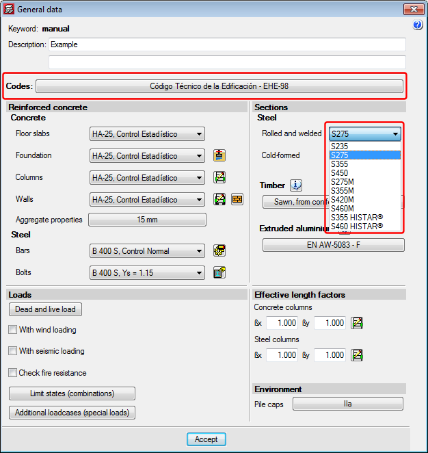
  • CTE DB SE-A (Spain)
    • Conventional rolled steel with elastic limit reduction in accordance with CTE DB SE-A:
      S235, S275, S355 and S450.
    • Thermomechanical rolled steel with elastic limit reduction in accordance with CTE DB SE-A (2015.j version):
      S275M, S355M, S420M and S460M.
    • Histar® rolled steel (ArcelorMittal) (2015.j version):
      S355 HISTAR® and S460 HISTAR®.

  • EAE 2011 (Spain)
    • Conventional rolled steel with elastic limit reduction in accordance with EAE 2011:
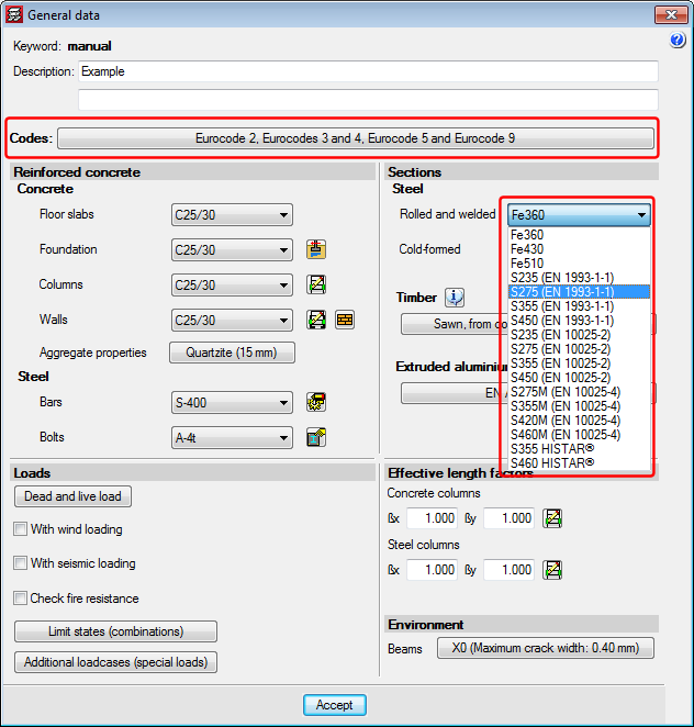
      S235 (EAE), S275 (EAE), S355 (EAE).
    • Conventional rolled steel with elastic limit reduction in accordance with EN 10025-2 (Hot rolled products of structural steels. Part 2: Technical delivery conditions for non-alloy structural steels) (2015.j version):
      S235 (EN 10025-2), S275 (EN 10025-2), S355 (EN 10025-2) and S450 (EN 10025-2).
    • Thermomechanical rolled steel with elastic limit reduction in accordance with EN 10025-4 (Hot rolled products of structural steels. Part 4: Technical delivery conditions for thermomechanical rolled weldable fine grain structural steels) (2015.j version):
      S235 (EN 10025-4), S275 (EN 10025-4), S355 (EN 10025-4) and S450 (EN 10025-4).
    • Histar® rolled steel (ArcelorMittal) (2015.j version):
      S355 HISTAR® and S460 HISTAR®.
  • Eurocodes 3 and 4
    • Conventional rolled steel with elastic limit reduction in accordance with EN 1993-1-1:
      S235 (EN 1993-1-1), S275 (EN 1993-1-1) and S355 (EN 1993-1-1).
    • Conventional rolled steel with elastic limit reduction in accordance with EN 10025-2 (Hot rolled products of structural steels. Part 2: Technical delivery conditions for non-alloy structural steels) (2015.j version):
      S235 (EN 10025-2), S275 (EN 10025-2), S355 (EN 10025-2) and S450 (EN 10025-2).
    • Thermomechanical rolled steel with elastic limit reduction in accordance with EN 10025-4 (Hot rolled products of structural steels. Part 4: Technical delivery conditions for thermomechanical rolled weldable fine grain structural steels) (2015.j version):
      S235 (EN 10025-4), S275 (EN 10025-4), S355 (EN 10025-4) and S450 (EN 10025-4).
    • Histar® rolled steel (ArcelorMittal) (2015.j version):
      S355 HISTAR® and S460 HISTAR®.
    • Rolled steel no longer in use, which are available for compatibility reasons for older jobs:
      Fe360, Fe430 and Fe510.


As of the 2015.i version, when the Colombian NSR-10 concrete code is selected, users can define the type of coarse aggregate in accordance with comments C.8.5.1 of NSR-10, Title C. Users can select the origin of the coarse aggregate:

  • Igneous origin
  • Metamorphic origin
  • Sedimentary origin
  • Unspecified (average national value)

Depending on the origin of the aggregate, the problem will use a different modulus of elasticity in the analysis. The modules of elasticity that are applied, depending on the origin of the aggregate and upon applying the formulas that appear in comments C.8.5.1 of NSR-10 Title C, are:

  • For coarse igneous aggregates:
    Ec = 5500 f 'c in MPa
  • For coarse metamorphic aggregates:
    Ec = 4700 f 'c in MPa
  • For coarse sedimentary aggregates:
    Ec = 3600 f 'c in MPa
  • The average value for all national experimental information, without specifying the type of aggregate:
    Ec = 3900 f 'c in MPa

Some seismic codes specify inertia reduction factors for concrete elements for seismic loads and CYPECAD considers them when these codes are applied.

As of the 2015.h version, users can define inertia reduction factors for concrete elements for seismic loadcases regardless of the code that is used.

To do so, the option “Inertia reduction factors” has been implemented (Job > General options) and only appears when the structure is to be analysed with seismic loading. When this option is selected, a dialogue box opens where users can choose between two options:

  • Based on the code
    The inertia reduction factors for concrete elements for seismic codes considered in the selected seismic code are applied. A list appears displaying the inertia reduction factors (which cannot be modified) for each concrete element (columns, shear walls, concrete walls, masonry walls, beams, floor slabs). If the selected seismic code does not define these factors, a value of 1 is displayed for all the concrete elements.
  • Specified by the user
    Users can introduce an inertia reduction factor for each concrete element in the list (columns, shear walls, concrete walls, masonry walls, beams, floor slabs) which will be taken into account in the seismic loadcases.

As of the 2015.h version, CYPECAD and CYPE 3D allow users to define specific loadcases for temperature and retraction loads. This way, they can be considered in the load combinations in accordance with the selected code.

  • NEC-11 (Ecuador)
    Norma Ecuatoriana de la Construcción. Capítulo 2.- Peligro sísmico y requisitos de diseño.
  • Norma Técnica E.030 (Peru)
    Norma Técnica E.030 Diseño Sismorresistente.

These codes were already implemented in an earlier version of CYPECAD and CYPE 3D. Now, in the 2015.h version, users can define the seismic spectrum.

A design spectrum must be defined for the seismic analysis of the structure. Each seismic code provides the criteria to be followed, within a specific territory, when considering seismic action in the project. Nevertheless, the project designer may adopt, under his/her responsibility, different criteria to that established in the code. The program provides users with the tools to be able to contemplate this possibility for the selected codes. The design seismic spectrum can be:

  • Calculated according to that specified in the seismic code to be applied
  • Specified by users based on their own criteria

More information on which codes allow users to define a customised design spectrum can be found in the Seismic spectrum specified by users section in the CYPECAD page.ermiten esta posibilidad.

The following configuration options have been implemented for post-tensioned drawings (File > Print > Job drawings > Select post-tensioned drawings):

  • Spacing between gridlines
    If the gridline view is activated, their spacing can be specified.
  • Maximum and minimum elevations
    Users can activate view of the maximum and minimum point elevations of the tendon.
  • Inflection point elevations
    It is possible to activate the view of the elevations of the inflection points of the tendon.
  • Symbols table
    A table is included in drawings indicating the meaning of the symbols that have been used in the on-plan drawing of the tendons.
  • Stressing order table
    By activating this option, a table is included in the drawing indicating the references of each stressing order.

As of the 2015.f version, CYPECAD can generate the bill of quantities of the concrete structure that has been analysed taking into account the job items and prices of the Mali construction cost database. To do so, users must install CYPECAD in French and the job must be analysed in accordance with one of the following concrete codes:

  • Eurocode 2 (France)
  • Eurocode 2 (EU)
  • BAEL-91 (R-99) (France)

Using this new implementation, CYPECAD can generate the bill of quantities with the following Price generators:

  • Price generators in French (Algeria, Cameroon, France, Gabon, Ivory Coast, Mali, Morocco, Republic of Congo, Senegal)
  • Price generators in Spanish (Argentina, Chile, Colombia, Mexico, Peru, Spain)
  • Price generators in Portuguese (Angola, Brazil, Cape Verde, Mozambique, Portugal)

For CYPECAD to be able to export the bill of quantities, the user license must be able to connect with the corresponding Price generator.

The following are now indicated in post-tensioned slab drawings:

  • The minimum and maximum points of the path of the tendons, as well as their inflexion points
  • The height of the anchors is included
  • The drawing includes:
    • The distance between the base of the formwork and the bottom part of the duct.
    • The spacing between reference lines is 1 m.
    • The height of the anchors is the height measures from the base of the formwork to the axis of the tendon.

This code was already implemented in previous CYPECAD and CYPE 3D versions. Now, in the 2015.f version the possibility has been added to define a user seismic spectrum.

A design spectrum must be defined to carry out a seismic analysis of the structure. Each earthquake-resistant code provides the criteria that are to be applied within a specific territory when considering seismic action in a project. Nonetheless, users may opt to, under their responsibility, apply other criteria to those established in the code. The program offers, for this seismic code, different ways to proceed, to contemplate both possibilities. The seismic spectrum can be:

  • Calculated in accordance with that specified in the seismic code to be applied.
  • Specified by users based on their own criteria.

This code was already implemented in CYPECAD, CYPE 3D and other CYPE programs as of previous versions. Recently, with the 2015.e version, it became part of the group of codes that can be used to carry out punching shear verifications in accordance with code criteria. 

Now in the 2015.f version, when the NTCRC:2004 code of Mexico is selected in CYPECAD as the concrete code, beams are edited with the advanced beam editor and columns with the advanced column editor. This implies important improvements in the application of these codes:

  • Detailed U.L.S. and S.L.S. check reports for concrete beams and columns (including torsion checks)
  • U.L.S. and S.L.S. reports for steel beams and columns
  • Diagrams and numerical values for necessary and effective steel areas
  • Bar bending diagrams and reinforcement layout configurations in frame drawings
  • Design of variable depth concrete beams
  • And, generally, provides a quick and comfortable graphical interface to edit the resistant elements of the frame (reinforcement bars, lattices etc.)

If a seismic analysis is carried out, the NTCRC:2004 code is compatible with a group of seismic codes, but it is only with the NTC-2004 code that the advanced column and beam editors of CYPECAD can be used and take into the account its criteria for the capacity design in the design of concrete columns and beams.

More information can be found in the section on the “Advanced beam editor” of CYPECAD in the concrete beams webpage. 

The concrete and seismic codes for which CYPECAD takes into account capacity design criteria for concrete columns and beams can be seen in the “Capacity design criteria for seismic design of concrete columns and beams” section of the CYPECAD webpage. 

More information can be found in the section on the “Design codes available for use with the Advanced beam editor” in the webpage dedicated to concrete beams in CYPECAD. 

In the section on “Programs which generate U.L.S. check reports”, more information can be found on the codes that are available for CYPECAD’s advanced column editor. 

The precision of the window in which the elevation difference of the connections is defined, has been increased to 1mm. In previous versions it was limited to 5mm.

The possibility to separately define the reinforcement loss for instantaneous and differed post-tensioned slabs has been added. Therefore, when analysing, two post-tension loadcases will appear: one with instantaneous losses and another with total losses (instantaneous + differed). A new combination will also appear in the combinations in which the initial post-tension loadcase will act with the self-weight of the structure, so the post-tensioning without any loading, one of the most critical steps when tensioning the tendons of the floor slab, can be controlled.