Update history​​

CYPECAD

A transverse section of the beam is represented in the zone of the opening with the reinforcement arrangement, within the edition or introduction dialogue boxes of vertical or horizontal beam openings (edit a beam from the Results tab of CYPECAD using the Advanced beam editor ˃ select the  button of the editor ˃ select any of the edition or introduction options for openings).


CYPECAD allows users to define the Fundamental period of the structure (used to calculate the base shear) in two ways:

  • Based on the code (only way possible in previous versions)
  • Specified by the user (implemented in the 2014.c version)

Either of the two options can be selected in the section Estimation of the fundamental period of the structure within the Code for the calculation of seismic loading dialogue box (General data ˃ Select “with seismic loading” from the “Loads” section ˃ select Mexico as the country and CFE 2008 or NTC 2004).

The value of the fundamental period of a building must be obtained based on the properties of its seismic resistance system, in the direction being considered, in accordance with structural dynamic principles. Alternatively, most seismic codes allow for the fundamental period to be estimated:

  • Using empirical formulas provided within their articles
  • Using other methods, as long as these are adequately sustained analytically or experimentally

The estimated fundamental period is applied in the calculation of the static shear at the base of the structure (base shear) which:

  • Adjusts the dynamic results to minimum values prescribed in the code, if the dynamic method is applied
  • Generate the distribution of the equivalent static lateral forces, if the static method is applied

Article 3.3.5.1 of the CFE 2008 code establishes the calculation of the base shear force by taking the bottom period limit of the plateau of the design spectrum (Ta) as the estimated fundamental period; and article 8.1 of the NTC-2004 code takes any period which coincides with the design spectrum plateau (Ta ≤ T ≤ Tb).

The indicated values are limits established in the codes that can be used in the absence of more precise data. If users have values of the fundamental period which are more adjusted to their structure (calculated using their methods or using software such as CYPECAD, which calculates the fundamental period of the structure in each direction – the values can be consulted after the analysis in the “Justification of seismic action report”: File ˃ Print job reports), they may specify them by selecting the Specified by the user option, located in the Code for the calculation of seismic loading dialogue box, as has been indicated previously.

Normas Argentinas para Construcción Sismorresistente. Parte II: Construcciones de Hormigón Armado.

This code was already implemented in CYPECAD as of the 2013.l version in order to be able to use the Reinforcement ductility criteria and the Capacity design criteria for seismic design which are to be used with the concrete code: CIRSOC 201-2005 (Reglamento Argentino de Estructuras de Hormigón).

Now, for the 2014.c version, the following checks have been included:

  • Compliance with article 2.2.9.2
  • For the capacity check of concrete columns, the design axial force specified in article 2.3.5 is used

Please recall that users do not select the CIRSOC 103-2005 code to be applied. The combination of the CIRSOC 201-2005 concrete code together with seismic code CIRSOC 103-1991 (current seismic code in force in Argentina) or together with seismic code CIRSOC 103-2008 (project seismic code which will substitute CIRSOC 103-1991) implies the reinforcement ductility criteria and capacity design criteria for seismic design of CIRSOC 103-2005 be applied.

  • CFE 2008 (Mexico)
    Manual de Diseño de Obras Civiles. Diseño por Sismo
  • NTC 2004 (Mexico)
    Normas Técnicas Complementarias para Diseño por Sismo

These codes were already implemented in CYPECAD and Metal 3D as of previous versions. Now, in the 2014.c version, CYPECAD offers two options to indicate the value of the Fundamental period of the structure (used to calculate the base shear):

  • In accordance with the code (only way possible in previous versions)
  • User specified (implemented in the 2014.c version)

More information can be found in the section on: “Seismic analysis. Fundamental period of the structure with user values for CFE 2008 and NTC 2004 Mexican design codes” in the new features of CYPECAD of this webpage.

The 2014.b version of CYPECAD and Metal 3D allows for the export of jobs to versions 18 and 19 of Tekla Structures.

A new option Move anchorages, has been implemented in the Post-tensioned dialogue box (Beam Definition tab or Results tab > Post-tensioned > Post-tensioned > Move anchorages) which allows users to move the anchorage in the direction of the tendon (by selecting the anchorage to be moved with the left mouse button) or move the both anchorages and the tendon perpendicularly to it (if any part of the tendon, except its ends, is selected).

The time required to design the concrete columns, especially using the IS 456: 2000 Indian code, has been optimised.

As of the 2014.b version, the horizontal and vertical openings are not eliminated even if the job is analysed or the frame is redesigned. The program rechecks the openings of a frame when they are edited by users.

Information on the improvements that have been carried out upon applying CIRSOC 103-2005 when applying a seismic analysis can be found in the section on Loads on structures. Seismic loads - CIRSOC 103-2005 (Argentina) of this webpage.

Implemented in the previous version (2014.a) was the introduction and check of horizontal openings in beams, for dropped rectangular, “L” or “T” sections (without lattice reinforcement) using the Advanced beam editor of CYPECAD and Continuous beams.

Now, with the 2014.b version, vertical openings (rectangular or circular) can be introduced in flat or dropped rectangular, “L” or “T” beams (without lattice reinforcement).

A new option, New vertical opening, has been implemented to introduce the vertical openings, within the Openings dialogue box (Edit a beam from the Results tab of CYPECAD using the advanced beam editor > select the Openings button button of the editor).

The program allows for vertical openings to be introduced in the flanges and webs of flat and dropped beams, as long as the following conditions are met:

  • The transverse dimension of the vertical opening must be less than one third of the width of the web or less than two thirds of the width of the flange, depending on the zone in which the opening is situated.
  • The length of the opening must be less than the width of the web and the depth of the beam.
  • The position of the vertical opening must guarantee that the cover is respected at all the surfaces of the opening.
  • The free distance between a vertical opening and the support of the beam must be greater than the lateral confinement length of the opening.

Furthermore, the free distance between consecutive openings, be they horizontal or vertical, must be greater than two times the depth of the beam and greater than the width of the web of the beam.

Neither horizontal nor vertical openings may be introduced in the confinement zones established in the selected seismic code.

The resulting section of the beam, having applied the reduction due to the presence of the opening, will be checked using the criteria of the selected code as will, besides the reinforcement of the beam, the reinforcement provided in the opening.

The conditions of the position and dimensions of the openings of the horizontal openings can be consulted in the new features of the 2014.a version.

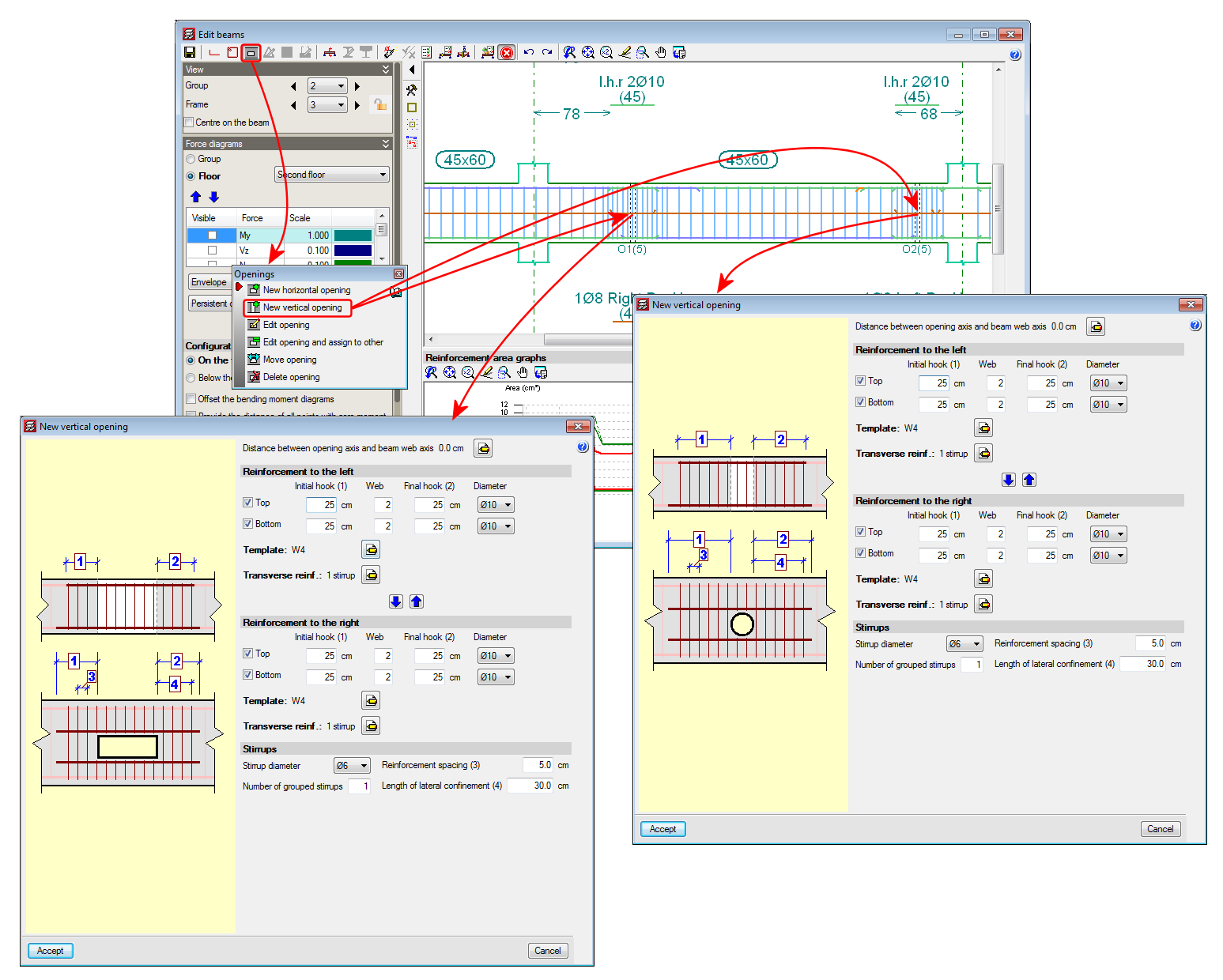
When a vertical opening is introduced and cuts the reinforcement of the frame, the program emits a warning informing users that the arrangement of the reinforcement bars proposed by the program is to be revised, once the opening has been introduced and checked, as there may be a simpler reinforcement arrangement that can be executed on site. Users could even position some of the additional reinforcement bars of the frame in a second layer so the reinforcement arrangement of the opening would be easier to execute.

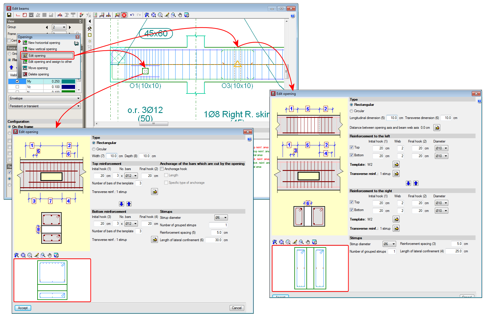
The remaining edition and check options of the Ultimate Limit States (U.L.S.) of the openings, operate in the same manner as for horizontal openings and can be consulted in the Advanced beam editor. Horizontal openings in beams section in the new features of the 2014.a version.

Please bear in mind that neither the horizontal nor vertical openings are considered during the analysis phase, hence their position and dimensions are restricted (as has been indicated previously in their introduction conditions) so the forces that are obtained can be considered valid.

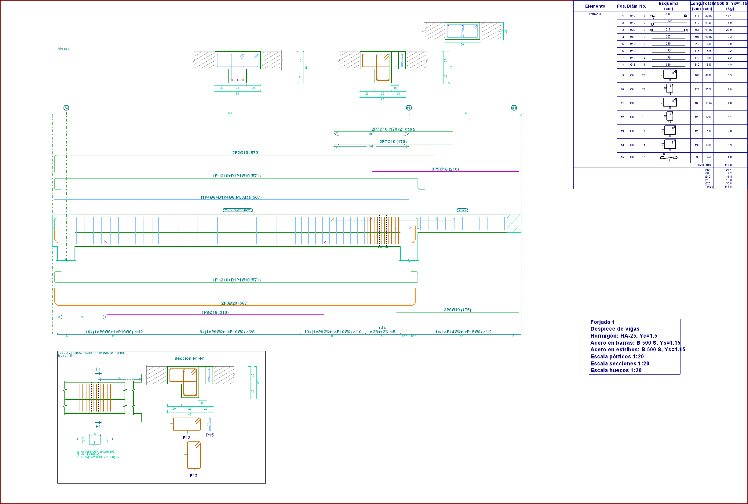
The reinforcement details of the vertical openings are generated automatically within the details of the frame, in the same way as for horizontal openings.

The homogenised values of the properties of the construction elements that are introduced in CYPECAD, to consider their effect in the dynamic analysis of buildings exposed to seismic action, are, as of the 2014.a version: the Thickness of the masonry, Modulus of elasticity X, Modulus of elasticity Y, Shear modulus XY, Poisson’s ratio XY and the Surface load.

All this data is introduced in the Masonry properties – homogenized values – (Beam Definition tab > Loads > Construction elements > Add or Edit option > edit selected type button  or edit type list button  and add ). It is the manufacturers, who due the tests they have carried out on their products, will be able to provide more exact values.

For those cases in which the manufacturers have not provided the required data, a tool has been implemented in the 2014.b version that calculates the homogenised values of the masonry properties based on geometric and resistance data that users can know more easily. This tool is accessed from the previously mentioned dialogue box: Masonry properties – homogenized values, selected using the Property analysis button ().

The properties required by the tool are:

  • Type of construction element
    • Internal partition
    • External wall, visible
    • External wall, to be covered
  • Number of leaves (single or double)
  • Material
  • Type of mortar
  • Type of joint
  • Mortar resistance
  • Standard compressive strength of the unit

In order to define the material, type of mortar, type of joint, mortar resistance and the standard compressive strength of the unit, users must select the adequate option amongst those offered by the program in a drop-down list.

СТРОИТЕЛЬСТВО В СЕЙСМИЧЕСКИХ РАЙОНАХ. Актуализированная редакция

Construction in seismic regions. Updated edition

Implemented in CYPECAD and Metal 3D.