Code implementation and improvements in its application. PS 92 (France); PS 92 (version révisée 2010) (France); RPA 99/v 2003 (Algeria); RPS 2000 (Morocco); RPS 2011 (Morocco)
When analysing with CYPECAD, if users select the French BAEL 91 (R-99) code and combine it with any of the indicated seismic loads, the program will take into account the reinforcement ductility criteria and the capacity design criteria for seismic design of the selected seismic code. These criteria are justified in the detailed Ultimate Limit State reports generated by the Advanced column and beam editors of CYPECAD.
More information on the combined use of the BAEL 91 (R-99) code with the indicated seismic codes can be found in the BAEL 91 (R-99) (France) section.
Règles techniques de conception et de calcul de ouvrages et constructions en béton armé suivant la method des états limites.
This code was implemented in CYPE programs in the 2009.1.a version. In the 2013.b version, a group of codes were included which allowed for the Advanced column editor of CYPECAD to be used (which, besides permitting users to use the advanced column editor, also allowed for the Detailed Ultimate Limit State reports and automatic reinforcement tables to be generated).
Now, in the 2014.aversion, the following improvements have been implemented when using the French BEL 91 (R-99) concrete code:
Detailed U.L.S. and S.L.S. check reports for concrete beams (including torsion checks)
U.L.S. and S.L.S. reports for steel beams
Reinforcement area (required and effective) graphs
Reinforcement bar bending diagrams and reinforcement detailing in the frame drawings
And, in general, allows users to edit the resistant elements of the frame graphically, easily, quickly and comfortably (reinforcement, steel sections, lattices, shear studs, etc.)
By combining the use of the BAEL 91 (R-99) with the following seismic codes, the advanced beamand column editors of CYPECAD can also be used:
PS 92 (France) Règles de Construction Parasismique – Règles PS applicable aux bâtiments – PS 92.
PS 92 (version révisée 2010) (France) Règles de Construction Parasismique – Règles PS applicable aux bâtiments – PS 92 (version révisée 2010).
RPS 2000 (Morocco) Règlement de Construction Parasismique.
RPS 2011 (Morocco) Règlement de Construction Parasismique (version révisée 2011).
Additionally, the U.L.S. reports for columns and beams that are generated by the advanced beamand column editors, include reinforcement ductility criteria and the capacity design criteria for seismic design (bending and shear for the seismic design of concrete supports, and capacity design criteria for shear for the seismic design of concrete beams) indicated in each of the aforementioned codes.
Interaction of the structure with the construction elements (new module)
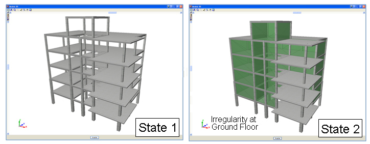
CYPECAD contains a software tool which allows for a dynamic analysis to be carried out on buildings with seismic loads acting upon them, which includes the effects of the non-structural construction elements used in the façades and partitions of the building, and considers various behavioural models of the building corresponding to different situations or states of these elements.
The façades and partitions of the building are considered as being “non-structural” elements, however, during an earthquake, they do provide stiffness to the structure, hence modifying the distribution and magnitude of the forces caused by the seismic action For example, when there is a non-uniform distribution between floors of the stiffness associated with the partitions, the horizontal forces have a greater impact on the columns belonging to the floors with less stiffness, producing shear forces of a high magnitude in the columns. If these have not been designed accordingly, the forces can cause a fragile fracture, endangering the stability of the building, even leading to its collapse.
This is the case of buildings, whose ground floor is destined to be used as retail precincts, and are, generally, irregularly stiff, causing them to be weaker at that floor. The difference in stiffness is due to the height of that floor usually being higher than that of the other floors, and that, due to the use of the floor, is an open floor. Even if the floor below were to have a similar stiffness to that of those above, during the first instants of the earthquake, the partitions of the lower parts of the building fracture, causing an abrupt change in the stiffness, and therefore, an irregularity similar to that described previously. Hence, the stiffness provided by the different non-structural elements can change during the seismic action, due to the cracks and fractures which appear successively.
This module has been developed by CYPE, with the collaboration of the Centro Internacional de Métodos Numéricos en Ingeniería (CIMNE) of the Universidad Politécnica de Cataluña (UPC), financed by the Centro para el Desarrollo Tecnológico Industrial (CDTI) and co-financed by the European Regional Development Fund (ERDF).
There are currently no software tools available on the market for the structural analysis of buildings which integrate the possibility of considering, in a simple manner, the façades and partitions, even though it has been proved that they directly affect the stability, stiffness and safety of the building during an earthquake. Since this CYPECAD module does integrate them, keeping the computation periods within an admissible period, their integration in the building projects will increase their quality and the safety of their occupants, allowing for unfortunate losses, both material and human, to be avoided after an earthquake.
Punching shear and shear checks in footings in accordance with IS 456: 2000 (India)
In previous versions, when users selected the Indian concrete code, IS 456: 2000, the punching shear and shear checks in footings were calculated in accordance with Eurocode 2. As of the 2013.p version, the checks are carried out in accordance with the Indian code, IS 456: 2000 (Indian Standard. Plain and reinforced concrete code of practice – Fourth Revision).
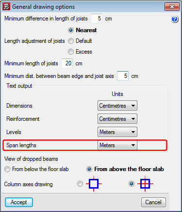
The 2013.o version allows for the measurement units in which the span lengths are expressed in the drawings to be configured. To do so, an option has been implemented: Span lengths in the General drawing options dialogue box (Job > General options > General drawing options).
Now, different measurement units can be selected for Dimensions, Reinforcement, Levels and Span lengths.
Bill of quantities of the structure using the Price generator of Chile
New for the 2013.n version is the possibility for CYPECAD to generate the bill of quantities of a concrete structure if it has been analysed bearing in mind the job units and prices of the Price generator of Chile. To do so, CYPECAD must be installed in Spanish for Argentina or Spanish for Mexico, and the job must have been analysed in accordance with either the Nch 430.Of 2008 (Chile) or ACI 318-99 (Chile) code.
To be able to carry out the export, the user license must include the connection with the corresponding Price generator.
Seismic analysis. Ductility reinforcement criteria and capacity design criteria for seismic design of concrete columns and beams with the NEC-11 (Ecuador) code.
The seismic code of Ecuador, NEC-11 (Norma Ecuatoriana de la Construcción. Capítulo 2.- Peligro sísmico y requisites de diseño) was already implemented in CYPECAD and Metal 3D as of previous versions.
As of the 2013.n version, if users select the NEC – 11 seismic code of Ecuador and combine it with the ACI 318M-08 (USA) concrete code, CYPECAD’s Advanced beam editor and column editor may also be used. Additionally, by using this code combination, CYPECAD applies the ductility reinforcement criteria and capacity design criteria of the NEC-11 code to the seismic design of concrete beams and columns.
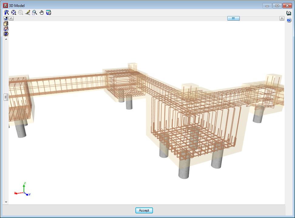
New for the 2013.n version is the option to introduce one and two-pile pile caps with an eccentric column with respect to the axis defined by the piles. Similarly, the program can also analyse pile caps with three or more piles, with a column that lies outside the area defined by the centres of the piles.
Strap beams are required for both cases, to absorb the bending moments that are generated due to the eccentricity of the column. The main reinforcement of the pile cap is designed assuming it is exposed to centred compression loads.
In the case of one and two-pile pile caps, the strap beam is required so to guarantee the equilibrium of the foundation if, as usually occurs, the piles supposedly only resist axial forces.
In all cases, the fact the column is situated outside the area defined by the piles implies the load transmission mechanism from the support to the piles is similar to that of a corbel. The program assumes that the top reinforcement provided in the strap beam is capable of resisting the tensile forces as would the main reinforcement of the corbel, hence the transmission mechanism is guaranteed. This is true as long as the reinforcement of the strap beam has been designed correctly to resist the centring forces and is anchored below the column.
Norma Ecuatoriana de la Construcción. Capítulo 2.- Peligro sísmico y requisitos de diseño.
This seismic load was already implemented in CYPECAD and Metal 3D as of previous versions.
As of the 2013.n version, if users select the NEC – 11 seismic code of Ecuador and combine it with the ACI 318M-08 (USA) concrete code, CYPECAD’s Advanced beam editor and column editor may also be used. Additionally, by using this code combination, CYPECAD applies the ductility reinforcement criteria and capacity design criteria of the NEC-11 code to the seismic design of concrete beams and columns.