It is vitally important to consider the effect non-structural elements (façades and partitions) have on the behaviour of a building exposed to seismic action, especially when open floors are present or a floor contains partitions and façades that are less rigid than those on other floors.
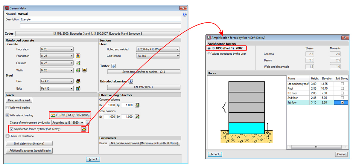
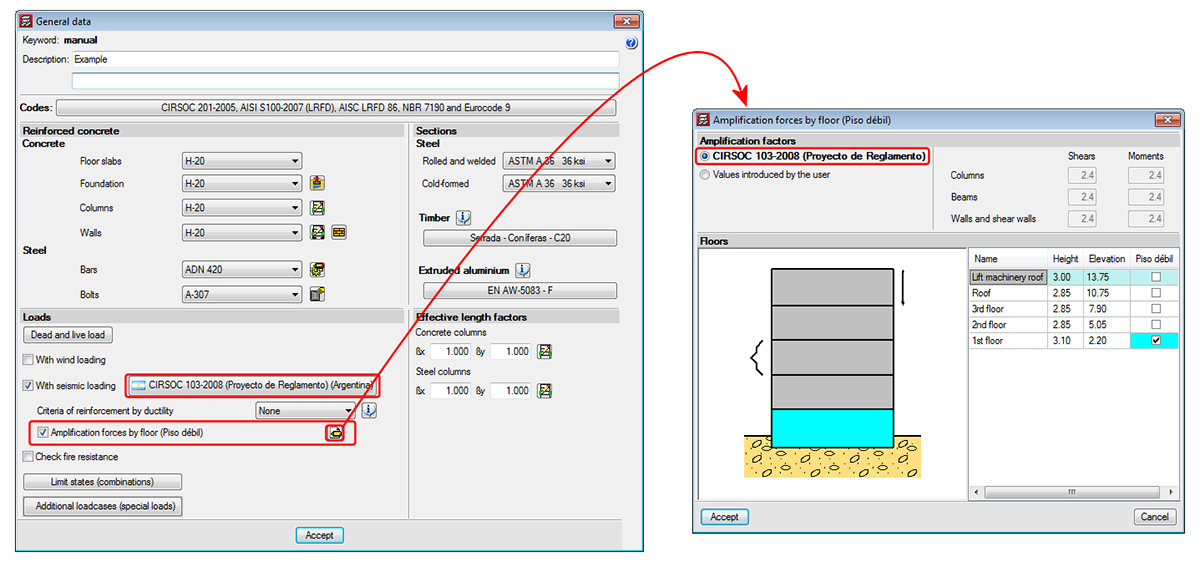
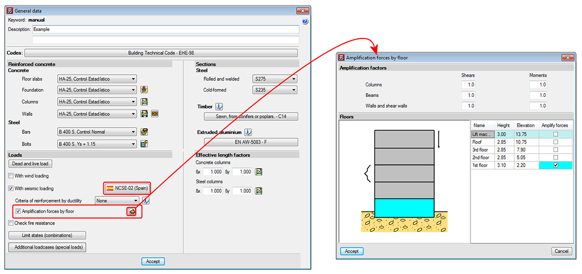
There are design codes that oblige project designers to contemplate the absence or reduction of the stiffness of the partitions and façades on specific floors, by applying moment and shear amplification factors to columns, beams, walls and shear walls situated on floors with less stiffness than the rest when resisting the horizontal displacements caused by seismic action. Examples include IS 13920 (India) -Soft Storey- or Proyecto de Reglamento CIRSOC 103-2008 (Argentina). Logically, the tendency of standards and codes which do not contemplate these effects is to gradually take them into account.
The 2013.l version of CYPECAD allows for moment and shear amplification factors to be applied to columns, beams, walls and shear walls situated on floors chosen by users, regardless of the selected code. To do so, the option Amplification forces by floor has been implemented n the General data dialogue box (Job > General data). Upon activating this option, a dialogue box appears with the same name. If the selected code contemplates the reduced floor stiffness effect due to weaker partitions, the program displays the corresponding moment and shear force amplification factors, which are then applied to the selected floors. Users also have the choice to indicate their own amplification factors. If the selected code does not contemplate these effects, the program allows users to introduce the values they wish for the floors they select.
This method to consider the effect the absence of partitions and façades on specific floors may have when exposed to seismic action, is an approximation to the real behaviour of the building.
In an upcoming version, CYPE will implement a tool that contemplates, in a more precise manner, the influence the distribution of the partitions and façades has on the building. This tool is the result of a R+D+I project CYPE is developing in collaboration with the Centro Internacional de Métodos Numéricos en Ingeniería (CIMNE) of the Universidad Politécnica de Cataluña (UPC), and is financed by the Centro para el Desarrollo Tecnológico Industrial (CDTI) and co-financed by the European Regional Development Fund (ERDF). The aim of this R+D+I project is to develop a dynamic analysis method for buildings exposed to seismic action which includes the effects of the construction elements used in the partitions and façades, and implement them in a design and analysis software tool. This tool is to satisfy the productivity and safety criteria required for the structural project of a building, in other words, ensure the time required to analyse the job is reasonable.