As of the 2013.j version, the export to IFC format (Industry Foundation Classes) now includes the tendons of the post-tensioned slabs that can be introduced in CYPECAD thanks to the new Post-tensioned concrete slabs for buildings module that has also been implemented with this version.
Update history
CYPECAD
Export to IFC
- Published on
- 2013.j
Improvements of drawings with reinforcement detailing only in tables
In the 2013.h version, the option to provide the Reinforcement details only in the table, was implemented. Now, in the 2013.j version, the representation of the text indicating the positions of the bars, has been improved for these types of drawings. The positions are surrounded by an oval frame for both elevation and transverse sections views. Additionally, the labels of the transverse sections have been simplified in accordance with what is customary in the countries that use this type of detailing (American detailing).

- Published on
- 2013.j
Representation of confinement zones
A new option Show confinement zones (located in the View section in the lateral menu of the beam editor) has been implemented. Upon activating this option, the limits of the confinement zones of the transverse reinforcement are represented with blue vertical lines on screen where the reinforcement detailing of the concrete frames is displayed. This option is only visible if an analysis with earthquake loading has been carried out.
- Published on
- 2013.j
Bar anchorage in accordance with user defined options
When introducing hook anchorages using the Advanced beam editor, without specifying the length (Longitudinal reinforcement button
> Edit
select the end of the reinforcement bar), the program takes into account if the option in CYPECAD: The depth minus the cover, with a maximum of, is activated so to calculate the length of the top or bottom anchorage lengths (Job > General data > By position button in Steel in bars
> Beam options > Design/ Code checks > Top reinforcement or Bottom reinforcement button > Anchorage length > The depth minus the cover, with a maximum of).
- Published on
- 2013.j
Maintenance of the floating menu positions
The floating menus that appear using some of the beam editor options are maintained where the user last placed them.
- Published on
- 2013.j
Maintenance of the active option within the editor when another frame is selected
The following options of the beam editor, remain active when the frame being edited is modified (if possible):
U.L.S. and S.L.S. checks at the worst case point
U.L.S. and S.L.S. checks at a point
Consult deflections in spans
These options are only deactivated when the required conditions for their operation are not present (for example: if a U.L.S. check option is active for a frame and the user moves to another whose reinforcement is not defined).
These improvements allow for a quicker check of the frames in the editor, because the number of mouse-clicks are reduces when moving from one frame to another.
- Published on
- 2013.j
Extended and improved error information
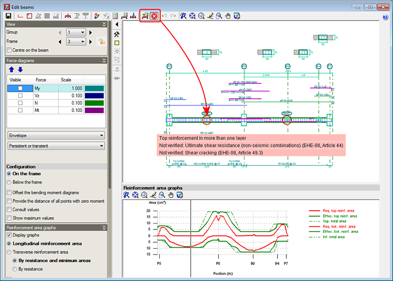
Up until the previous version (2013.i), the Show error messages option (from the Show error messages dialogue that opens when the
button is selected in the top part of the editor) displayed all the error messages due to the introduced reinforcement (zones of the frame without reinforcement, bars with bending shape errors...). As of the 2013.j version, the Show error messages option displays all the errors in the tool-tip that appears when a span containing errors is selected. The information shown is the same as that provided with the “Beam errors” option from the “Beams/Walls” menu of CYPECAD, but with the added list of checks that have been failed, if any are found.
The location points of the errors are visible with all the options of the beam editor, unless users deactivate them (using the “Hide all errors” option in the dialogue box that opens using the
button).
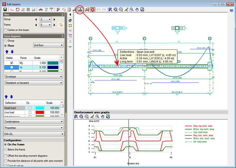
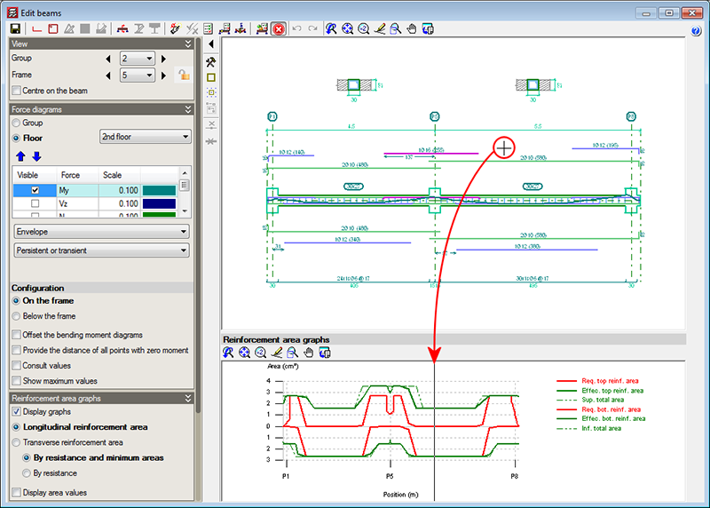
The error information may not be up to date (for example, if the reinforcement of the frame has been modified), in which case, this is indicated in the tool-tip that displays the error information. The errors are not updated automatically after each modification for the same reason as with the deflection calculation, indicated in the previous section. So users can update the error information when they deem adequate (for example, once the reinforcement has been modified several times), the option: Update error information has been implemented, which is represented by the
button (located to the left of the
button).
- Published on
- 2013.j
Consult span deflections
A new option, Consult deflections in spans (represented by the
button in the top part of the beam editor), which displays the deflection values of the selected frame span. This tool provides the same information as is obtained using the “Beam/wall information” option in the “Beams/Walls” menu of CYPECAD.
The Consult deflections in spans option lets users know the deflection of a span without having to leave the beam editor, and takes into account any changes users may have carried out on the frame reinforcement.
The deflection is not calculated each time users change the reinforcement. Users must bear in mind that the deflection calculation process is quite laborious and, if the program were to update the values each time the reinforcement is modified, the reinforcement edition process would be, unnecessarily, very slow. Hence, when the Consult deflections in spans option is used, once changes in the frame reinforcement have been carried out, the program indicates that the span deflections have to be recalculated and asks the user if he/she wishes to continue. If the answer is affirmative, the span deflections will be recalculated and displayed on screen. If the answer is negative, the program will not display the deflection information.
- Published on
- 2013.j
Automatic change of the areas graph depending on the type of reinforcement that is being edited
The reinforcement area representation changes automatically and displays the longitudinal reinforcement area when any of the longitudinal reinforcement edition options are selected (
button in the top part of the editor). Similarly, the transverse reinforcement areas are automatically displayed when any of the transverse reinforcement edition options are used (
button in the top part of the editor).
- Published on
- 2013.j
Position of the cursor in the areas graph
The position of the cursor is represented in the areas graph of the frame by means of a vertical line when the cursor is located in the zone where the reinforcement details of the frame can be viewed, and if any of the following beam editor options have been activated:
- Introduce assembly reinforcement
- Introduce additional reinforcement bars
- Introduce skin reinforcement
- Introduce stitching reinforcement
- Introduce overlaps
- Edit (longitudinal reinforcement)
- Edit shear reinforcement
- Divide shear reinforcement spans
This vertical line moves at the same time as the cursor is displaced over the reinforcement details, and aids in recognising the zone in which the work is being carried out.
This feature is also available when the option “Consult values” (of the represented force graphs) is marked, which is located in the “Configuration” section in the lateral menu of the beam editor.
- Published on
- 2013.j
Capacity design criteria for seismic design of concrete columns and beams with the ACI 318M-08 (USA) code
The 2013.e, 2013.g, 2013.h and 2013.i versions of CYPECAD implemented the capacity design criteria for bending and shear for the seismic design of concrete supports, and capacity design criteria for shear for the seismic design of concrete beams in accordance with the following codes: ACI 318M-08 (USA – International), EHE-08 (Spain), NCSE-02 (Spain) and IS 13920:1993 (India).
Now, implemented for the 2013.j version, are the capacity design criteria for bending and shear for the seismic design of concrete supports, and capacity design criteria for shear for the seismic design of concrete beams in accordance with the NSR – 10 (Colombia) code.
- Published on
- 2013.j
Improved code application. NCh433.Of1996 (Chile)
Norma Chilena Oficial. Diseño Sísmico de Edificios.
This code was already implemented in CYPECAD and Metal 3D, as of previous versions. As of the 2013.j version, if this code is used together with the NCh430.Of2008 concrete code, users can also use CYPECAD’s advanced beam editor.
- Published on
- 2013.j


