The 2013.k version includes the representation of the deviation loads of a tendon in the longitudinal section that appears in its edition dialogue box (Beam Definition tab > Post-tensioned > Edit a tendon).
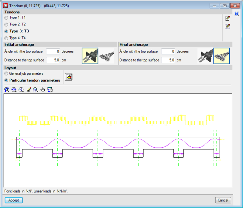


The 2013.k version includes the representation of the deviation loads of a tendon in the longitudinal section that appears in its edition dialogue box (Beam Definition tab > Post-tensioned > Edit a tendon).
The distance between the tendons and the top surface at intermediate supports (their least top cover) is defined as generic data for the job in the Options dialogue box (Beam Definition tab > Post-tensioned > Options), together with the other parameters to be introduced to define the layout of the tendons.
Different parameters can be defined for the tendons when these are being introduced (Beam Definition tab > Post-tensioned > Introduce concentrated tendons or Introduce distributed tendons) or when editing a specific tendon (Beam Definition tab > Post-tensioned > Edit a tendon). Users can select two options in the Layout section of the dialogue boxes that appear when introducing or editing tendons:
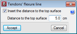
In the new 2013.k version, when a flexure line is introduced, a dialogue box appears in which users can activate the option to Insert the distance to the top surface and define its numerical value for the flexure line that is being introduced. The tendons that cross this flexure line will adopt this value as their minimum top cover at that point. If the option to “Insert the distance to the top surface” has not been activated, the value of the cover will be that which has been defined in the Options dialogue box (Beam Definition tab > Post-tensioned > Options) in the parameter: Distance to the top surface in the intermediate supports.
Bearing in mind the introduction of the flexure lines now includes this possibility, two new options have been implemented in the “Pot-tensioned” dialogue box (Beam Definition tab > Post-tensioned), which allow for a flexure line, which has already been introduced, to be edited (Edit flexure lines of the tendons) or assign a selected flexure line to others that are selected individually or using a capture window (Assign flexure lines of the tendons).
By having the distance between the tendons and the top surface at intermediate supports as an option in the flexure lines box, different top covers can be defined for the same tendon in a more rapid and intuitive manner, which is useful for cantilevers or slabs with varying depths.
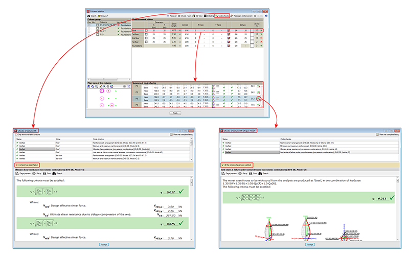
As of previous versions, CYPECAD provided U.L.S. reports for concrete columns using its advanced column editor, which displayed all the checks carried out during the design process (Results > Columns > Edit > select column > select ![]() from the “Summary of code checks” table – to generate the U.L.S. checks report of the selected column span -, or click on the
from the “Summary of code checks” table – to generate the U.L.S. checks report of the selected column span -, or click on the ![]() button – to generate the U.L.S. checks report of the worst case span for each check).
button – to generate the U.L.S. checks report of the worst case span for each check).
To identify the failed checks or consult a specific check, users had to run through the entire report.
Now, as of the 2013.k version, a detailed check and specific check have been implemented in CYPECAD’s advanced column editor, for each U.L.S. check, which helps to speed up the verification procedure. As has been done with the U.L.S. and S.L.S. checks reports for concrete beams, when users select any of the options to consult the U.L.S. checks of the concrete columns ![]() symbol or
symbol or ![]() button), a dialogue box appears, displaying a list of the checks that have been carried out in the top-half of the box. Users select the check to be consulted, which is then displayed in more detail in the bottom-half of the screen.
button), a dialogue box appears, displaying a list of the checks that have been carried out in the top-half of the box. Users select the check to be consulted, which is then displayed in more detail in the bottom-half of the screen.
This dialogue box has the same properties as the dialogue box that appears when using the concrete beam editor, explained in detail, in the previous section of this webpage (Advanced beam editor of CYPECAD).
In previous versions, the U.L.S. and S.L.S checks dialogue box displayed the complete report of the checks carried out by the program ![]() U.L.S. and S.L.S. checks at the worst case point or
U.L.S. and S.L.S. checks at the worst case point or ![]() U.L.S. and S.L.S. checks at a point buttons of the Advanced beam editor). To identify the failed checks or consult a specific check, users had to run through the entire report.
U.L.S. and S.L.S. checks at a point buttons of the Advanced beam editor). To identify the failed checks or consult a specific check, users had to run through the entire report.
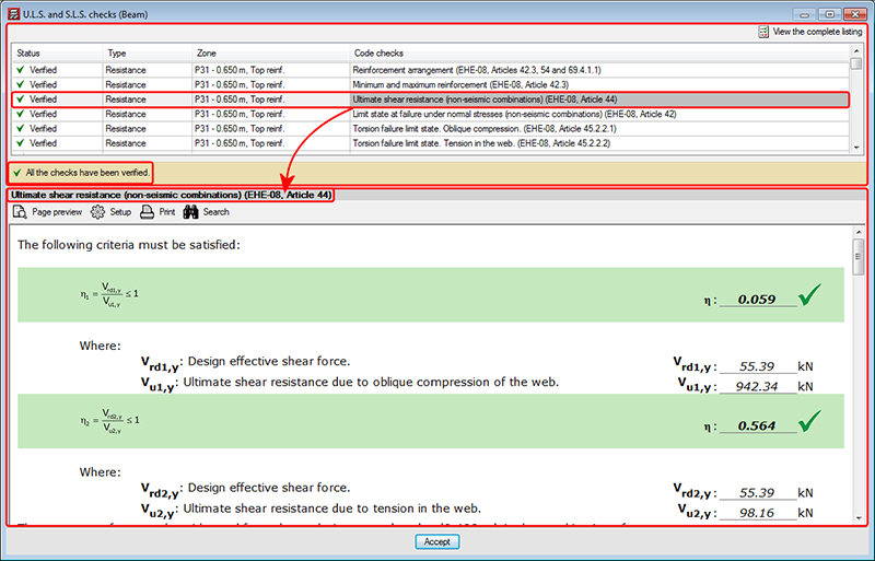
Now, as of the 2013.k version, a detailed check and specific check have been implemented in the dialogue box, for each U.L.S. and S.L.S. check, which helps to speed up the verification procedure. These checks can be found in the U.L.S. and S.L.S. checks dialogue box; within the top-half is a list of the checks that have been carried out (indicating whether or not these fail). Users select the check to be consulted, which is then displayed in more detail in the bottom-half of the screen:
The checks that have been carried out are displayed in a table containing the following columns:
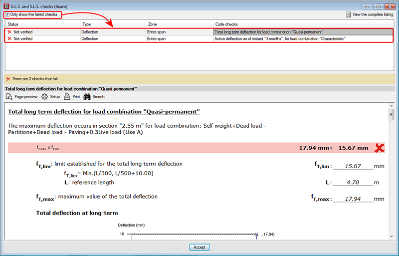
Above the table is a box that users can mark to Only show the failed checks, which will not appear if no checks fail or if all fail.
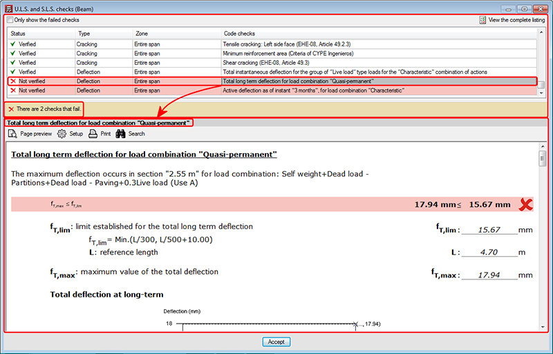
Below the table, the program indicates the number of checks that fail (together with a red cross on the left) or a text indicating “All the checks have been verified” (together with a green mark on the left).
The details of the check selected in the table appear in the bottom-half of the “U.L.S. and S.L.S. checks” dialogue box. This part of the dialogue box is headed with the description of the check selected in the table displaying the checks (the same text that appears in the Code checks column), and is the followed by detailed information on the check. This information can be seen in the preview of the print-out or be printed directly.
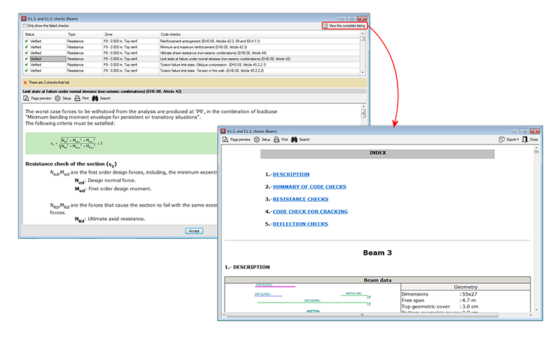
The complete U.L.S. and S.L.S. checks report (![]() U.L.S. and S.L.S. checks at the worst case point or
U.L.S. and S.L.S. checks at the worst case point or ![]() , U.L.S. and S.L.S. checks at a point buttons, both of the selected span) as was in previous versions in the U.L.S. and S.L.S. checks dialogue box, can now be obtained by selecting the
, U.L.S. and S.L.S. checks at a point buttons, both of the selected span) as was in previous versions in the U.L.S. and S.L.S. checks dialogue box, can now be obtained by selecting the ![]() button, situated in the top right-hand corner of this dialogue box.
button, situated in the top right-hand corner of this dialogue box.
These detailed and specific U.L.S. checks have also been implemented in CYPECAD’s advanced column editor, and in the U.L.S. checks dialogue box of Metal 3D or Integrated 3D structures of CYPECAD.
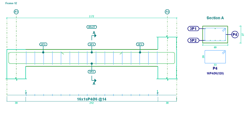
In the 2013.h version, the option to provide the Reinforcement details only in the table, was implemented. Now, in the 2013.j version, the representation of the text indicating the positions of the bars, has been improved for these types of drawings. The positions are surrounded by an oval frame for both elevation and transverse sections views. Additionally, the labels of the transverse sections have been simplified in accordance with what is customary in the countries that use this type of detailing (American detailing).
When introducing hook anchorages using the Advanced beam editor, without specifying the length (Longitudinal reinforcement button ![]() > Edit
> Edit ![]() select the end of the reinforcement bar), the program takes into account if the option in CYPECAD: The depth minus the cover, with a maximum of, is activated so to calculate the length of the top or bottom anchorage lengths (Job > General data > By position button in Steel in bars
select the end of the reinforcement bar), the program takes into account if the option in CYPECAD: The depth minus the cover, with a maximum of, is activated so to calculate the length of the top or bottom anchorage lengths (Job > General data > By position button in Steel in bars ![]() > Beam options > Design/ Code checks > Top reinforcement or Bottom reinforcement button > Anchorage length > The depth minus the cover, with a maximum of).
> Beam options > Design/ Code checks > Top reinforcement or Bottom reinforcement button > Anchorage length > The depth minus the cover, with a maximum of).
The following options of the beam editor, remain active when the frame being edited is modified (if possible):
These options are only deactivated when the required conditions for their operation are not present (for example: if a U.L.S. check option is active for a frame and the user moves to another whose reinforcement is not defined).
These improvements allow for a quicker check of the frames in the editor, because the number of mouse-clicks are reduces when moving from one frame to another.
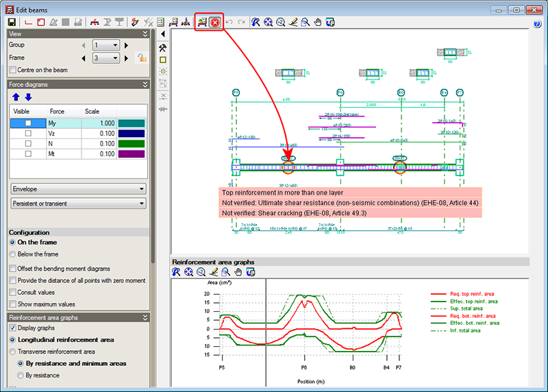
Up until the previous version (2013.i), the Show error messages option (from the Show error messages dialogue that opens when the ![]() button is selected in the top part of the editor) displayed all the error messages due to the introduced reinforcement (zones of the frame without reinforcement, bars with bending shape errors...). As of the 2013.j version, the Show error messages option displays all the errors in the tool-tip that appears when a span containing errors is selected. The information shown is the same as that provided with the “Beam errors” option from the “Beams/Walls” menu of CYPECAD, but with the added list of checks that have been failed, if any are found.
button is selected in the top part of the editor) displayed all the error messages due to the introduced reinforcement (zones of the frame without reinforcement, bars with bending shape errors...). As of the 2013.j version, the Show error messages option displays all the errors in the tool-tip that appears when a span containing errors is selected. The information shown is the same as that provided with the “Beam errors” option from the “Beams/Walls” menu of CYPECAD, but with the added list of checks that have been failed, if any are found.
The location points of the errors are visible with all the options of the beam editor, unless users deactivate them (using the “Hide all errors” option in the dialogue box that opens using the ![]() button).
button).
The error information may not be up to date (for example, if the reinforcement of the frame has been modified), in which case, this is indicated in the tool-tip that displays the error information. The errors are not updated automatically after each modification for the same reason as with the deflection calculation, indicated in the previous section. So users can update the error information when they deem adequate (for example, once the reinforcement has been modified several times), the option: Update error information has been implemented, which is represented by the ![]() button (located to the left of the
button (located to the left of the ![]() button).
button).