Update history​​

CYPECAD

Design codes of diverse countries include capacity design criteria for seismic design of concrete beams and columns. These criteria aim to avoid fragile failure modes which can cause the structure to collapse due to mechanism formation. The capacity design criteria is based on increasing the bending resistance of the supports with respect to that of the beams, and increase the shear resistance of the columns and beams in proportion, improving the ductility of the structure. By applying these criteria, plastic failure is avoided at the supports rather than at the beams and shear (fragile) failure before failure due to bending, is also avoided.

The tendency of the diverse codes, with regards to seismic construction, is to use these criteria by applying bending overresistance factors to the supports with respect to the beams, and shear overresitance factors with respect to the bending resistance for columns and beams.

The 2013.e version of CYPECAD implements the capacity design criteria for bending at the supports in accordance with Annex 10 of the EHE-08 code. The remaining checks of the EHE-08 code and checks of other design codes will be implemented in upcoming program updates.

The 2013.e version incorporates a new beam editor in CYPECAD (Results > Beams/Walls > Edit beams). The same editor is used in Continuous beams, which was implemented in the 2012.m version and has been improved in several updates of the 2013 version. Hence, beam edition in CYPECAD has substantially improved using the features offered by the new editor:

  • Detailed U.L.S. and S.L.S. check reports for concrete beams
  • U.L.S. and S.L.S. reports for steel beams
  • Diagrams of required and effective reinforcement areas
  • Improved edition of the resistant elements of the frames: reinforcement, steel sections, infills, trusses, connectors, etc.

The new beam editor is currently available in CYPECAD for design in accordance with the Spanish EHE-08 concrete design code and Brazilian ABNT NBR 6118:2007 concrete design code. More concrete design codes will be implemented in upcoming program updates.

U.L.S. and S.L.S. reports for concrete beams (with check for failure due to torsion and design criteria for seismic loads)

CYPECAD, using its new beam editor, generates Detailed ultimate and serviceability (U.L.S. and E.L.S.) limit state check reports for concrete beams (Comprobaciones  E.L.U. y E.L.S. en el punto pésimo and Comprobaciones  E.L.U. y E.L.S. en un punto buttons of the editor). In previous versions, the checks on the concrete beams were carried out internally by the program, but these were not indicated in the U.L.S. and E.L.S. reports. Now, the U.L.S. and E.L.S. reports that are generated also indicate the articles of the codes in accordance to which the checks refer to.

More features of the beam editor are present in CYPECAD than in Continuous beams due to the torsional and seismic analysis performed by CYPECAD. The U.L.S. and E.L.S. reports provided in CYPECAD include checks for failure due to torsion in reinforced concrete beams (available for the Spanish EHE-08 and Brazilian ABNT NBR 6118:2007 concrete design codes, as well as all the other checks and the new beam editor) and also incorporates the specific checks of the design criteria for seismic loads for reinforced concrete beams (available when the selected concrete and seismic codes are the Spanish EHE-08 and NCSE 02 codes).

U.L.S. and S.L.S. reports for steel beams

The detailed U.L.S. and S.L.S. check reports for steel beams ( and  buttons of the editor) and the steel beam series check (  button of the editor) are also obtained in the new beam editor (in previous versions, these were obtained using the Beam errors option in the Beams/Walls option in the Results tab).

Diagrams of required and effective reinforcement areas

CYPECAD’s new beam reinforcement editor includes, as does Continuous beams, diagrams indicating the required and effective areas of the reinforcement provided in the edited frame.

Reinforcement bar bending diagrams in frame drawings and column detailing drawings

Bar bending diagrams of the longitudinal and transverse reinforcement of frames are included in the drawings of frames (depending on the selected code) belonging to jobs which can use CYPECAD’s new beam editor.

The bar bending diagrams are also included in the Column detailing drawings.

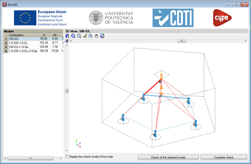
A new tool: Strut3D, has been incorporated in the 2013.e version of CYPECADMetal 3D and Foundation elements. Strut 3D checks foundation pile caps using a general calculation method in which the D regions of the reinforcement are analysed using a strut and tie model, in order to guarantee the structural requirements are met in accordance with the standards. The strut and tie model used has been previously validated by a linear finite element analysis.

Additionally, Strut3D provides a graphical output of the results, allowing users to consult them on screen and in the detailed verification reports, which indicate whether or not they comply with the standards. The information provided is of great importance, as it is this information which will be used by the project designer when deciding on and justifying the design.

Strut3D is the result of a development project developed by CYPE with the collaboration of the 'Instituto de Ciencia y Tecnología del Hormigón' (ICITECH) of the 'Universidad Politécnica de Valencia' (UPV), financed by the 'Centro para el Desarrollo Tecnológico Industrial (CDTI) and co-financed by the European Regional Development Fund (ERDF).

Therefore, Strut3D is a breakthrough compared to other products currently in the market, because it verifies and justifies compliance with the design standards based on an optimised strut and tie model in a simple and intuitive manner for its users.

To access Strut3D in CYPECAD or Metal 3D, users must have a license providing access to version 2013.e or higher in either of these programs, and their Pile caps module. To access Strut3D in the Foundation elements program, users only require the program with version 2013.e or greater.

The first version of Strut3D currently only considers the Spanish EHE-08 concrete design code. More concrete design codes will be implemented in upcoming program updates.

More information on this CYPE program tool will be available shortly.

Norme Tecniche per le Costruzioni (14 gennaio 2008) Paragrafo 3.2 Azione Sismica.

This code was already implemented in CYPECAD and Metal 3D as of previous versions for use with the dynamic analysis method (spectral modal), which it proposes.

A static analysis method (equivalent lateral force) is included in the 2013.e version of CYPECAD. Users can select the analysis method (dynamic or static) using the Analysis method option within the dialogue box in which seismic action is defined.

Normas de seguridad estructural de edificaciones y obras de infraestructura para la República de Guatemala.

This code was already implemented in CYPECAD and Metal 3D as of previous versions for use with the dynamic analysis method (spectral modal).

For this code, the 2013.e version includes in CYPECAD:

  • A static analysis method (equivalent lateral force)
    Users can select the analysis method (dynamic or static) using the Analysis method option within the dialogue box in which seismic action is defined.
  • The correction due to base shear
    This correction is applies when the seismic design is carried out using the dynamic analysis method (spectral modal).

As of the 2013.d version, when the program exports to IFC format (Industry Foundation Classes), the steel sheeting and concrete layer of composite slabs are also exported. These elements are not visible in the 3D view generated by CYPECAD but are exported to IFC format in three of the four available formats (IFC 2x3, Revit IFC 2x3, Allplan IFC 2x3).

Reglamento para el Análisis y Diseño Sísmico de Estructuras.

This code was already implemented as of previous versions for CYPECAD and Metal 3D for the dynamic analysis method (spectral modal).

The 2013.d version includes in CYPECAD:

  • static analysis method (equivalent lateral force)
    The analysis method selection (dynamic or static) is carried out using the Analysis method option within the dialogue box where the seismic load is defined.
  • Correction due to base shear
    This correction is applied to the seismic analysis when this is done using the dynamic analysis (spectral modal). More information on this topic can be found in the Correction due to base shear for seismic design using dynamic analysis method section of the CYPECAD web site.

Reglamento Argentino de Acción del Viento sobre las Construcciones.

Code implemented in CYPECAD.

South African National Standard. The structural use of steel. Part 1: Limit-states design of hot-rolled steelwork.

Code implemented in Metal 3D.

Norma Técnica E.030 (Peru). Static analysis method and correction due to base shear.

Peru’s E.030 code (seismic design) was already implemented in previous versions in CYPECAD and Metal 3D for the dynamic analysis method (spectral modal).

For this code, the 2013.c version includes in CYPECAD:

  • A static analysis method (equivalent lateral force)
    Users can select the analysis method (dynamic or static) using the Analysis method option within the dialogue box in which seismic action is defined.
  • The correction due to base shear
    This correction is applied when the seismic design is carried out using the dynamic analysis method (spectral modal).

Règles NV 65. Règles définissant les effets de la neige et du vent sur les constructions et annexes.

Implemented in CYPECAD. This code was already implemented in the Portal frame generator.

As of the 2013.b version, the export to IFC format (Industry Foundation Classes) includes the forms of joist floor slabs and lattice reinforcement of reinforced joists. These elements are not visible in the 3D view generated by CYPECAD but are exported to IFC in any of the four available formats (IFC 2x3, Archicad IFC 2x3, Revit IFC 2x3, Allplan IFC 2x3).