Update history​

CYPEFIRE Hydraulic Systems

Calculation of the distance between supports and seismic supports

As of the 2018.g version, CYPEFIRE Sprinklers automatically calculates the distances between supports and seismic supports. This calculation is carried out as follows:

  • Supports
    The distance is calculated via the cross mains or branch lines until the closest support is found.
  • Lateral support
    The distance is calculated via the cross mains or branch lines until the closest lateral support is found.
  • Longitudinal support
    The distance is calculated via the cross mains until the closest longitudinal support is found.
  • 4-way support
    The distance is calculated via the risers until the closest 4-way support is found.

Classification of pipes

As of the 2018.g version, CYPEFIRE Sprinklers classifies horizontal pipes into branch lines and cross mains. This classification allows for a better analysis of the sprinkler system to be carried out, for example when calculating distances between supports and for the automatic selection of pipes to be held by seismic supports within their zone of influence (which have been implemented in this version).

Therefore, horizontal and vertical pipes (the latter were already divided into different classes as of previous versions) are classed as follows:

  • Branch lines
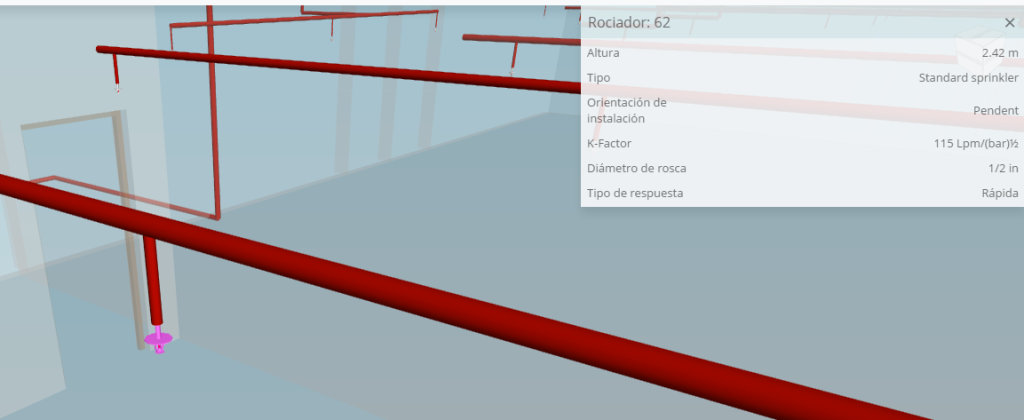
    Pipes that supply sprinklers directly or via hanging pipes.

  • Cross mains
    Pipes that supply the branch pipes, directly or via vertical pipes.

  • Riser
    Vertical pipes that supply cross mains via different floors.

  • Vertical pipe
    Vertical pipes that supply cross mains within the same floor.

  • Hanging pipe
    Vertical pipes that supply the sprinklers from the branch lines.

Vertical pipes

In the 2017.k version, the possibility was implemented to introduce risers to connect installations of different floor plans.

Now, in the 2018.f version, vertical spans can be introduced and edited within the same floor plan, with the purpose to avoid horizontal pipes colliding against other elements such as beams, air conditioning ducts, etc.

To do so, the option: “Vertical pipe” has been implemented. In the “Pipes” section of the top toolbar, the name of the option: “Riser” has been changed. Now, it is called “Vertical” and it contains “Risers” and the new option “Vertical pipe”.

To introduce vertical pipes, users must indicate the reference, pipes catalogue to use and the diameter. Then, the point of a horizontal pipe as of which the vertical pipe will begin must be selected. If two vertical pipes are introduced, it is possible to change the elevation of the horizontal span lying between the two vertical pipes.

Improvements in the generated installation project format

The presentation format of the project has been modified. The results are now displayed in a more clear and concise manner. The report of the seismic supports that have been introduced in the model is also included.

Seismic supports for sprinkler systems

To avoid the sprinkler systems from being damaged during an earthquake, the NFPA 13 code prescribes the use of seismic supports that resist the horizontal loads inflicted on the system. The 2018.e version of CYPEFIRE Sprinklers includes the introduction and check of seismic supports for the sprinkler system in accordance with the prescriptions of this code.

The NFPA 13 code classifies the seismic supports into 3 groups and can be introduced in CYPEFIRE Sprinklers from the “Support” menu of the toolbar:

  • Lateral support
    Prevents movement in the direction perpendicular to the pipe.
  • Longitudinal support
    Prevents movement in the direction parallel to the pipe.
  • 4-way support
    Prevents movement in the 4 directions.

Before introducing them, the main components of the seismic supports must be defined: fastenings, braces and anchors. Users can define, amongst other catalogues, the catalogues for fastenings, braces and anchors in the “General options” dialogue (“General options” menu of the toolbar). Standard catalogues, which are included in the program, can also be used and imported into projects to use directly or modify with user values.

  • Fastening
    This is the element that holds the pipe to the brace. To define it, users must simply complete the dimensions of this element for each fastening of the catalogue.
  • Brace
    This is the main element of the seismic support, consisting of a Schedule 40 pipe that has to resist the horizontal loads caused by the earthquake. To define it, users must introduce the length, diameter of the pipe and loads it can support at 30-44º, 45-59º and 60-90º.
  • Anchor
    The anchor is the part that keeps the support connected to the structure of the building. In this version of the program, the limits that have been applied are those of anchors to steel structures. In upcoming versions, anchors to timber or concrete structures will be added. To define them, the diameter of the anchorage bolt and load the anchor can resist for each type of assembly must be introduced.

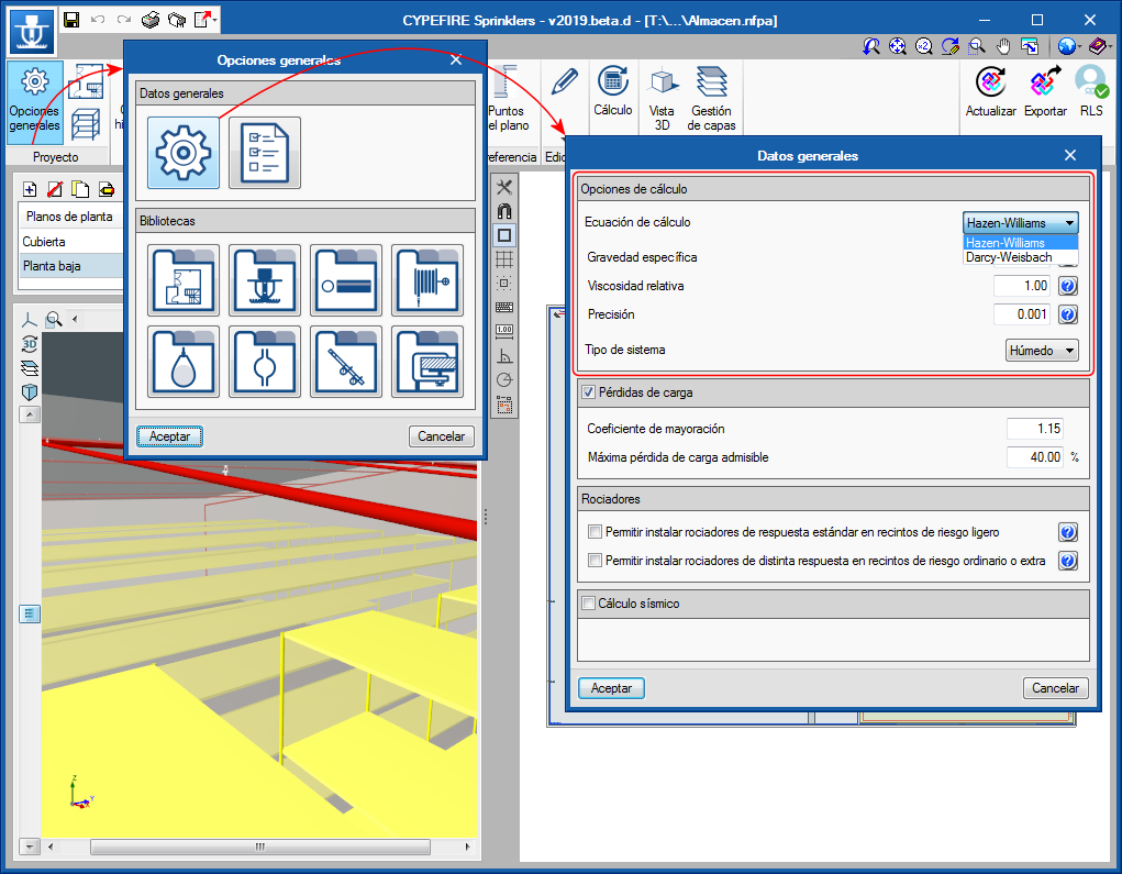
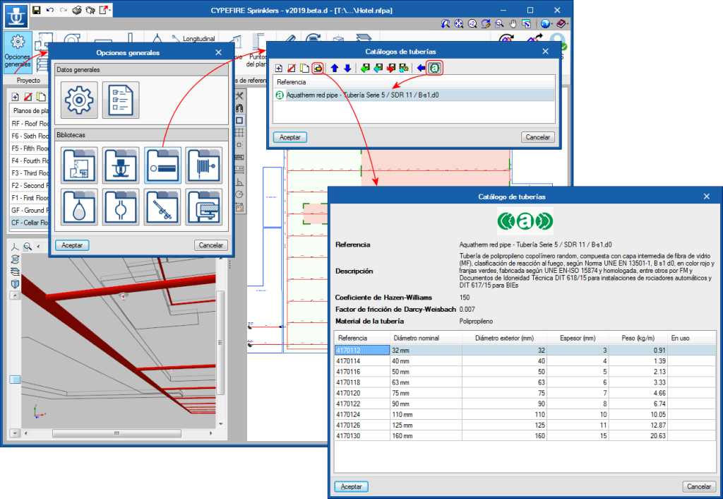
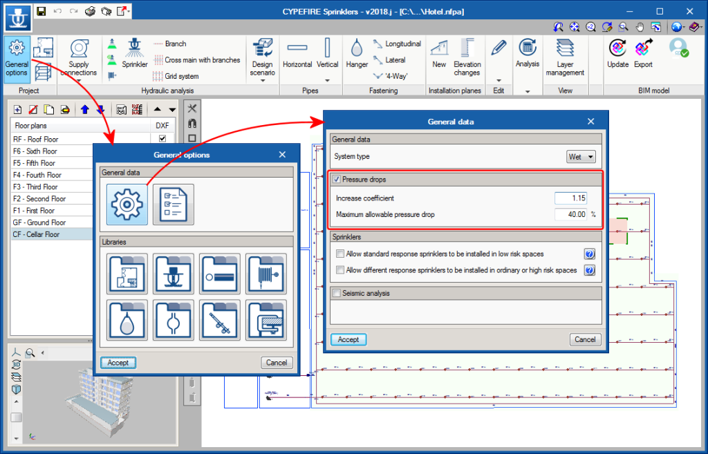
For CYPEFIRE Sprinklers to be able to carry out the required checks on seismic supports, the field “Weight per unit length” has been added to the pipe catalogues of the sprinkler systems (General options > Pipes catalogues) and the seismic coefficient Cp must be defined (General options > General data).

Once all the aforementioned elements have been defined, users must introduce each support that is going to be used at its corresponding position and define its influence zone, i.e. all the pipe spans that are to be held by each seismic support.

With the data indicated above, CYPEFIRE Sprinklers will ensure all the necessary checks are complied with for each type of support. The program generates the report required by the NFPA 13 code.

Improved interface

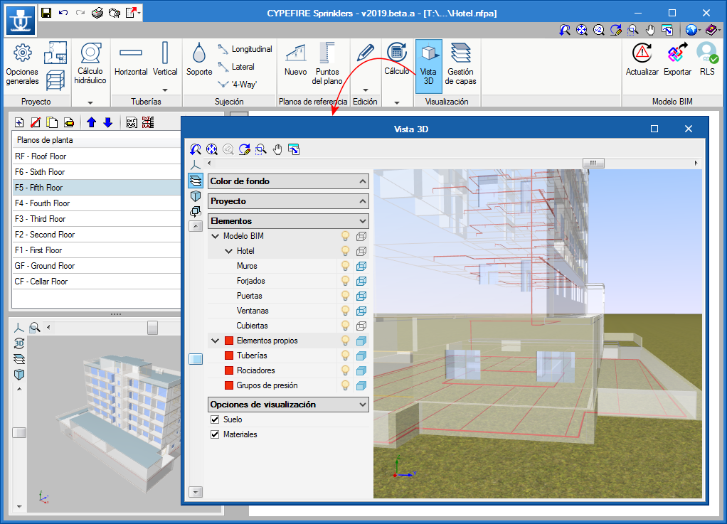
The 2018.e version of CYPEFIRE Sprinklers includes improvements in the organisation of its interface which also contains new tools to introduce seismic supports for the sprinkler systems.

Interface of earlier versions than the 2018.e version
Interface of the 2018.e version

The main differences are:

  • Project
    Now, all the libraries and configuration menus are located in General options. The “Distribution” menu also disappears and is relocated in the latter.
  • Installation elements
    This menu disappears and is divided into several menus. Now we can find:
    • Hydraulic analysis elements
      Located here are tanks, sprinklers, fire hoses and the tool to create design scenarios.
    • Pipes
      Includes risers and horizontal pipes.
    • Fastening
      Includes supports and seismic supports for pipes.

Program downloads on the BIMserver.center platform

AcoubatBIM by CYPE, CYPEPLUMBING Sanitary Systems, CYPEGAS, CYPEFIRE Sprinklers and CYPEFIRE CTE can be downloaded from the BIMserver.center platform.

These programs are also available in the general CYPE program menu that is installed when the complete download is carried out in the Download area of the CYPE website.

Supports for sprinkler systems

In the 2018.a version, it is possible to install supports to hold the load of the sprinkler systems. The quick and effective introduction of this type of supports, which is required for any type of installation, allows users to carry out the necessary checks to ensure that installation is done correctly, to obtain the justification of the individual checks of each support, detailed plans of the installation and material quantities, as well as the export to FIEBDC-3 to obtain the bill of quantities.

The introduction of the supports can be carried out by loading the catalogue offered by default by CYPEFIRE Sprinklers or by generating the user’s own catalogue of supports.

If users opt to generate their own catalogue, a standard series of data has to be specified, to define the “pear-type” support:

  • Nominal diameter of the pipe to support
  • Diameter of the threaded rod of the support
  • Geometric data of the support

Once the catalogue of supports has been defined, they are easily introduced. First the diameter of the pipe to support is defined, as is the material of the pipe and the distance between the supports that are going to be introduced. Then, all that must be done is to place them over the pipes and look through the individual checks of each support to ensure no errors exist.

With the data that has been introduced, CYPEFIRE Sprinklers will perform checks on all the supports and display a report with the following checks:

  • Maximum distance between hangers
    Depending on the nominal diameter and the material of the pipe, this separation could vary.
  • Diameter of the hanger rod
    Depending on the diameter of the pipe to be supported, the diameter of the threaded rod will vary.
  • Nominal diameters
    The program will ensure that the assembly being used is correct, avoiding large diameter pipes to be held by small supports.

Edit Menu

As occurs in CYPEFIRE CTE, the Edit section of the bar menu displays its elements in a floating menu which can be viewed in three different ways:

  • Horizontal with large icons
  • Vertical with large icons
  • Vertical with small icons and description texts of the tools

The floating menu can be pinned on screen so that the options remain visible when others are being used. It can also be placed to the side of the workspace so it resembles a toolbar.

This type of menu is the same as that which was implemented in the 2017.j version for CYPETHERM HVAC and StruBIM foundations (see the Floating tools section of the new features of the 2017.j version) and in this version (2017.k) for IFC Builder.

Additionally, the following tools have been added to this menu for CYPEFIRE Sprinklers:

  • Assign
    This tool, already known in other programs, allows users to quickly assign the same properties to different sprinklers or pipes. Once the option has been selected, users click on the element to which its properties are to be copied and an editing panel appears with its data. After the panel has been accepted (in which users can modify data), another element or other elements can be selected (one by one or using a selection window). Once all the elements to which the properties of the panel are to be copied have been selected, a right click on the mouse button confirms the action to copy the properties.
  • Measure lengths on plan
    Allows users to quickly make on-screen measurements.
  • Move tag
    When an installation consists of a complicated arrangement of pipes, it may be difficult to view references, diameters and nodes clearly. Now, these tags can be displaced by users to obtain clear and more effective plans.
  • Show/hide tag
    For the same reason as indicated for the option above, there may be irrelevant information hindering a correct view of the drawing, hence users can also show or hide tags.
  • Tag line
    If, having displaced a tag, it is difficult to see to which element it refers, it is possible to draw an auxiliary line using this tool which links the tag directly to the reference element.
  • Insert text
    Allows users to introduce text on the interface to provide further information on the installation. This text can be printed in the drawings.

Racks

The 2017.k version of CYPEFIRE Sprinklers includes racks, an important element when designing a sprinkler system.

The racks pose a challenge for designers because the type of installation to be executed depends on their geometry and what they store.

In this version, users define the height of the racks and their geometry on plan, which will then be used by the program to carry out the necessary checks on the ESFR sprinklers. More information on the racks can be implemented in future versions, such as the type of material that is stored (Class I to IV, rubber tyres, etc.) the geometry of the rack (solid shelving, palletized racks, portable racks, etc.) and the introduction of sprinklers at each level of the rack (In-Rack sprinklers).

ESFR – Sprinklers

The 2017.k version includes a new type of sprinkler: ESFR (Early Suppression Fast Response).

The main properties of this sprinkler are its fast response and its discharge factor, K, which is greater than 11.2 gpm/psi1/2 (160 lpm/bar1/2). It is known for its great capacity to suppress fire and its use in high risk zones. These sprinklers are usually used to avoid having to include In-Rack sprinklers in the installations.

3D geometry. Risers

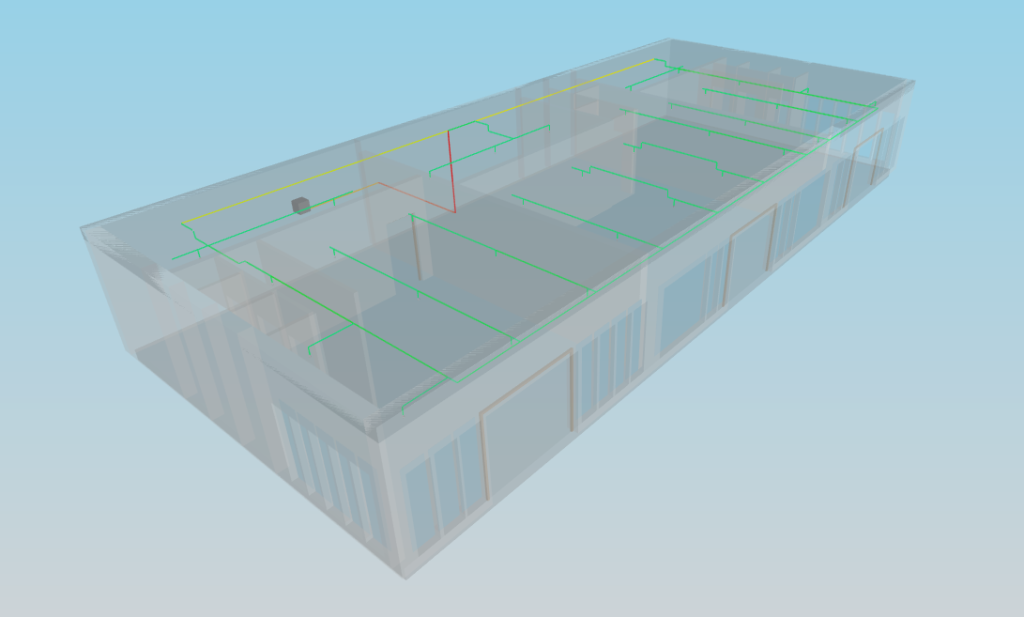
As of the 2017.k version of CYPEFIRE Sprinklersrisers can be used as vertical connections between pipes of different floors.

For this initial implementation, it is only possible to use risers if users link their project to a BIM model (even if the connection with the model is not maintained and only its 3D geometry is conserved). This feature will be further developed in future versions, where it will be possible to introduce risers without requiring the connection with the BIM model and users will have a palette of options regarding their definition, such as being able to introduce sloped risers.

Risers are located in the “Pipes” menu. Users must define the reference, material and size to be used. Once the riser has been introduced on the floor plan, it will be displayed in a lighter colour (transparent layer) on the other floors. The riser has to be introduced on all the floor plans where it will be connected to horizontal pipes. When it is introduced on other floors, it is displayed in a darker colour (the same way as occurs on the floor plan where it was first introduced).

Risers are also included in the reports and are clearly identified in the nodes lists with the reference: “Riser node”.