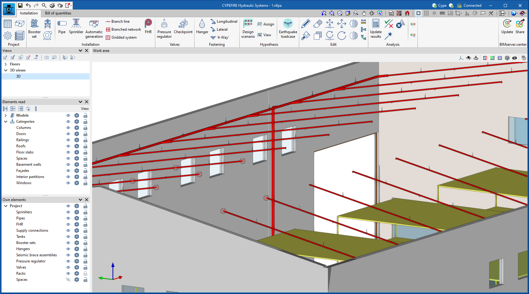
Update history​

CYPEFIRE Hydraulic Systems

64-bit Version

As of the 2019.f version, CYPE programs (those downloaded from our website and those downloaded from the BIMserver.center platform) are compiled for 64-bit systems. The 64-bit compilation of CYPE software implies the use of the superior features of 64-bit processors and operating systems compared to those of 32 bits.

Please bear in mind that you must have a 64-bit operating system to be able to work with any 64-bit software.

In any case and as a temporary measure, the 2019.f version is available in 64 and 32 bits on the download area of our webpage. The programs that can be downloaded from the BIMserver.center platform are only available in 64 bits. If you have a 64-bit operating system, you can work with either the 64-bit and 32-bit version of our software, although we strongly recommend that you install the 64-bit CYPE software version.

You can see which operating system is installed on your computer by clicking on "Control panel > System".

Since 64-bit microprocessors began to be massively introduced into personal computers from 2003 and from the Windows XP version, Microsoft already offers the two versions of its operating systems (32 and 64 bits). We understand that almost all our users will have computers with 64-bit processors (x64) and 64-bit operating systems.

It could occur that a user may wish to work with a computer with a 64-bit processor but with a 32-bit operating system. It would be very strange if the computer had a 32-bit processor (x86 - computers over 15 years old). If any of these is your case, we advise you to talk to your hardware or software provider to update your situation as soon as possible. However, you can download the 32-bit version and work with CYPE programs that can be downloaded from our website until your situation is up-to-date.

Notification of the requirement to have an automatic fire extinguishing installation

The way in which the requirements of an automatic fire extinguishing installation are notified for projects coming from CYPEFIRE Design and CYPEFIRE CTE has been updated.

Now, when users have defined a sprinkler installation in the previously mentioned applications, but it has not been defined in CYPEFIRE Sprinklers, an error will appear in the space in which it is lacking, warning of its inexistence and the program that has foreseen it.

When CYPEFIRE Sprinkler users introduce the automatic extinguishing installation, the error message, although in the information of the space, the program that has foreseen the requirement remains and informs the user whether it has been fulfilled.

Design method. Selection of the equation to calculate the pressure loss

The 2019.d version of CYPEFIRE Sprinklers allows users to select the pressure loss equation, either the “Hazen-Williams” or “Darcy-Weisbach” method, to apply when the sprinkler installation is analysed.

Upon selecting the pressure loss equation, other properties are defined, such as:

  • Specific gravity
    Ratio of the density of the fluid with respect to that of water at 4°C.

  • Relative viscosity
    Ratio of the kinematic viscosity of the fluid with respect to that of water at 20°C.

  • Precision
    Convergence criteria used to indicate that the solution to the non-linear equation has been found. The iterations end when the sum of all the changing flows divided by the sum of all the line flows is less than this number.

The Hazen-Williams analysis method is one of the most used methods due to its simplicity, but cannot be used for liquids other than water. The Darcy-Weisbach method, however, is more precise but more complex, because the friction factor has to be calculated. All these options can be edited and are located in the “General data” panel.

“Aquatherm Red Pipe” pipes catalogue

The 2019.d version of CYPEFIRE Sprinklers now includes Aquatherm’s “Aquatherm Red Pipe” catalogue in its pipes library.

The catalogue that has been introduced for the design is that of Aquatherm Red Pipe fire safety pipes, which consist of polypropylene random copolymer pipes, with an intermediate fibreglass layer, with a fire reaction classification, in accordance with UNE EN 1351-1, B s1 d0, red with green strips, manufactured in accordance with UNE EN-ISO 15874, with Technical Suitability Evaluation, in accordance with the “Reglamento de Instalaciones de Protección contra Incendios” RIPCI 2017, and homologated, amongst others, by FM, Technical Suitability Documents DIT 618/15 for installation with automatic sprinklers and DIT 617/15 for fire hose reels.

The Aquatherm catalogue can be incorporated into the project by selecting the Aquatherm logo located in the top part of the “Pipes catalogue” panel, and the import is carried out in the same way as for the other catalogues. Once imported, the data cannot be edited, as is done with the generic pipes catalogues, but their properties can be seen.

Reading of suspended ceilings defined in the BIM model

Open BIM Suspended ceilings (new program implemented in this version) exports the layout of the suspended ceilings of the project to the BIM model. Also in this version, CYPEFIRE Sprinklers can read the panels of the suspended ceilings from the BIM model and show them as a template in the floor plans of the project.

Thanks to this, users can view the position of the suspended ceilings on the floor plan and introduce the sprinkler system installation avoiding any collisions with the support elements of the suspended ceilings of the accessible panels.

Their visibility can be deactivated in “Layer management”, so not to hinder users in more advanced design phases.

3D view

The 2019.a version of CYPEFIRE Sprinklers includes the "3D View" button in the main menu of the program. This tool shows the 3D view of the BIM project in a new window. This 3D view is the same view that appears in the lower left-hand area of the screen, but the configuration of the visible elements and their perspective are independent in both views.

Equipment information in the 3D viewer of BIMserver.center

As of the 2019.a version, CYPEFIRE Sprinklers exports, to the BIM model, data on the elements used in the fire safety installation from the sprinklers that it designs. This data is included in a “.GLTF” format file that is used to show the model 3D both in the viewer that is integrated in the BIMserver.center web platform and in its application for mobile devices -App.

Thanks to this new feature, BIM project collaborators can obtain the following information regarding the elements that have been introduced in the project:

  • Sprinklers
    Reference, height, type, orientation and K-factor.
  • Pipes
    Reference, material, diameter and roughness.
  • Supports
    Reference, diameter and height.
  • Seismic supports
    Reference, angle at which it is placed and supported load.
  • Tanks
    Reference and volume.

Contour map diagrams of pipes in the 3D viewer of BIMserver.center

When the export is carried out from CYPEFIRE Sprinklers to the BIM project, the generated IFC file can optionally include several "gltf" files that contain the contour map diagrams of each result (flow rate, velocity, pressure losses...) in the three-dimensional view.

This allows users to visualise the contour maps in the 3D viewer of BIMserver.center, in the same way as was already done in other Open BIM applications such as CYPETEL Wireless or CYPELUX. These "gltf" files are independent of what was already generated for the sprinklers installation, so each of them can be viewed independently in the 3D viewer of BIMserver.center.

Contour map diagrams with pipe data

As of the new 2019.a version, CYPEFIRE Sprinklers includes a graphical representation of the data calculated using contour map diagrams on the pipes of the installation.

The representation of the results using contour maps is activated and configured in the program using two options that are included in the “Analysis” menu:

  • Graphical analysis of the results
    This option activates the graphical representation using contour map values on the sprinkler system, which allows for the following results, which are obtained from the application, to be seen:
    • Flow
    • Velocity
    • Pressure loss
    • Length
    • Height
  • Range of results for the graphical analysis
    This option allows users to define specific analysis intervals, so the program will only graphically represent the data that lies within each range.

This tool allows users to carry out a quick analysis of the sprinkler installation. For example, it is possible to instantly view where large pressure losses are being produced to design the network.

Reference drawings of the installation

The 2018.j version of CYPEFIRE Sprinklers contains two tools that allow users to define sprinkler installations with different installation planes, horizontal and sloped (such as sprinkler systems parallel to sloped roofs) more quickly and comfortably.

To do so, two new options have been included (“New” and “Elevation changes”) in a new section of the top tool menu (Installation planes):

  • New
    Allows users to quickly define a reference plane of the installation by introducing its outline, a reference and a height above the level of the floor that is currently being viewed. Users can define as many planes as they wish.

    Sprinklers and pipes that are to be placed in one of the planes that has been defined, must have the “Place the element in the reference plane of the installation” option marked (a new option of the panel that opens when a pipe or sprinkler is introduced) and then position them in the desired plane.

  • Elevation changes
    Using this option, users can define sloped reference planes. A horizontal reference plane must first be defined using the previous option. Then, using the “Elevation changes” option, three points are to be marked on the reference plane, indicating their elevation, which will define the corresponding sloped plane.

Automatic save

Two options regarding the automatic save of the project have been implemented (Configuration  > Automatic saving options). There are two options that can be activated individually or simultaneously.

  • Automatically save every “x” minutes
    Saves the project automatically each time the indicated period has passed.
  • Save after analysing or designing
    Saves the project automatically when the installation is designed.

Pressure drops

As of the 2018.i version, CYPEFIRE Sprinklers contains two new options for the hydraulic analysis which allows users to calculate any pressure drops in a more precise and controlled manner.

In the “General data” menu, the option, Pressure drops, has been added, which can be deactivated if these considerations are not to be taken into account. When it is activated, two options appear:

  • Increase coefficient
    This is a safety coefficient that the program applies to the existing pipe lengths of the program to simulate the pressure drops due to specific elements such as elbows, intersections, T-connections, valves, etc.

    The value provided by default is 1.15 and represents a pressure drop of 15%.

  • Maximum allowable pressure drop
    Is the maximum allowable pressure drop produced at any span of the pipe. If the difference in pressure between the initial and final node is greater than the indicated value, a warning will be displayed on the pipe to indicate that it must be redesigned.

    This option allows users to rapidly detect spans which, due to their dimensions, produce large pressure drops and must be redesigned. The default value is 40%.