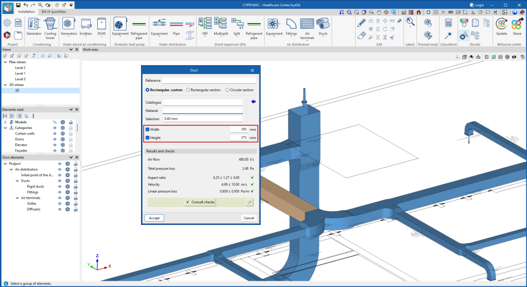
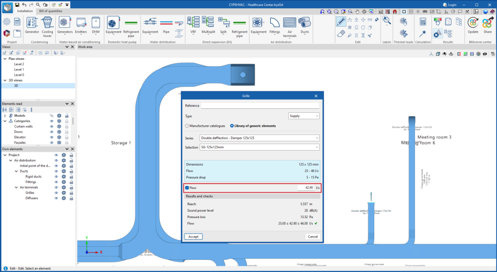
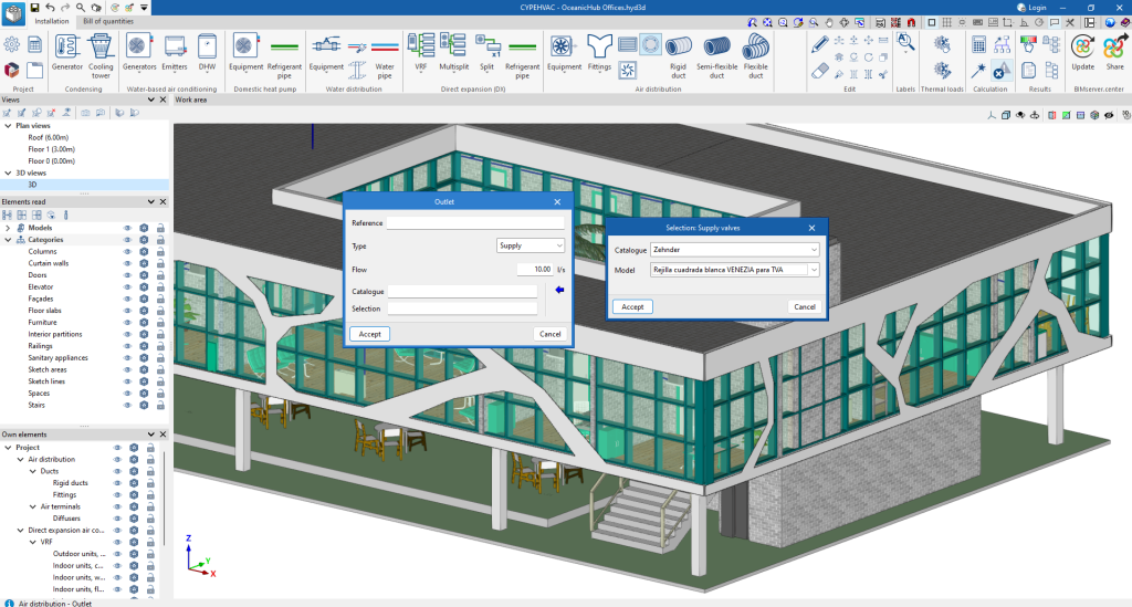
As of version 2025.c, in CYPEHVAC users can force the dimensions of the air ducts and the flow rates of the terminal elements.
Update history
CYPEHVAC
New options for defining ducts and grilles
- Published on
- 2025.c
Defining the maximum number of decimal places
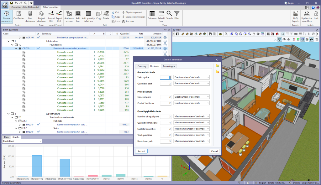
In version 2025.c, an option has been added to configure the display of significant decimals in the "Bill of quantities" tab in the apps. This new feature is used to adapt the level of numerical precision to the specific needs of each project, providing greater flexibility in the presentation of the data.
To define this configuration, a drop-down menu has been added in the "General parameters" > "Decimals" section, next to the number of decimals in each field, with the following options:
- Exact number of decimals. Displays all decimals, regardless of whether they are significant figures or not. This option, which is the one used in previous versions, is kept as the default for new projects.
- Maximum number of decimals. Limits the display to significant figures, up to a user-specified maximum number of decimal places. This option allows for better control of the accuracy of the data, which simplifies the presentation of the information.
This configuration is compatible with the FIEBDC-3 (.bc3) standard, to ensure that adjustments made to the number of decimal places can be read and exported correctly by the data exchange tools available in the app.
- Published on
- 2025.c
Transparent preview in dockable windows
In version 2025.c, the preview for moving dockable windows within the apps has been improved. Now, when dragging a dockable window, the preview of its docked position is displayed transparently, allowing a clearer view of the underlying work area.
This new feature makes it easy to find the optimal location for each dockable window without obstructing important elements or losing sight of relevant project information. It also provides a smoother and more modern visual experience, aligned with best practices in user interface design.
- Published on
- 2025.c
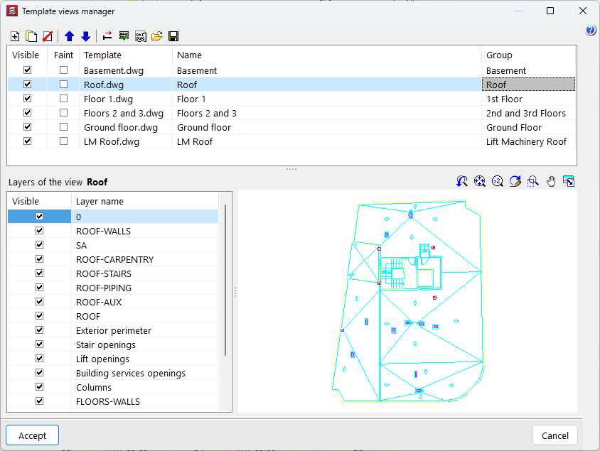
Improved management of DXF and DWG templates
Version 2025.c of the CYPE apps includes the following improvements in the management of DXF and DWG file templates:
- Reading DXF/DWG files with updated version
As of version 2025.c, CYPE apps can read DXF/DWG files up to AutoCAD® version 2025.
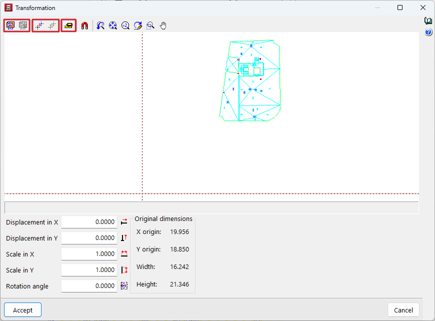
- Improved template preview
Advanced graphic management has been implemented in the template selection and transformation panels to optimise the template drawing preview window and facilitate the movement of the drawing from this panel.
- Arquimedes, CYPE 3D, CYPE Gas Supply, CYPE Sewerage, CYPE Water Supply, CYPECAD, CYPEFIRE, CYPEFIRE FDS, CYPEFIRE Hydraulic Systems, CYPEFIRE Pressure Systems, CYPEHVAC, CYPEHVAC Radiant Floor, CYPEHVAC Schematics, CYPELEC Distribution, CYPELEC Electrical Mechanisms, CYPELEC PV Systems, CYPELUX, CYPEPLUMBING, CYPETHERM EPlus, CYPETHERM LOADS, Open BIM Analytical Model, Open BIM Cable Routing, Open BIM Quantities, Open BIM Switchboard, StruBIM Box Culverts
- Published on
- 2025.c
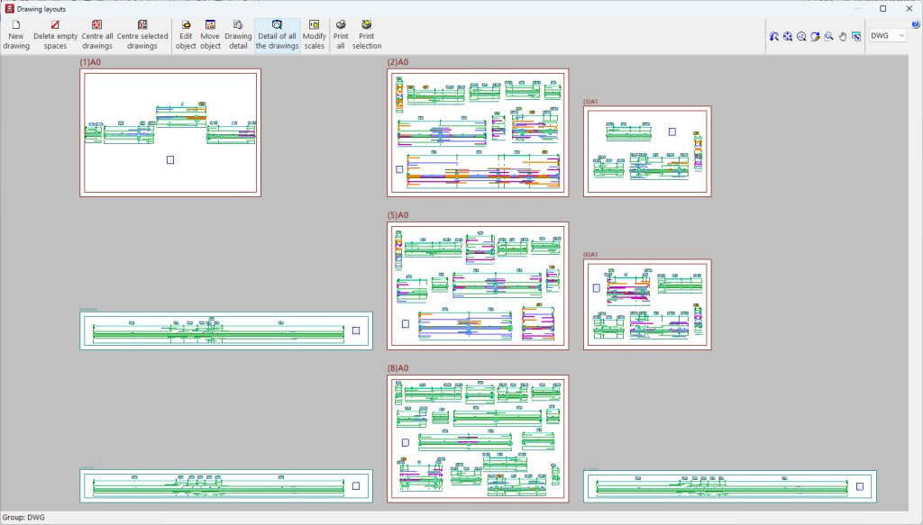
Use of hardware acceleration in the drawing tool
As of version 2025.c, the "Drawing layouts" panel uses hardware acceleration for drafting drawings. This implementation allows users to represent and move the model more smoothly.
This panel is present in several CYPE programs, although hardware acceleration is much more noticeable in programs and projects with multiple elements (CYPECAD, CYPE 3D, CYPECAD MEP, etc.).
- Continuous beams, CYPE 3D, CYPE Gas Supply, CYPE Sewerage, CYPE Water Supply, CYPECAD, CYPEFIRE, CYPEFIRE FDS, CYPEFIRE Hydraulic Systems, CYPEFIRE Pressure Systems, CYPEHVAC, CYPEHVAC Radiant Floor, CYPEHVAC Schematics, CYPELEC, CYPELEC Distribution, CYPELEC Electrical Mechanisms, CYPELEC MULTILINE, CYPELEC Networks, CYPELEC PV Systems, CYPEPLUMBING, CYPETEL Wireless, CYPETHERM EPlus, CYPETHERM LOADS, Open BIM Analytical Model, Open BIM Cable Routing, Open BIM Switchboard, Portal frame generator, StruBIM Box Culverts, StruBIM Cantilever Walls, StruBIM Deep Beams, StruBIM Embedded Walls, StruBIM Shear Walls
- Published on
- 2025.c
Plenums for outlets
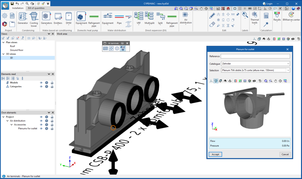
CYPEHVAC now includes the possibility of inserting plenums for outlets in duct systems.
In version 2025.b, outlets were added to the program; now, in this new version 2025.c, these outlets can also be entered in the plenums for outlets.
From the "Catalogue management" option, different plenum manufacturer's catalogues can be downloaded. These new catalogues, incorporated in this version, contain the 3D drawing with the plenum geometry, as well as the plenum connections and their analysis data.
These elements can be used by the user in the installation from the "Plenum for outlet" option in the "Air terminals" section.
- Published on
- 2025.c
Plenums
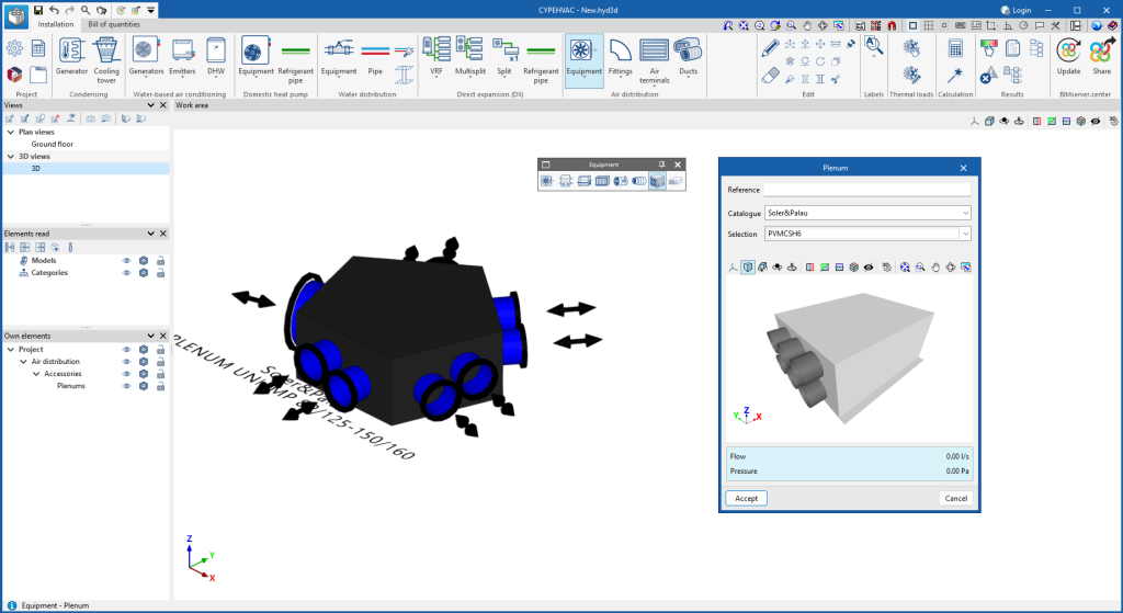
In version 2025.c, the possibility of entering plenums in duct systems has been included.
From the "Catalogue management" option, different plenum manufacturer's catalogues can be downloaded. These new catalogues, incorporated in this version, contain the 3D drawing with the plenum geometry, as well as the plenum connections and their analysis data.
These elements can be used in the system from the "Plenum" option in the "Equipment" section.
- Published on
- 2025.c
Improvements in VRF systems
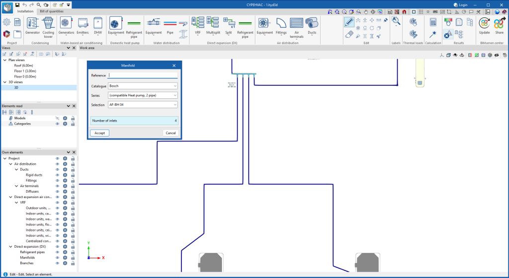
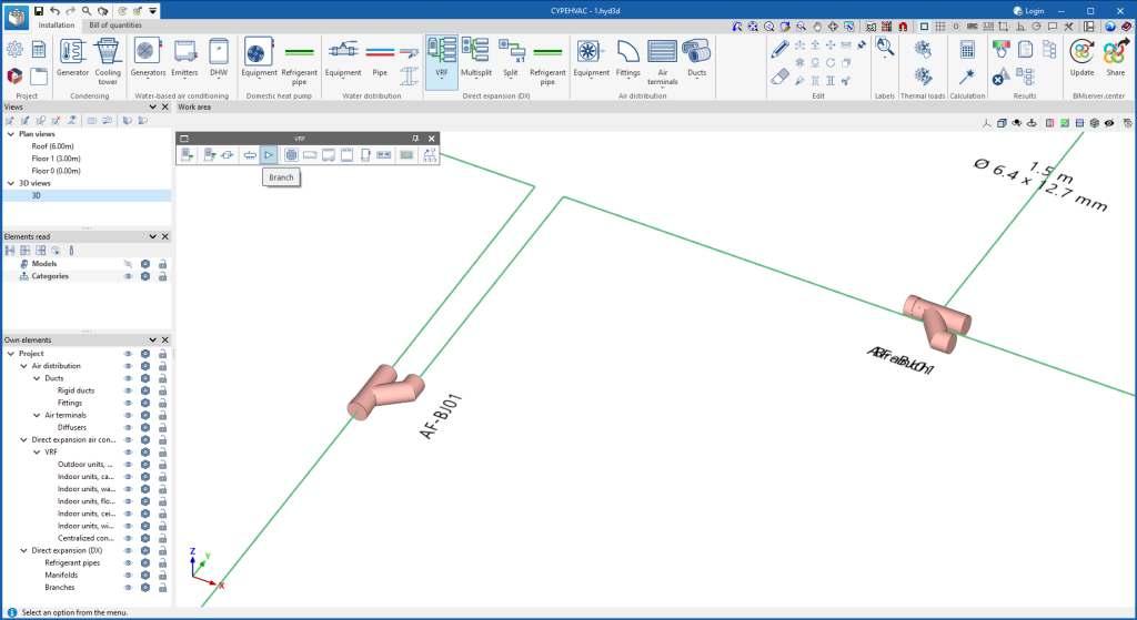
In CYPEHVAC version 2025.c, manifolds for distributing VRF systems have been added. As a result, branches with more than two outlets can be designed.
- Published on
- 2025.c
Hydraulic bibloc air-source heat pump system
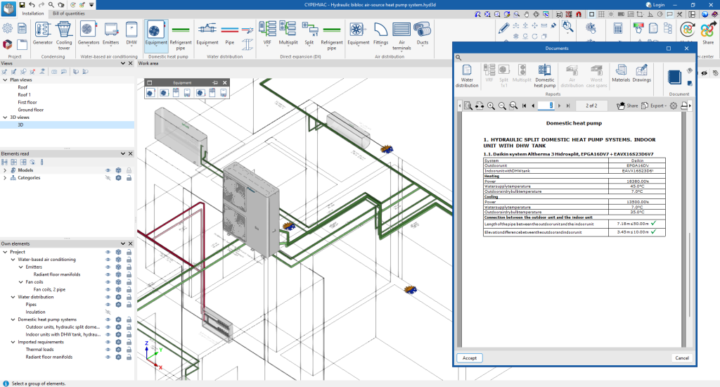
Within the air-source heat pump units, the CYPEHVAC version 2025.c has added the hydraulic bibloc system. This system consists of a compact outdoor unit and an indoor unit containing the hydraulic components of the system, connected by water pipes. These units can be found in the Bosch, Daikin, Mitsubishi Electric, Panasonic, Saunier Duval and Vaillant aerothermal system catalogues, available in the "Catalogue management" option.
The layout of the hydraulic bibloc air-source heat pump system works in a similar way to the bibloc air-source heat pump system. The selection of the set (outdoor unit and indoor unit) is made on the panel of the indoor unit, from which the water-based air-conditioning system inside the building starts. Furthermore, the primary circuit can be laid out by placing the outdoor unit in the work area and connecting it to the indoor unit by means of water pipes. In this case, the pipe length, height difference and pipe diameter limits established by the manufacturer for the primary circuit shall be checked.
- Published on
- 2025.c
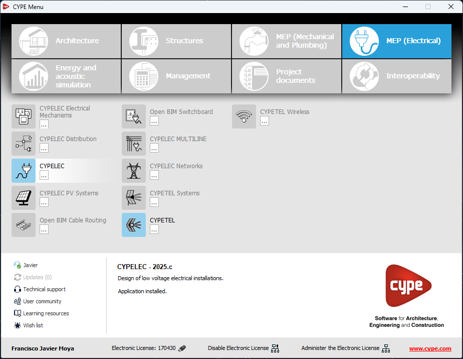
Changes to the apps available in CYPE Menu
The following modifications have been made to the apps available in the CYPE Menu:
New apps
- Now, in addition to the apps that are translated into the installation language of the CYPE Menu, there are also apps available in English.
Deleted apps
- CYPEPLUMBING Solar Systems. Integrated in CYPEPLUMBING.
- CYPETEL Schematics. Replaced by CYPETEL.
- CYPELEC Grounding IEC and CYPELEC Grounding IEEE. Integrated into CYPELEC and CYPELEC Distribution.
- AcouBAT by CYPE, Arquimedes, Construction details library for structures, Continuous beams, CYPE 3D, CYPE Architecture, CYPE Connect, CYPE Connect Classic, CYPE Construction Systems, CYPE Cost Estimator, CYPE Gas Supply, CYPE Sewerage, CYPE Water Supply, CYPECAD, CYPEFIRE, CYPEFIRE FDS, CYPEFIRE Hydraulic Systems, CYPEFIRE Pressure Systems, CYPEHVAC, CYPEHVAC Radiant Floor, CYPEHVAC Schematics, CYPELEC, CYPELEC Distribution, CYPELEC Electrical Mechanisms, CYPELEC MULTILINE, CYPELEC Networks, CYPELEC PV Systems, CYPELUX, CYPEPLUMBING, CYPESOUND, CYPETEL Wireless, CYPETHERM BRIDGES, CYPETHERM C.E., CYPETHERM EPlus, CYPETHERM HYGRO, CYPETHERM LOADS, IFC Builder, Open BIM Analytical Model, Open BIM Cable Routing, Open BIM Layout, Open BIM Model Checker, Open BIM Quantities, Open BIM Site, Open BIM Switchboard, Plugin Open BIM - Revit, Portal frame generator, Punching shear verification, StruBIM Box Culverts, StruBIM Cantilever Walls, StruBIM Deep Beams, StruBIM Embedded Walls, StruBIM Shear Walls, StruBIM Steel
- Published on
- 2025.c
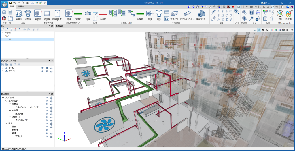
Installation in Japanese
- Published on
- 2025.b
Supply valves and exhaust valves
In this new version, the air terminals available in CYPEHVAC have been extended with the addition of supply and exhaust valves.
These elements are mainly used in controlled mechanical ventilation (CMV) systems.
Users can incorporate these elements into the system from the "Outlet" option in the "Air distribution" section, available once a manufacturer's catalogue has been downloaded via the "Catalogue management" button.
- Published on
- 2025.b


