Update history​

CYPELEC Networks

Font size

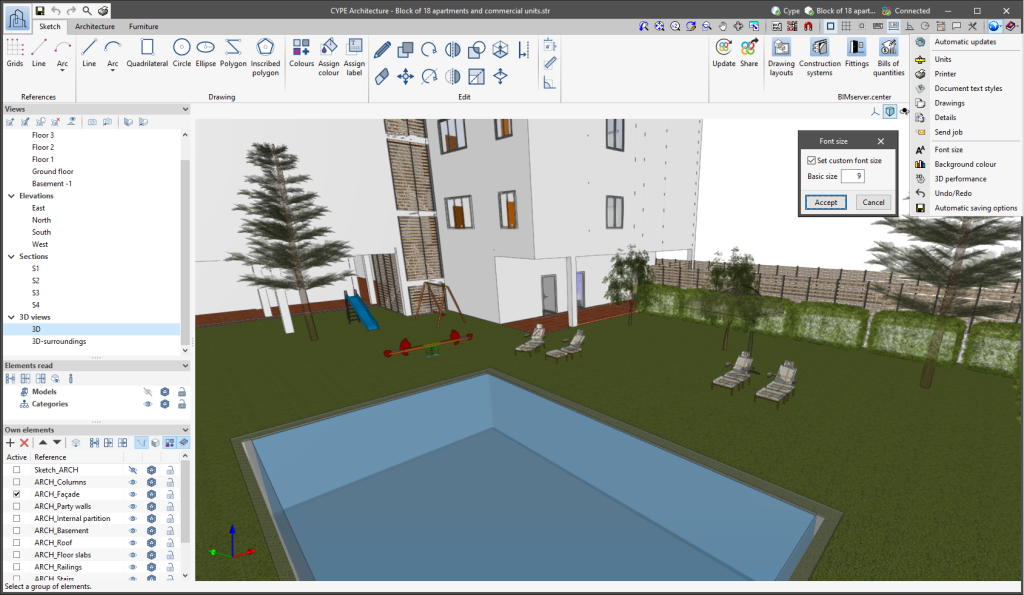
The "Font size" option has been added to the general configuration menu of the applications. This tool allows users to increase or decrease the basic size of the font used in the user interface of the programs. Thanks to this implementation, the accessibility of the applications has been improved while also ensuring the correct visibility of the content on devices with different screen resolutions.

To enter a "Basic size" the "Set custom font size" option must be checked. The size users can enter is the application's basic font size. Any other font sizes that may exist in the program's interface will be automatically modified proportionally according to the change in the basic size.

It is important to note that, as this is a common parameter, its modification will affect all installed CYPE tools.

Phase names in a three-phase system

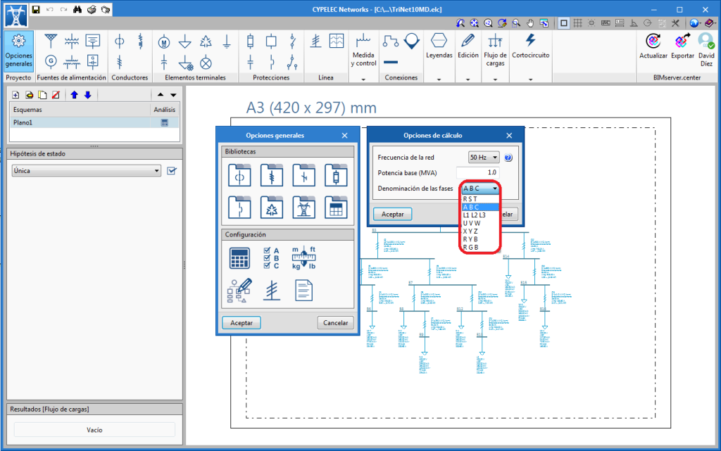
The 2020.b version of “CYPELEC Networks” contains new ways to identify and distinguish the three phases of a three-phase electrical system.

Export the circuit drawing to the BIM project

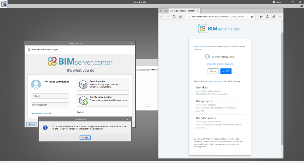
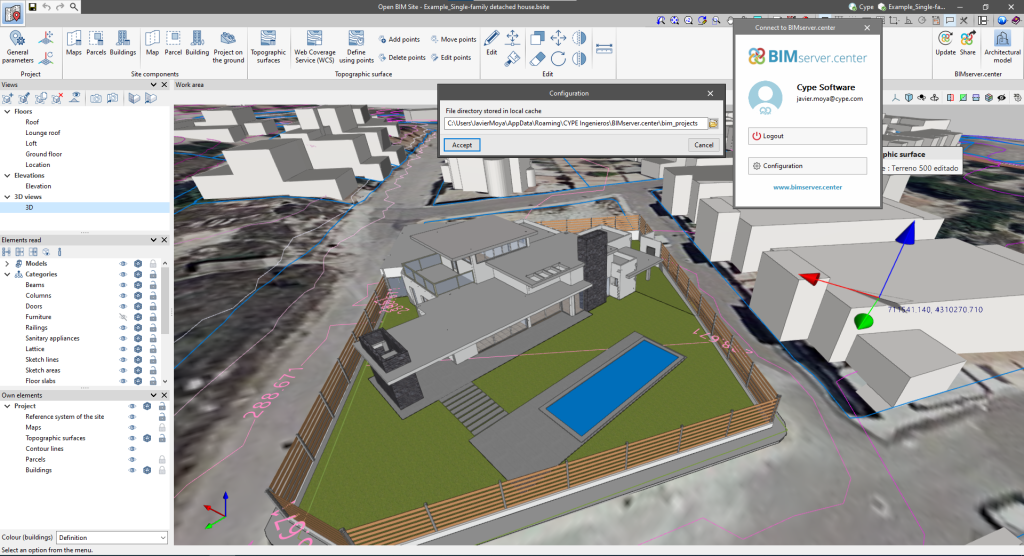
As of the 2019.f version, CYPELEC Networks allows users to export the circuit drawing to the BIM project located on BIMserver.center. This drawing includes the results of the load flow analysis and short-circuit calculations.

64-bit Version

As of the 2019.f version, CYPE programs (those downloaded from our website and those downloaded from the BIMserver.center platform) are compiled for 64-bit systems. The 64-bit compilation of CYPE software implies the use of the superior features of 64-bit processors and operating systems compared to those of 32 bits.

Please bear in mind that you must have a 64-bit operating system to be able to work with any 64-bit software.

In any case and as a temporary measure, the 2019.f version is available in 64 and 32 bits on the download area of our webpage. The programs that can be downloaded from the BIMserver.center platform are only available in 64 bits. If you have a 64-bit operating system, you can work with either the 64-bit and 32-bit version of our software, although we strongly recommend that you install the 64-bit CYPE software version.

You can see which operating system is installed on your computer by clicking on "Control panel > System".

Since 64-bit microprocessors began to be massively introduced into personal computers from 2003 and from the Windows XP version, Microsoft already offers the two versions of its operating systems (32 and 64 bits). We understand that almost all our users will have computers with 64-bit processors (x64) and 64-bit operating systems.

It could occur that a user may wish to work with a computer with a 64-bit processor but with a 32-bit operating system. It would be very strange if the computer had a 32-bit processor (x86 - computers over 15 years old). If any of these is your case, we advise you to talk to your hardware or software provider to update your situation as soon as possible. However, you can download the 32-bit version and work with CYPE programs that can be downloaded from our website until your situation is up-to-date.

Incorporation of Prysmian medium voltage cable families

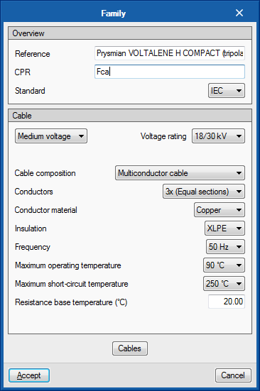
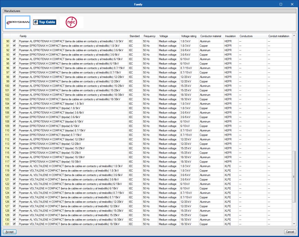
Several families of medium/high voltage Prysmian cables are included, specifically for 1.8/3 kV, 3.6/6 kV, 6/10 kV, 8.7/15 kV, 12/20 kV, 15/25 kV and 18/30 kV voltages, in copper and aluminium, with XLPE and HEPR insulation and three-core and touching cable configurations.

Edit, in series, elements belonging to the same class

The “Edit series” tool has been implemented to edit, in series, elements belonging to the same category.

The tool is located in the “Edit” section of the toolbar.

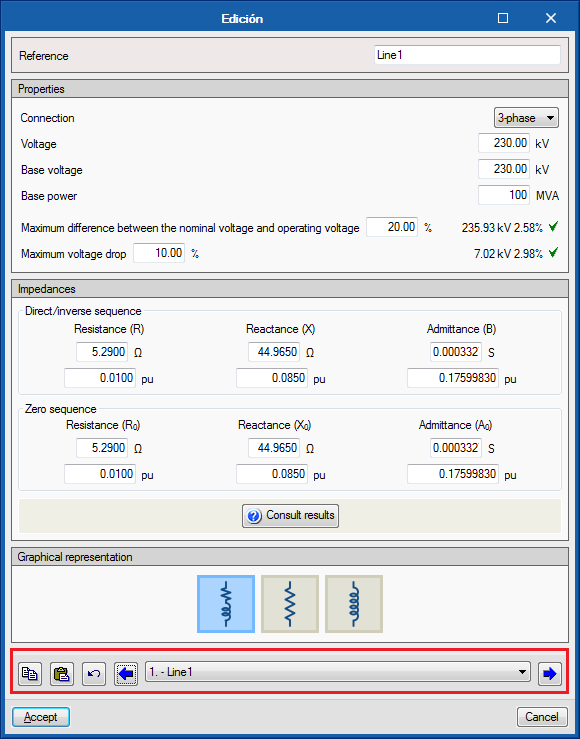
If the “Edit series” tool is active when any element of the single-line diagram is edited, for example an impedance, the editing panel that appears has a lower bar that allows to scroll through (backwards and forwards) all the elements of the same category that are present in the single-line diagram. This tool also allows you to copy the editing parameters of the element that is being viewed and paste them onto another previous or subsequent element.

The “Edit series” tool has been created for quicker editing and viewing of the properties of the elements of the circuit diagram.

French, Italian and Portuguese versions

CYPELEC Networks has been translated into French, Italian and Portuguese, hence, once downloaded from the BIMserver.center platform, the program can be installed in these languages, as well as in English or Spanish, which were available when the program was launched.

Connection between CYPELEC Networks and CYPELEC Core, CYPELEC NF and CYPELEC REBT

CYPELEC Core, CYPELEC NF and CYPELEC REBT design low voltage installations. In previous versions of CYPELEC Networks, users had to manually introduce the loads that correspond to the low voltage installations (calculated in the aforementioned programs), which are supplied by the medium or high voltage network, and were going to be analysed in CYPELEC Networks.

As of the 2019.b version, and thanks to the Open BIM connection of these programs, CYPELEC Core, CYPELEC NF and CYPELEC REBT can export the demanded or foreseen power (power and power factor) that is required by the installations they design to the BIM model.

This way, when a project is begun in CYPELEC Networks, by connecting to the BIM model to which the demands of the installations that have been designed in CYPELEC Core, CYPELEC NF and CYPELEC REBT have been exported, CYPELEC Networks users will be able to import the IFCs that are generated by the programs and will decide which loads will be part of the high or medium voltage diagram.

To select these loads, CYPELEC Networks has a new tool represented by Carga importada, located in the “Terminal elements” section of the toolbar.

When this tool is selected, the program allows users to select the desired load among those imported from the BIM model to include it in the diagram and continue with the electrical installation. Each time this tool is selected, one of the imported loads can be selected.

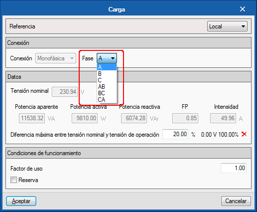
If the imported load is single-phase, it will be possible to select to which phase is connected.

In the project, imported loads can be combinedand user can introduce their own loads created directly in CYPELEC Networks.

Export the single line diagram to the BIM model and reading of the diagram in CYPELEC Multiline

CYPELEC Networks exports the single-line diagram to the BIM model using a file in IFC format. This file can be imported by "CYPELEC Multiline" from the "BIMserver.center" platform to represent the multiline diagram of the installation.

Status column in the diagrams list

When the load flow or short circuit analysis is launched, all the diagrams of the project are designed, not only the one that is active.

To represent the final design status, a column is added to the right of the diagrams, so users can quickly view the result.

New editing tools (Rotate group and copy to another diagram)

In the “Edit” block of the CYPELEC Networks toolbar, two new options have been added: “Rotate group” and “Copy to another diagram”:

  • Rotate group
    Allows for several elements to be captured at once and then rotated.
  • Copy to another diagram
    Allows for one or several elements of a diagram to be selected then copied to another diagram. This tool works in a similar way to copying between floors of other CYPE programs.

Quick connection introduction

Since previous versions, the “Connections” tool had to be selected from the top menu of the program window to be able to connect elements that have been introduced in the installation (transformer, supply connection, cable, transmission line, impedance, load...).

As of the 2019.a version, the connection procedure of the elements that are introduced in the installation has been improved. Now, if the right mouse is pressed after entering an element, the "Connections" tool is activated automatically without the need to move the mouse to select this tool in the top menu.