Update history
- Solutions
- CYPETHERM HVAC
- Update history
CYPETHERM HVAC
Aerothermal technology uses a heat pump system that produces hot water for heating and sanitary hot water, with the option to inverse the cycle for cold water.
The 2017.j version of CYPETHERM HVAC incorporates the Toshiba Estia aerothermal system. Estia is a split system that consists of an indoor unit and an outdoor unit, with a possible sanitary hot water accumulator. This system can be included in the flow diagram, or directly on the floor plan.
Due to outdoor conditions and the discharge temperature, the power offered by the equipment can be corrected in the panel. The program checks that the length of the pipe does not exceed the maximum permitted value; it reads the change in elevation between the indoor and outdoor units, and checks it does not surpass the maximum value that is allowed, and that the discharge temperature of the water lies within the working range of the machine.
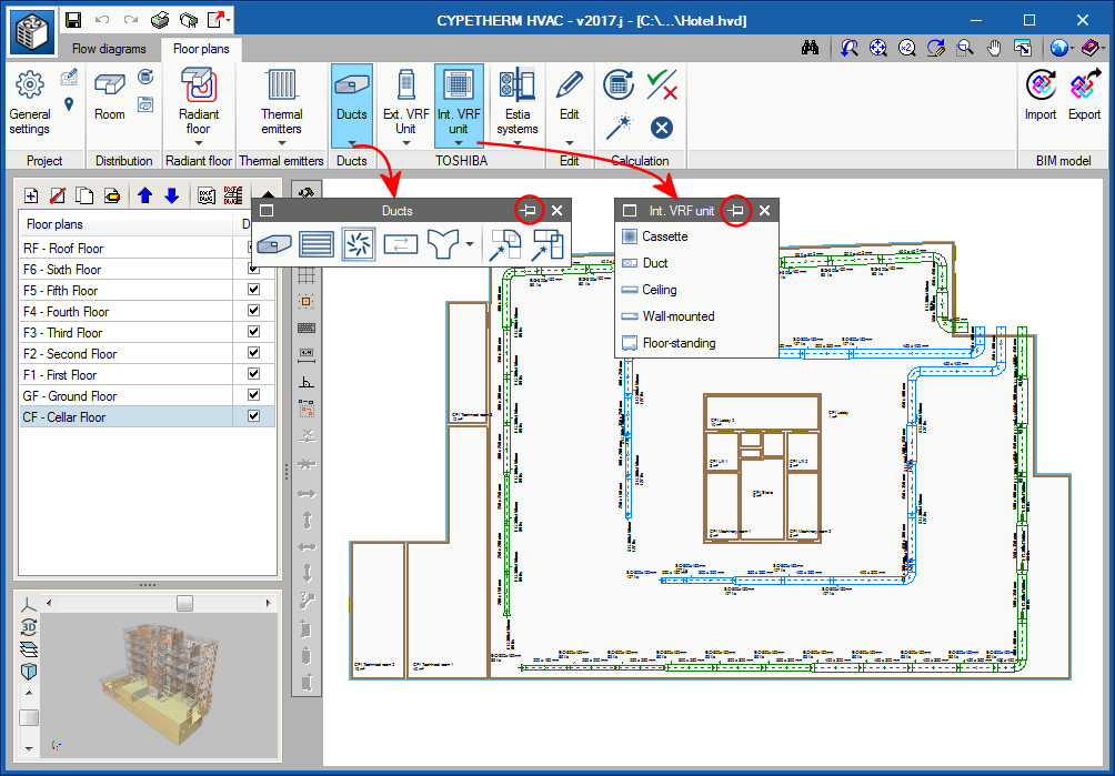
In the toolbar of some CYPE programs (e.g. in CYPETHERM HVAC and StruBIM Foundations), tools containing several options now display them in floating menus which can be placed anywhere on the screen.
These floating menus can be pinned to the screen by selecting the ![]() icon located to the right of their heading (
icon located to the right of their heading (![]() Pinned,
Pinned, ![]() not pinned), so that they do not disappear when another tool group is activated or when users access the program again.
not pinned), so that they do not disappear when another tool group is activated or when users access the program again.
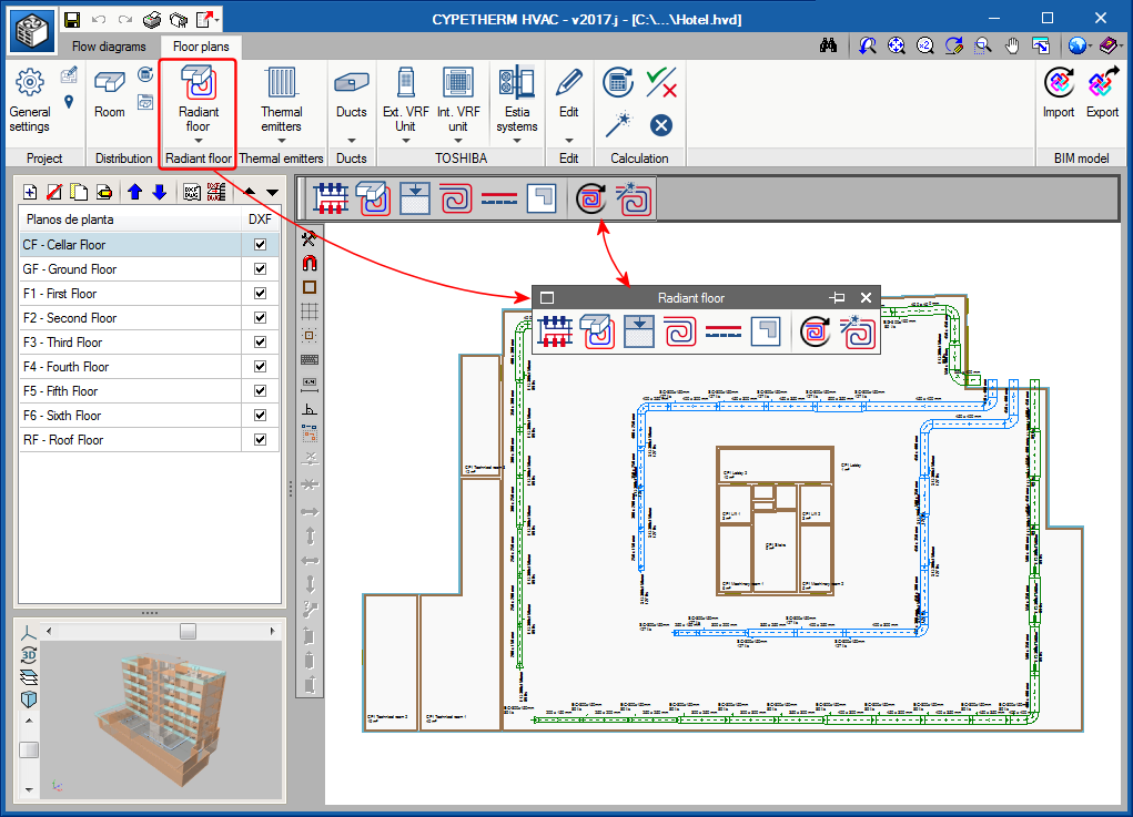
Furthermore, the floating menus can have three different tool views which alternate upon pressing the ![]() icon located to the left of their heading:
icon located to the left of their heading:
- Horizontal with large icons
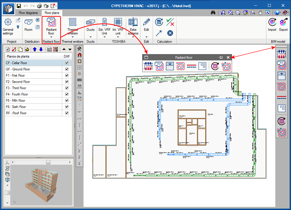
- Vertical with large icons
- Vertical with small icons and descriptive texts of the tools.
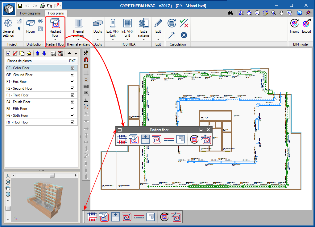
The floating menus can be adhered to the sides of the work area to look like toolbars.
All these possibilities allow users to personalise the distribution of the tools to quickly access those which are used more often.
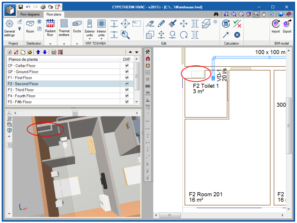
When an IFC model is imported, users can view, as well as spaces, the boundaries of the building at the floor below. In other words, on a floor with forms, a fine line will also be displayed which represents the non-accessible terrace corresponding to the roof of the floor below and the shafts reaching it.
In previous versions, users had to define a fictitious space for each shaft to be able to view them.
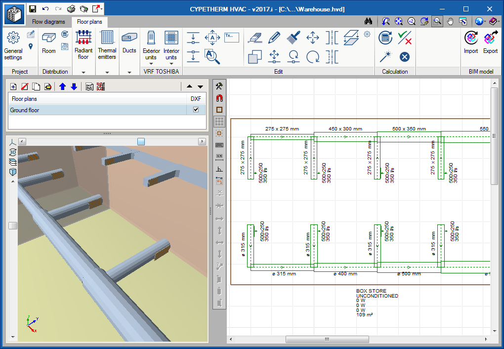
Straight ducts can be introduced continuously, i.e. when the final point of a duct span is introduced, that becomes the initial point of the next span. To stop introducing straight spans, press the right mouse button. This way, the number of mouse clicks required to introduce the duct spans is reduced.
Report for Polytherm systems
As of previous versions, CYPETHERM HVAC generates a report containing all the required information to design radiant floors. As of the 2017.i version, if the radiant floor installation includes an element of the manufacturer: POLYTHERM, an additional report is included displaying all the information of the radiant floor with all the elements of the installation.
This report has been developed in collaboration with POLYTHERM. The report details, amongst other results, the spaces of the project, the circuits that have been installed in them, the design results per manifold, the spaced with insufficient thermal power and details of the power provided by service areas.
Calculation of the cooling contribution and the cooling discharge temperatures of radiant floors
The calculation of the cooling contribution of radiant floors has been modified. With the 2017.i version, the cooling contribution is calculated based on the flow values established by the heating installations. Included in the automatic calculation of the discharge temperature for cooling of the manifolds, are the limiting values determined by the dew temperature calculated at space level or location level depending on whether dehumidification systems have been found to exist in the spaces or not. The presence of these systems is indicated in the general options for radiant floors.
Automatic selection of radiant floor circuit spacing
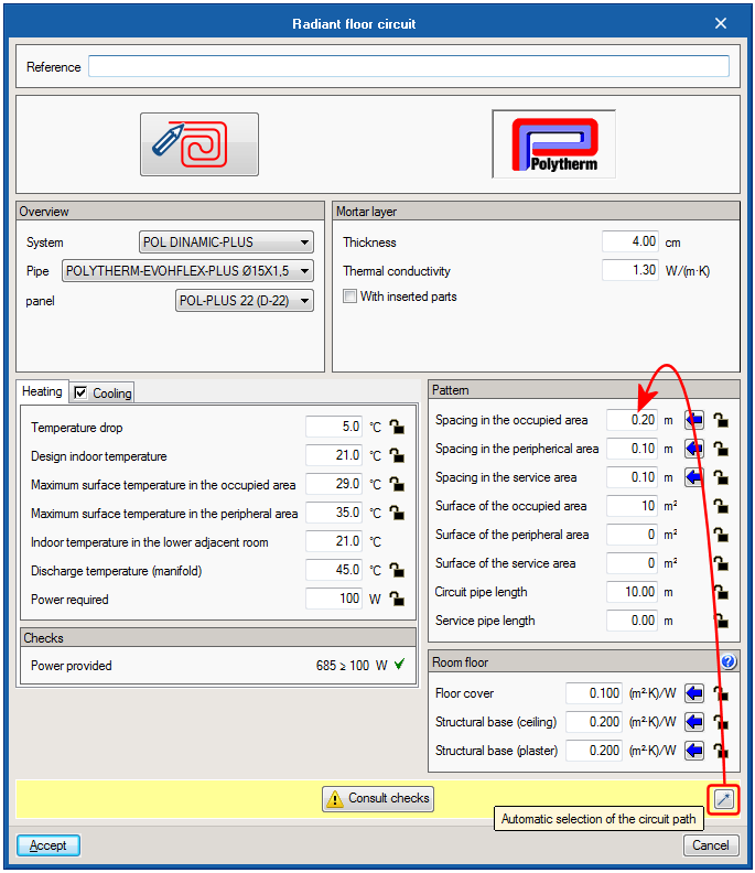
Implemented in the 2017.i version of CYPETHERM HVAC, is the automatic selection of the pipe spacing of the radiant floor circuits that have been provided. This is determined by taking into account the power requirements of each circuit and the pipe spacing available for the selected system. Additionally, the maximum pipe spacing is limited for installations with cooling contribution to avoid condensation.
As of the 2017.i version, Toshiba machines that are introduced in the circuit diagram and floor plans are linked: any modifications made to a machine in the circuit diagram will be reflected in the floor plans and vice-versa.
When a circuit diagram has been introduced, if users then go to the floor plans and access the machines’ panel to place one, those that have been introduced in the circuit diagram will first be displayed with their references.
It is also possible to proceed inversely: first the indoor machines are introduced on the floor plans, with an assigned reference. Then they are placed in the circuit diagram.
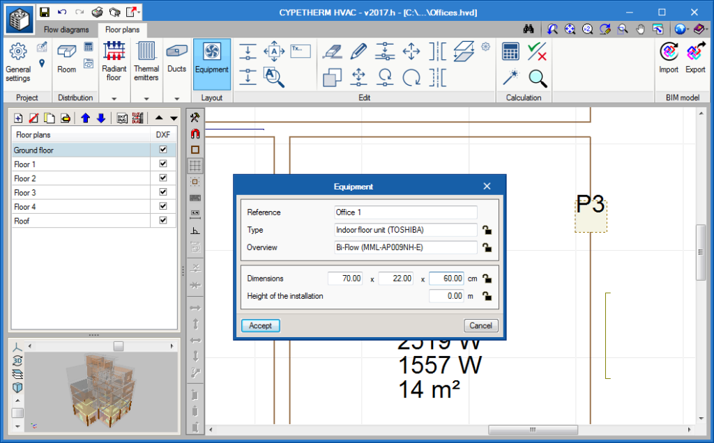
Using the “Equipment” tool, a machine can be represented on the floor plans.
For VRF equipment, if they are assigned a reference that coincides with that of a machine defined in the “Flow diagrams” tab, all the fields containing an open lock will be read and overwritten. The dimensions of all the VRF equipment are defined internally in the program.
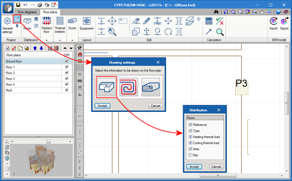
The “Drawing settings” dialogue box (“Floor plans” tab > “Project” section > “Drawing settings” button) has been rearranged. Now there are three buttons to access the drawing preferences of the elements of the installation: “Distribution”, “Radiant floor” and “Ducts”. Users can access the implemented options using the “Distribution” button. Here, the options related to the spaces in the floor plans can be activated. This way, users can choose what information can be visualised on the floor plan, such as the area, etc. The key corresponds to the name of the variable.
As occurs with all tags, it can be moved or hidden using the move tag and hide tag tools.
Circuit quantity details per roll
The required tubing rolls for the designed installation are now included in the radiant floor report, indicating the circuits making it up (including the zone to which they belong) and the length left over from each roll.
Design of the circuit paths
A new option in which the program automatically selects the best path of the circuits in occupied zones and peripheral zones, for the defined conditions, has been implemented in the editing panel of the radiant floor circuits. This option is currently only available for Polytherm manufacturer circuits.
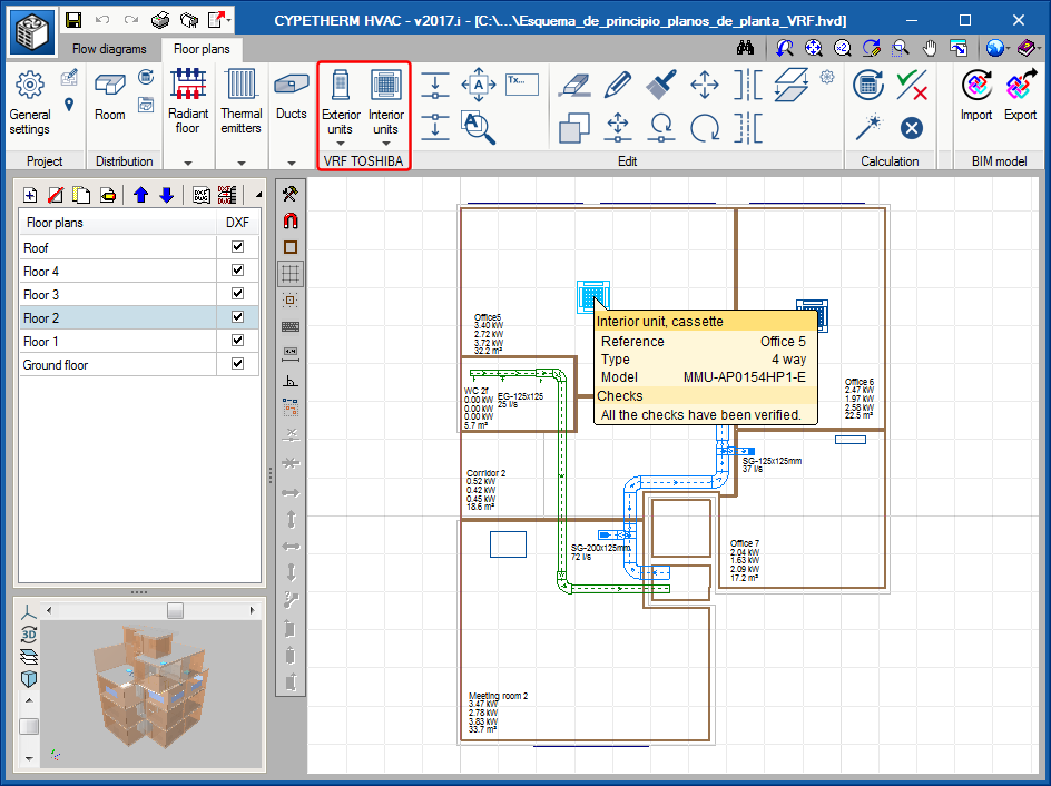
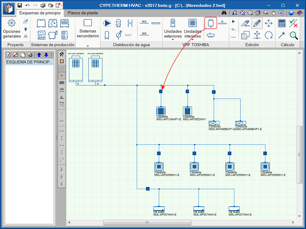
Located in the toolbar of Flow diagram tab is the Toshiba VRF systems block, which contains the elements required to introduce a variable refrigerant flow system of this manufacturer.
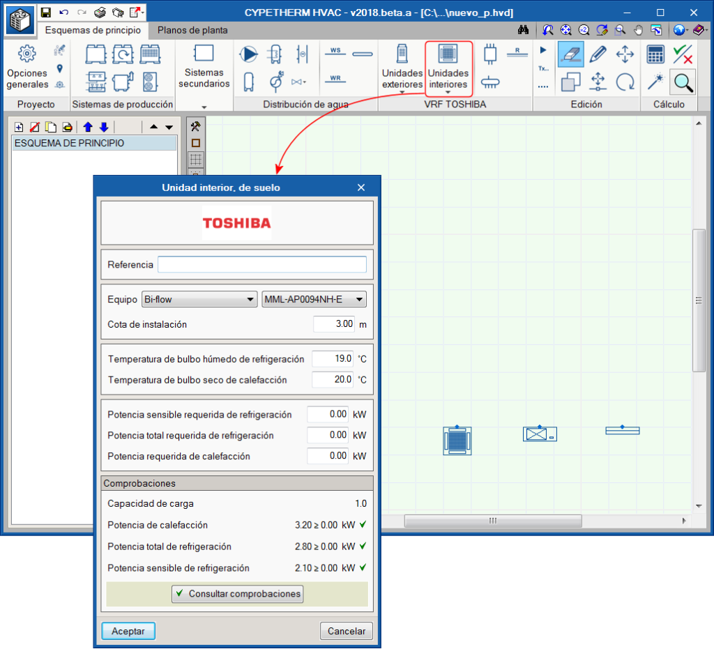
Interior units
Interior units must be located in the same space to be conditioned, and can be cassette, duct, wall, floor or ceiling-type units.
For each type of unit, there is a series of sizes with a nominal heating and cooling power. This nominal power will be corrected by the program depending on the indoor design conditions, pipe lengths and, finally, the capacity of the selected outdoor unit. The panel contains the thermal loads and the design conditions of the space to be conditioned. The program checks that the selected unit is capable of taking on those loads.
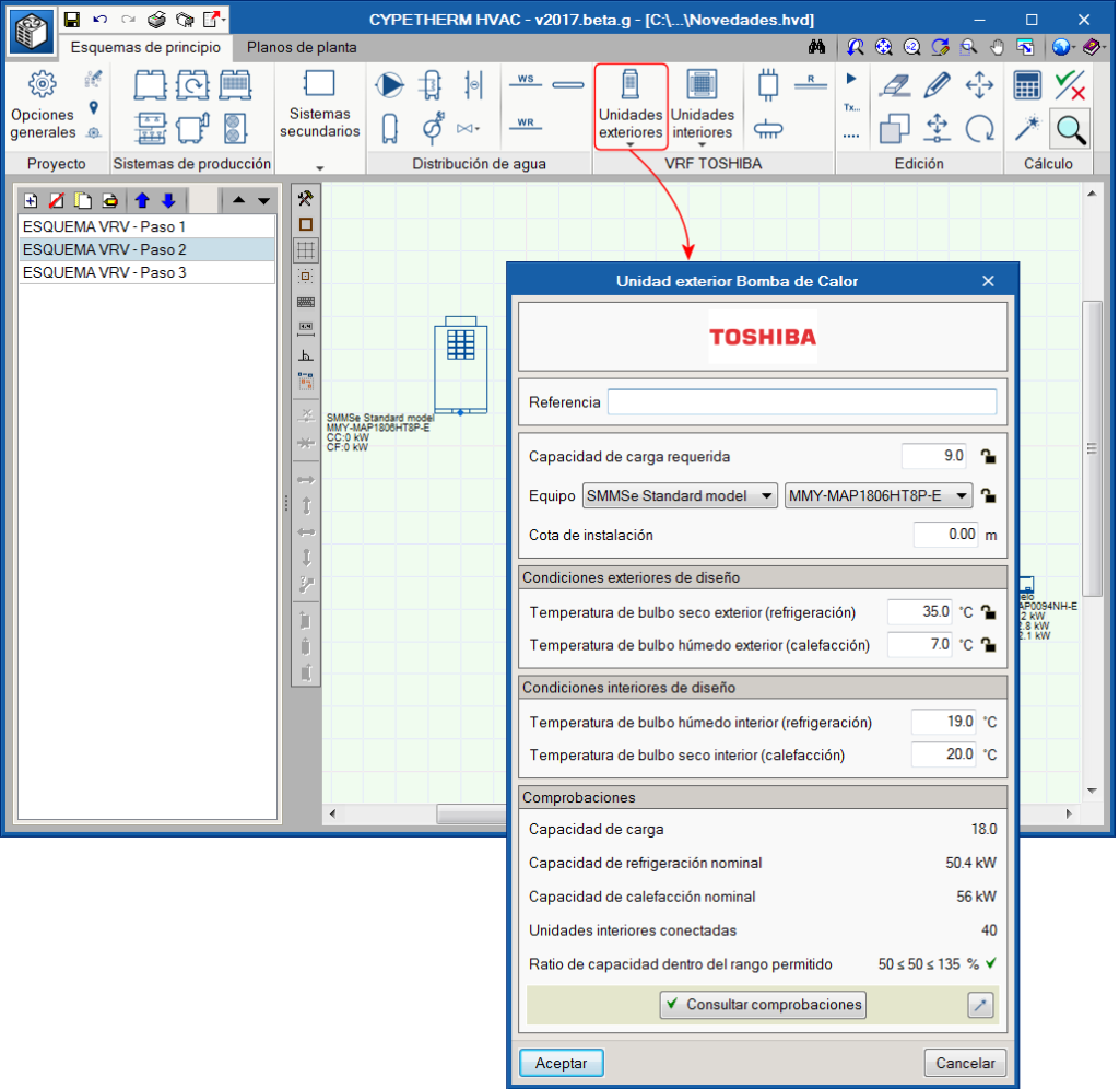
Exterior units
All the indoor unit network is connected with pipes to an outdoor machine, which can be a heat pump (2 pipes), or with heat recovery (3 pipes). That which is selected will determine the type of system.
- Exterior unit, heat pump
In this 2-pipe system, the outdoor unit will provide cold to all the indoor units at the same time, or heat to all the indoor units. - Exterior unit with heat recovery
In this type of 3-pipe system, the machine will provide cold to some indoor units and heat to other indoor units simultaneously. For this to be possible, a flow selector unit must be placed upstream of each indoor unit.
Refrigerant pipes
The pipes are drawn schematically and the program selects their diameters depending on the sum of the capacity coefficients (i.e. the thermal capacity they transport) of the units located downstream and the location of the pipe in the system.
Flow selector units
Flow selector units, also known as boxes, are devices placed in 3-pipe systems, i.e. when the exterior unit is a “with heat recovery” type unit. This device has 2 pipes on one side (which connects to the interior unit) and 3 pipes on the other. Its function is to feed the interior unit with gas or refrigerant, depending on the thermal needs at the time.
Branch circuits
Each time a main pipe splits to create a branch, it does so with a branch circuit. No icon exists for this element as the program automatically places a branch circuit and selects the required size at each branch.
Manifolds
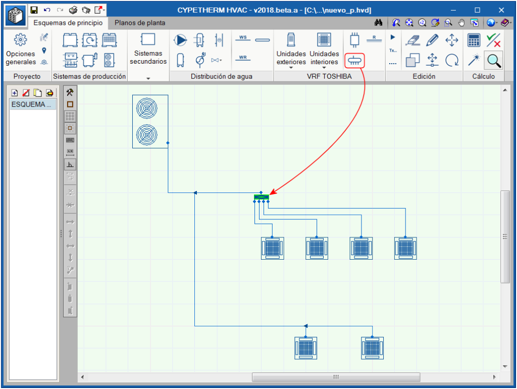
Occasionally, the main pipe has to feed several interior units located at a similar distance. For these cases, it is best to place a manifold with 4 or 8 outlets instead of having several branches that are very close in the main pipe.
Results output
Upon selecting the “Reports” button, the program generates a results report containing all the information regarding the system: element quantities, requirement checks, corrected heating and cooling capacities, circuit diagram.


