Options in the "Edit" panel in the connection editor
The "Edit" section of the top toolbar, available on the "Model" tab of the connection editor, offers the following tools:

Reference
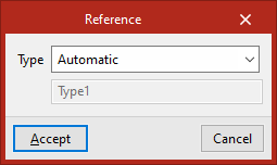
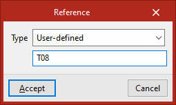
Using the "Reference" option, you can select from the "Type" drop-down menu whether the joint has an automatic reference or a user-defined reference:
- Automatic
When a reference is automatic, the prefix for that reference is defined on the "Documents" tab under the "Generation options" section, within the "Connections" tab, in the "Numbering" section.
- User-defined
In this case, the join reference is entered directly into this panel.
Modelling options
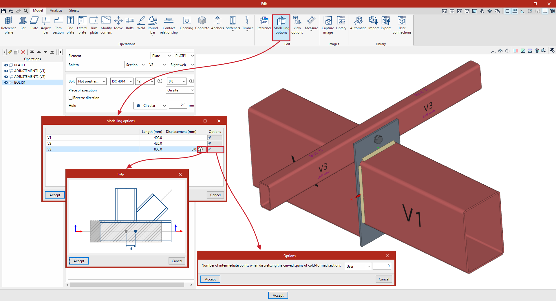
Clicking on "Modelling options" brings up a dialog box where you can enter the "Length" for each of the joint sections in the specified units. These lengths are used both in the analysis of the connection and in the 3D view of the connection.
Where applicable, it is also possible to change the "Offset" value of a profile relative to the centre of the joint. Clicking on the information button displays a help image to assist with setting this value.
In the "Options" column, for shaped sections, you can change the "Number of intermediate points when discretising curved sections of shaped profiles", which can be set to "Calculated" or a value entered by the "User".
The changes are confirmed by clicking "Accept".
Display options
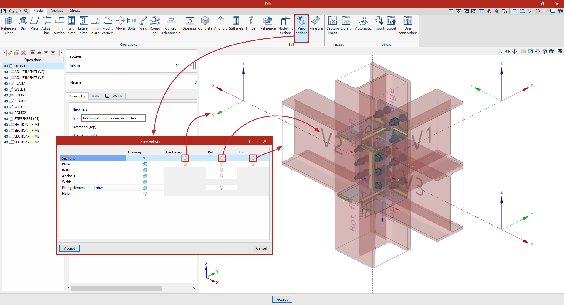
The "Display options" let you adjust how the connection model is displayed in the viewer.
After clicking on the option, in the pop-up window, the program allows you to edit the display of "Sections", "Plates", "Bolts", "Anchors", “Welds”, "Wood fasteners" and "Drill holes" individually:
- In each of them, click on the symbol in the "Drawing" column to switch the display to opaque or transparent.
- Next, clicking on the symbol in the "Axes" column displays the local axes of each element and their coordinate origin, with the X-axis shown in red, the Y-axis in green and the Z-axis in blue.
- It is also possible to enable or disable the reference text (the "Ref" column) for the join elements.
- Finally, the last column ("Env.") allows you to enable or disable the display of the envelope, which will appear in grey in the viewer. The envelope corresponds to the original geometry of each element prior to the application of adjustment or trimming operations.
Measure
The "Measure" option brings up a menu that lets you enter different measurements into the model. The available options are as follows:
- Length
Measure a distance between two points by selecting them with the left mouse button in the 3D view.
If you continue to left-click on other points, further measurements are entered. During the process, you can "Delete the last point entered" or "Delete all points entered".
The total of the measurements entered will be displayed in ochre.
To complete the measurement entry, click the right-click button.
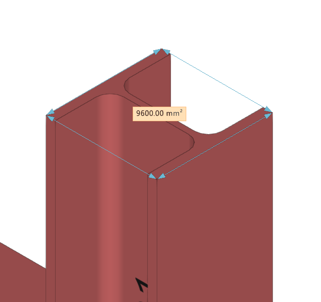
- Area
Measure the area of a closed polygon defined by the points selected using the left mouse button in the 3D view.
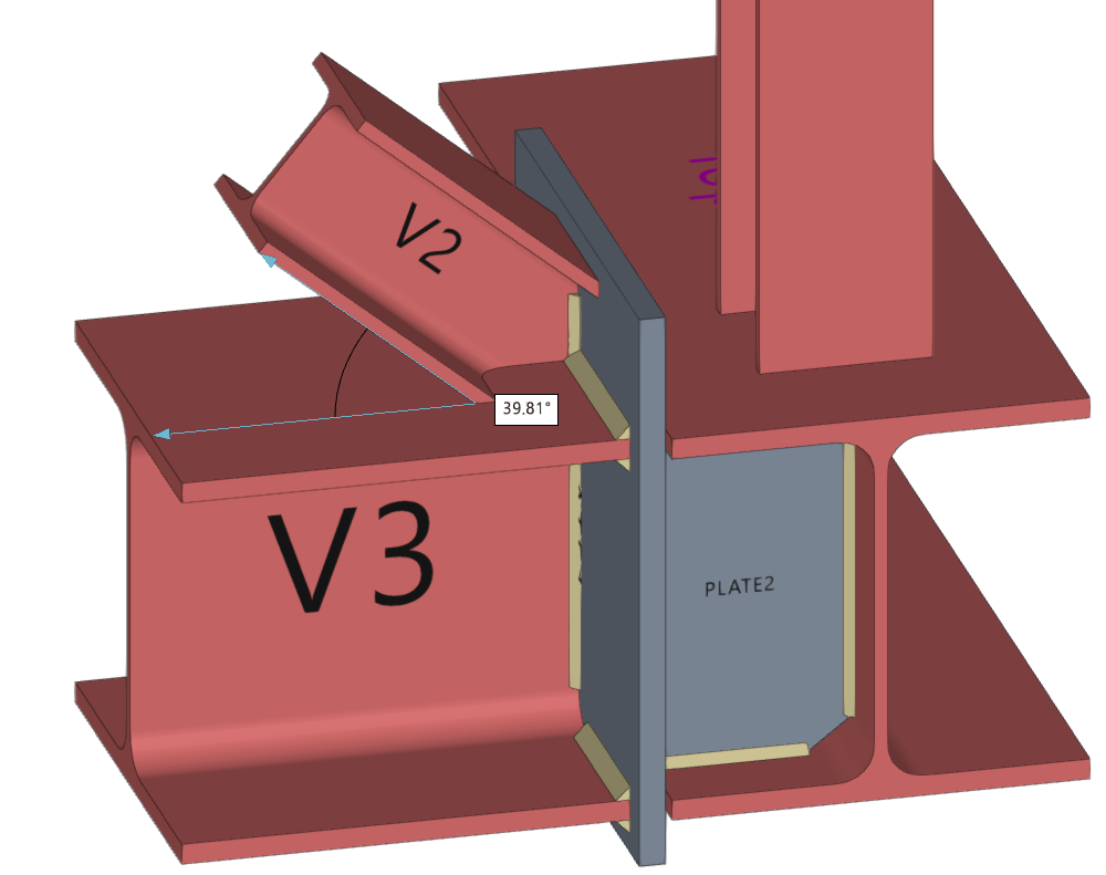
- Angle
Measure the angle defined by a vertex and two points selected using the left mouse button in the 3D view.
Whilst entering measurements, you can click the right mouse button repeatedly to delete the measurements one by one, if desired.