Managing the visibility of project elements
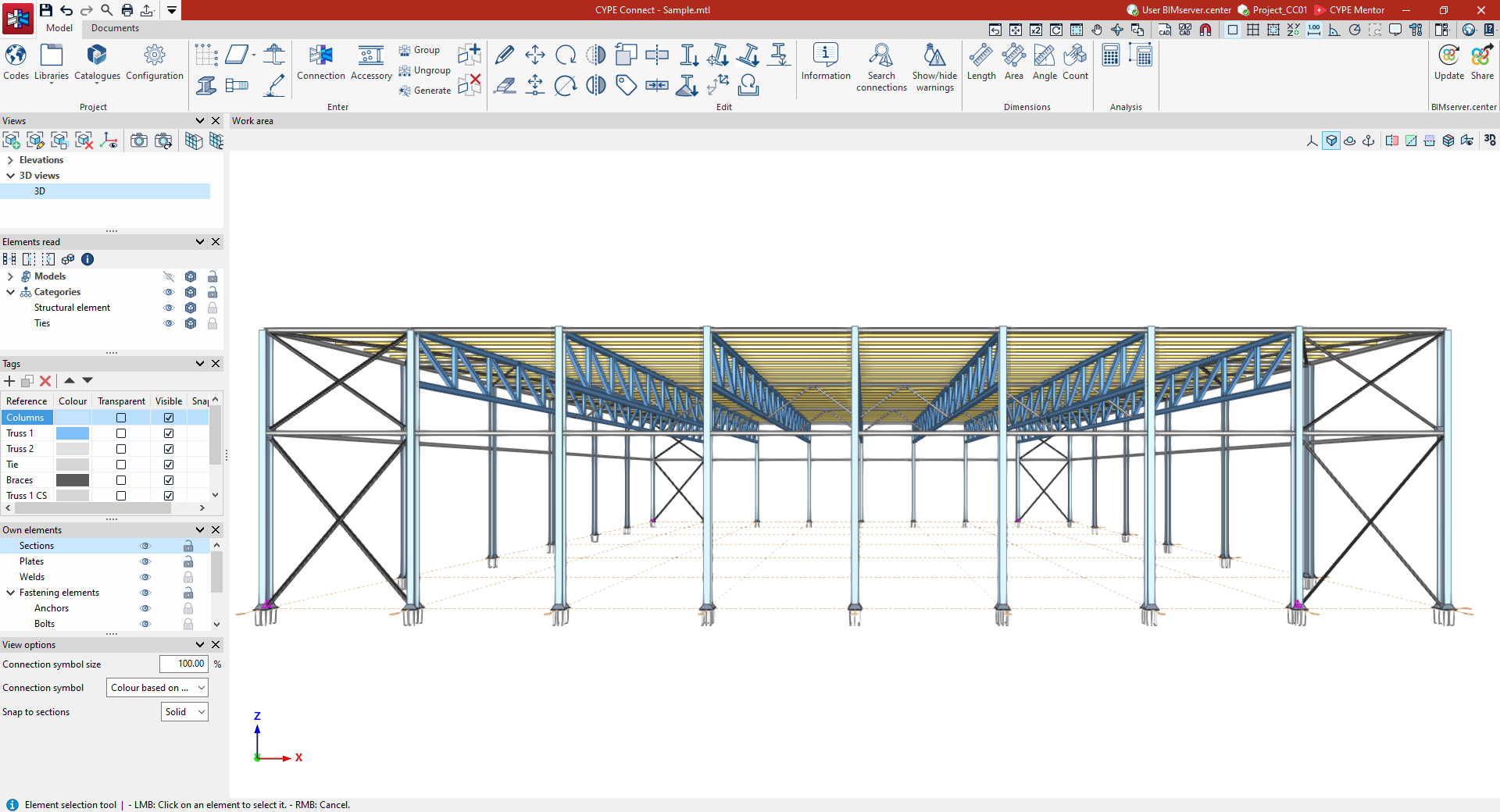
The different elements required to model the project can be viewed via the following panels located on the left-hand side of the program's main interface, which are visible in both the "Model" and "Documents" tabs:
- Views
- Elements read
- Tags
- Own elements
- View options
Managing views
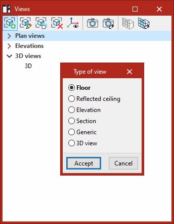
Like other CYPE 3D modelling programs, StruBIM Steel allows you to create different views to make it easier to navigate and model the structure. The following types of view can be created:
- Floor
- Reflected ceiling
- Elevation
- Section
- Generic
- 3D view
| More information: |
|---|
| The view management system is a feature common to several CYPE tools. You can find further information via the following link. |
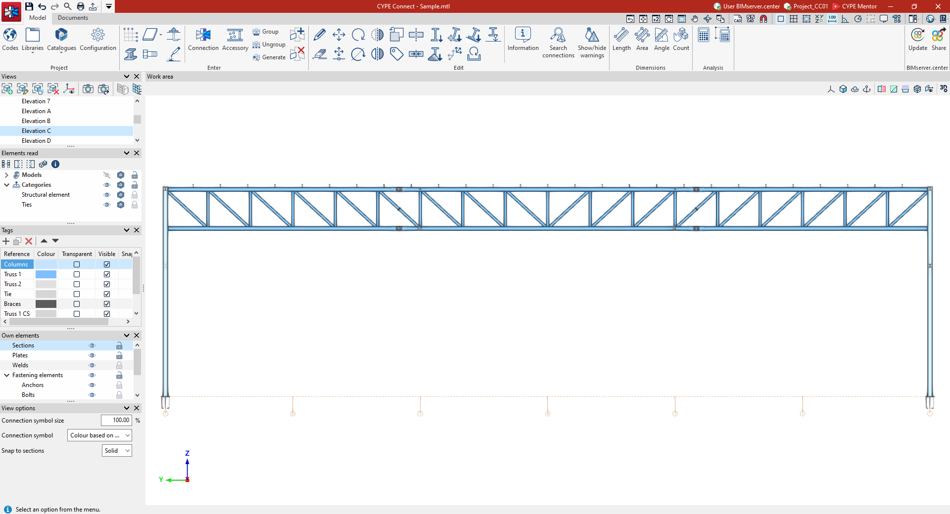
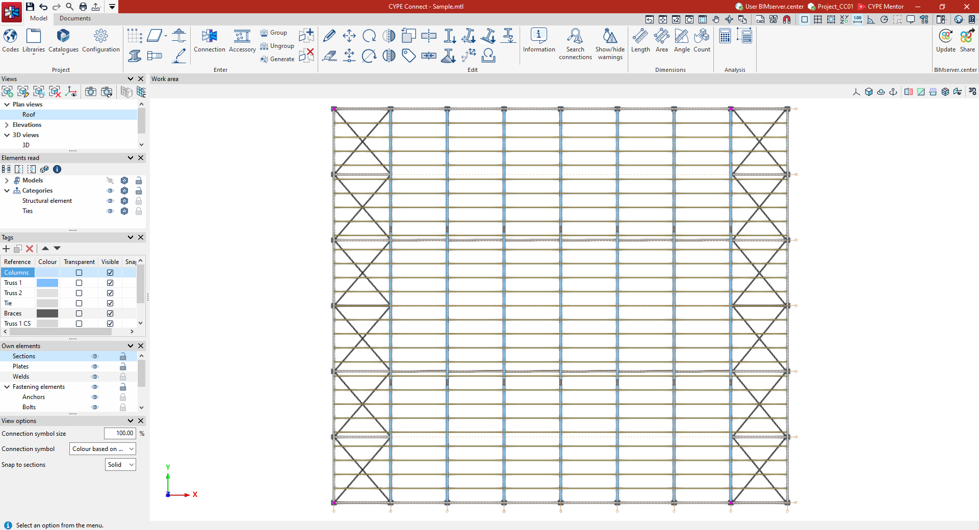
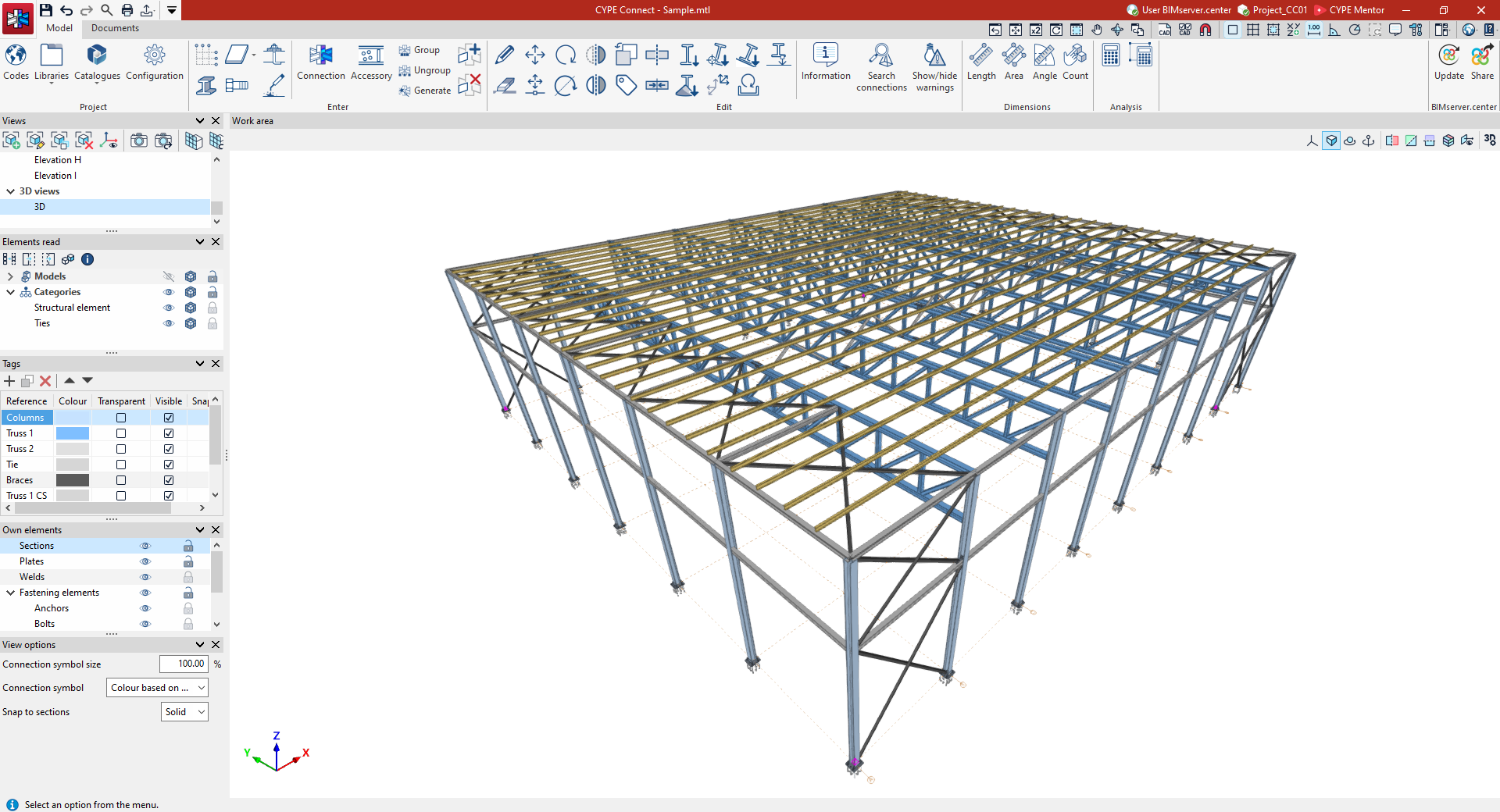
Managing elements read
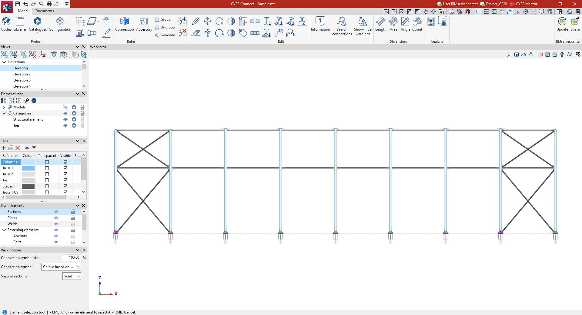
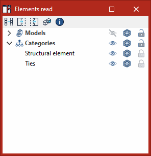
The "Elements read" panel controls the visibility of the various models that make up an Open BIM project developed on the BIMserver.center platform and imported into CYPE Connect. The elements from these external models can then be viewed and used as a reference when entering the structure itself into the program.
The options for managing the visibility of the elements read in the various columns allow you to:
- Toggle the visibility of elements in the workspace (using the "Visible" button).
- Change the "Display mode" of the elements by choosing between normal view, transparent view or wireframe view.
- Lock the "Snap" fields so that they cannot be snapped or selected during the various data entry or editing processes.
There are two ways to manage the visibility of these models:
- Using the "Models" filter, which is applied to the various imported models: architectural model, terrain model, concrete structure, etc.
- Using the "Categories" filter, which is applied to the various categories found in the imported models, in accordance with the IFC schema classification.
Managing tags
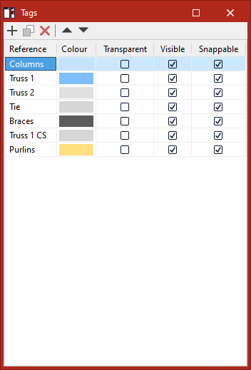
You can create "Tags" to group the different parts of the CYPE Connect model from the relevant panel on the left-hand side. For each tag created, you can:
- Define a "Reference"
- Define a "Colour" for the 3D rendering
- Enable or disable the "Transparent" view
- Indicate whether it is "Visible" or not
- Indicate whether it is "Snappable" or not
The "Assign tags" option, within the "Edit" section of the top toolbar, can be used to assign model elements to the tags you have created or to remove their assignment.
Managing own elements
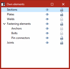
The visibility and snapping of elements modelled in CYPE Connect can be controlled from the "Own elements" panel on the left-hand side of the app.
Each of the following categories can be set to "Visible" or hidden, and "Snappable" or not, using the buttons in the relevant columns:
- Sections
- Plates
- Welds
- Fastening elements
- Anchors
- Bolts
- Pin connectors
- Joints
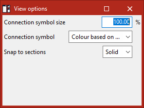
View options
In the "View options" section at the bottom left, you can control the following settings:
- Connection symbol size
This value must be between 1 and 1000 per cent (default: 100 per cent). - Connection symbol
You can choose the colour of the connection symbols:- Colour based on the tag
- Colour based on check status
- Snap to sections
You can adjust how the sections are snapped:- Axis
Sections are snapped along their axis. - Solid
Sections are snapped by selecting any of the solid surfaces.
- Axis