Generating and laying out solar thermal energy system diagrams
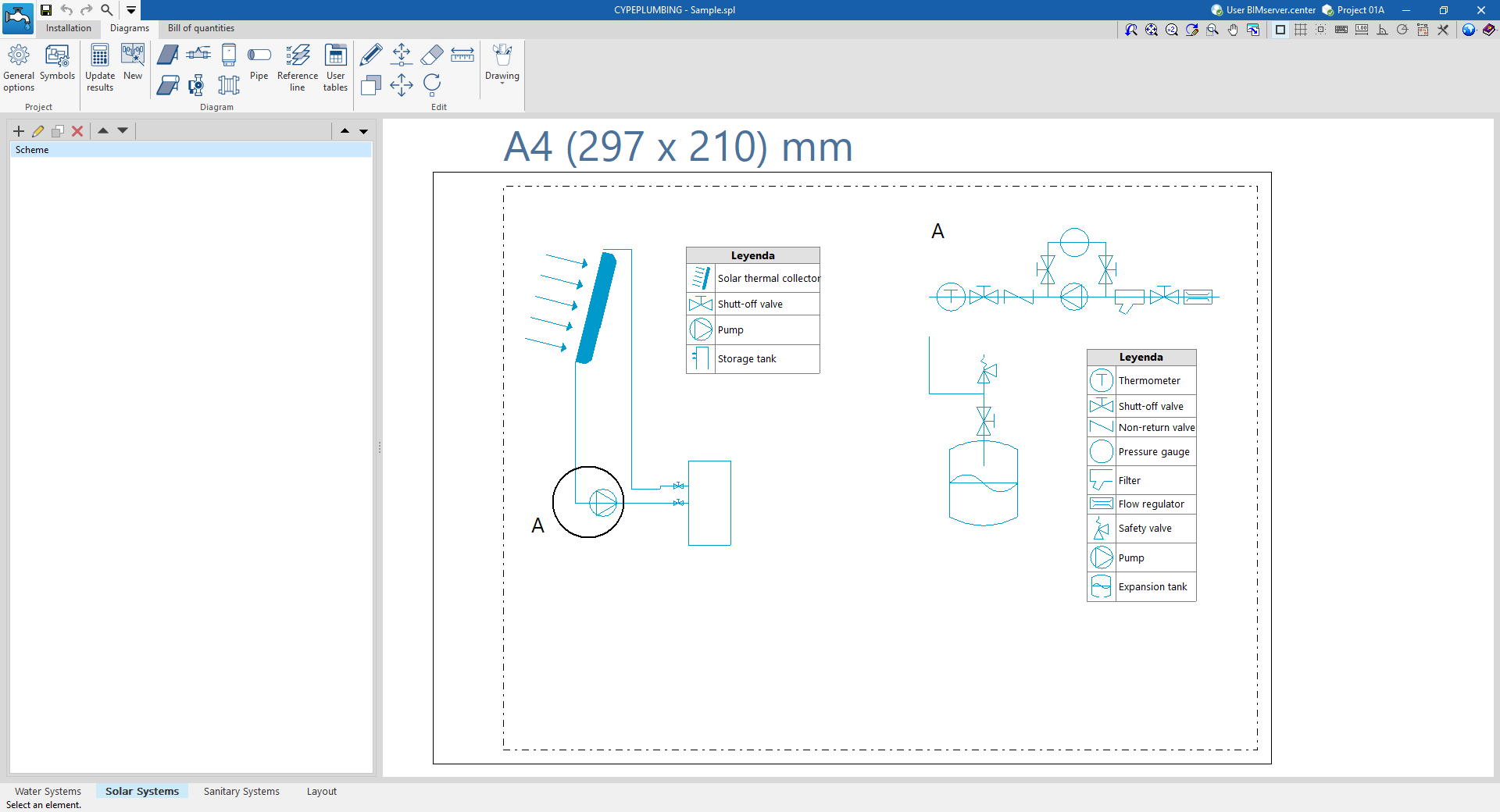
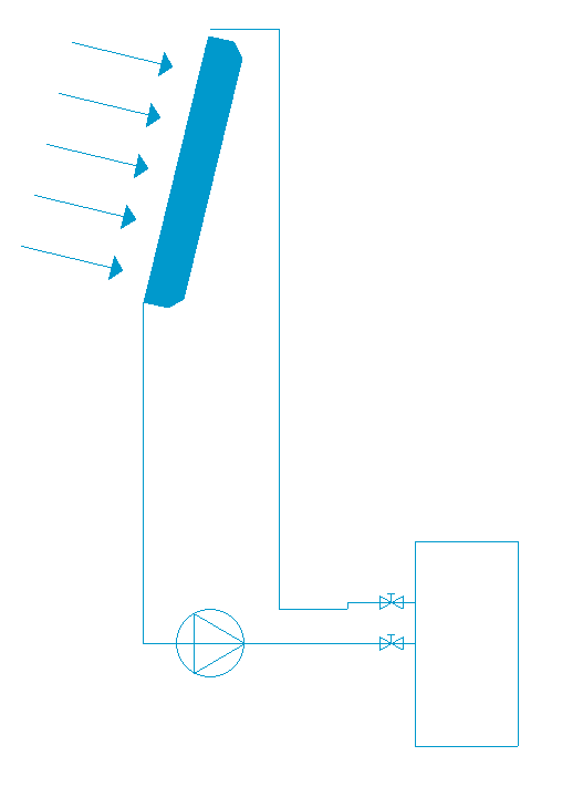
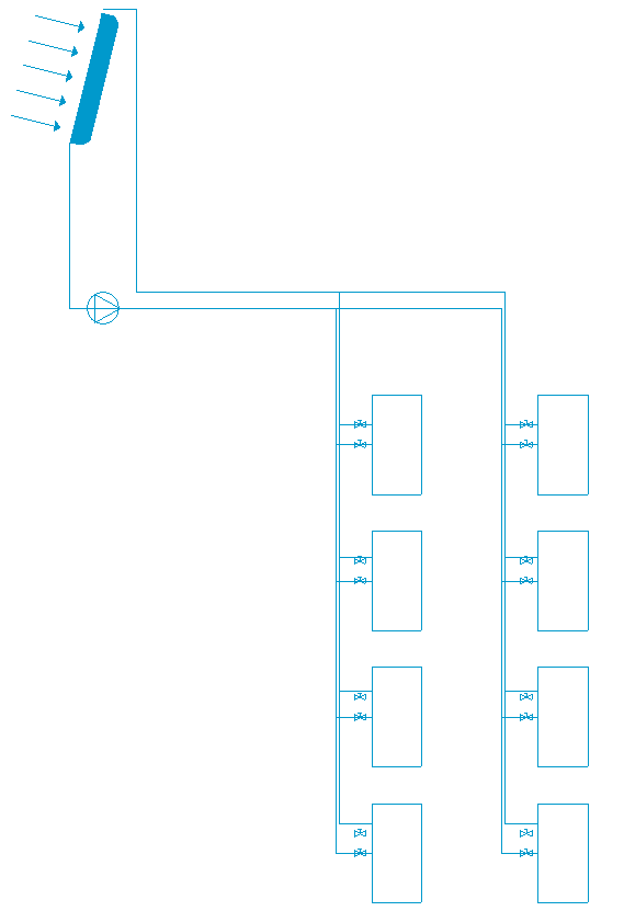
The "Diagram" tab, available at the top of the "Solar Systems" tab, allows users to automatically generate the diagrams of the solar thermal system from the model information developed in the "Installation" tab, or to create them manually using the available drawing tools:
- To create the diagrams from scratch, the necessary format sheets are first created using the options on the left-hand side. Then, the schematic elements are entered in the work area on the right-hand side using the options in the top toolbar.
- To generate the layouts automatically, the "New" option at the top is used. It is then possible to modify the generated diagrams in the work area using the options in the top toolbar.
Composite drawings can be selected in this tab to be printed together with the rest of the drawings of the job using the corresponding options.
Diagram management
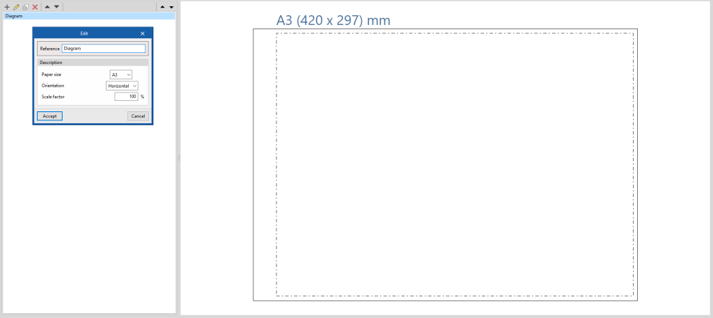
The diagrams of the solar thermal energy system are made up on sheets of different formats. The tools for creating and managing diagrams are located on the left-hand side of the interface.
The following features can be configured when creating or editing a diagram:
- Reference
- Description
- Paper format
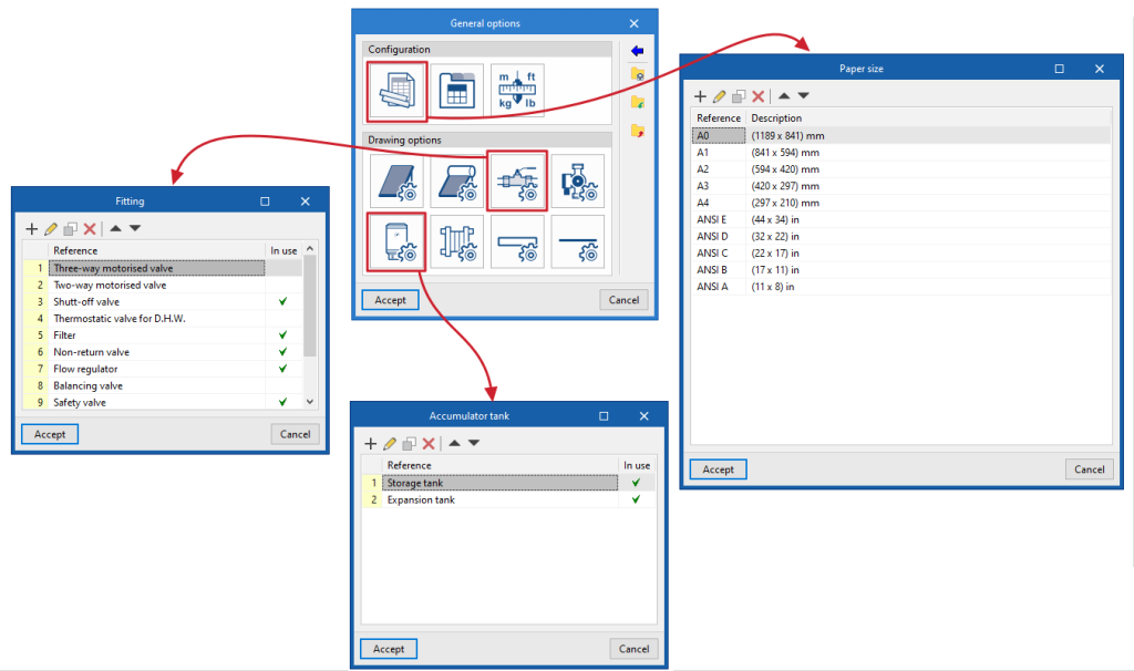
The available paper formats can be configured in ‘General Options’. - Orientation (Landscape / Portrait)
- Scale factor (%)
Options in the "Project" group
In the "Project" group of the top toolbar, the program offers the following utilities:
General options
This configures the available paper formats and table types, the units of measurement, and the graphic representation of the elements of the solar thermal energy system diagrams, defining their colour and symbols.
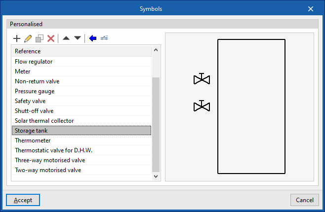
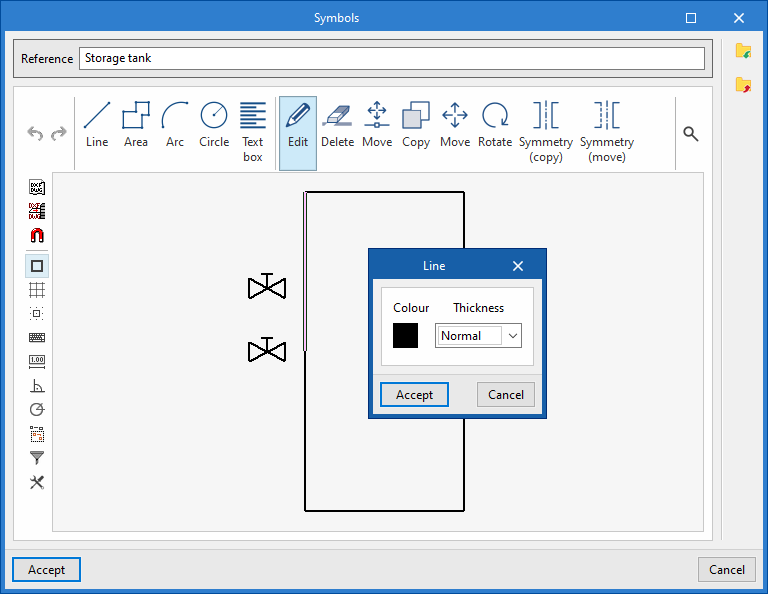
Symbols
Used to create and edit the symbols of the system elements by means of a drawing editor. The symbols contained in DXF, DWG or DWF files saved on disk can be imported. These symbols can be selected in the configuration defined for each element under "General options
Options in the "Diagram" group
In the "Diagram" group of the top toolbar, the program offers the following options:
Update results
Updates the information available for generating new diagrams with the results of the analysis.
New
Automatically generates the diagram of the solar thermal system if the model contains the appropriate information.
The diagrams generated can be further modified using the tools available at the top.
Tools for entering diagram elements
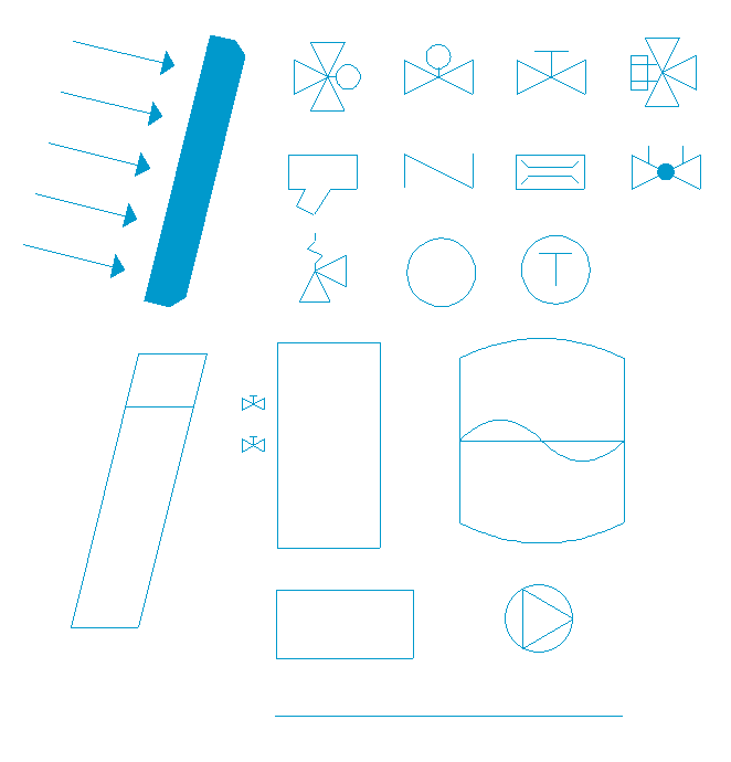
These options allow users to freely enter these elements in the diagram of the solar thermal system:
- Solar thermal collector
- Solar thermal collector with accumulator tank
- Fitting
- Pump
- Storage tank
- Heat exchanger
- Pipe
In each of them, the following parameters are defined:
- Reference
Reference of the particular element. - Drawing options
Selects the symbol previously defined in the "Drawing options" of the "General options".
Reference line
Enters a reference line. These lines can be used to indicate the layout of the diagram elements on the different floors of the building.
User tables
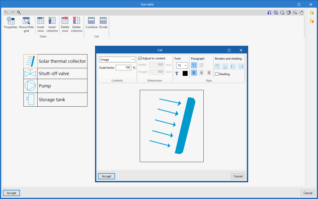
Inserts legends or tables with complementary information in the diagrams.
When a table is created, it can be "Generic", for which the number of rows and tables is specified and the content of its cells is filled in a free editor, or "Key" type, in which case it can be "Automatically generated" according to the elements arranged in the diagram.
Table types can also be managed via the corresponding option in the "General options".
Editing tools
The options in this menu are used to perform the following operations to edit the elements of the system diagram:
| Edit | Edits the parametric properties of the selected element in the model. | |
| Copy | Creates a copy of one or more elements. | |
| Move element | Moves an element or a node of an element. | |
| Move a group of elements | Moves a group of elements. | |
| Delete | Deletes a previously entered element. | |
| Rotate | Rotates an element. | |
| Measure lengths on plan | Measures lengths and angles between points defined in the model. If a closed outline is selected, it also indicates the area. |
Drawing tools
The options in this menu are used to enter the following drawing resources:
| Elevation | Enters an elevation between two selected points, indicating the line colour, line thickness, and text size. | |
| Line | Inserts a line between two selected points, indicating its colour and thickness. | |
| Text | Enters a text and a reference line, indicating its colour, the line thickness and the text size. | |
| Text box | Enter a left-aligned, right-aligned or centred text box, indicating the colour and size of the text, the properties of the frame and the background fill. | |
| Arc | Enter an arc and, optionally, its radius, indicating the line colour, line thickness and text size. | |
| Circle | Enter a circle and, optionally, its radius or diameter, indicating the line colour, line thickness, and text size. | |
| Rectangle | Enter a rectangle and, optionally, its area, indicating the line colour, line thickness and text size. | |
| Area | Enter a dotted polygon and, optionally, its area, indicating the line colour, line thickness, and text size. | |
| Polyline | Inserts a polyline by points, indicating its colour and thickness. | |
| Edit | Edit the properties of the selected drawing resource. | |
| Delete | Deletes the selected drawing resources. | |
| Move | Moves the selected drawing resource or parts of it. | |
| Assign | Assigns the properties of a drawing resource to others. When selecting a drawing resource, resources with the same properties are highlighted in orange. |

