Inserting pipes into the water supply system
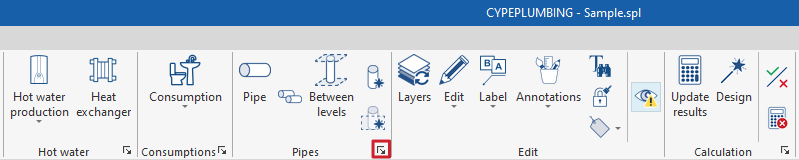
Within the "Installation" tab of the "Water Systems" tab, in the "Pipes" group of the main toolbar, there are options for entering the pipes of the water supply system:

Pipe
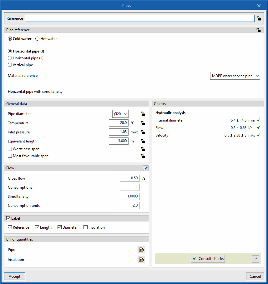
Allows pipes to be inserted into the water supply system in any position.
When inserting or editing a pipe, the following parameters can be configured. Some parameters only appear if the "Simplified entry" option, accessed from "Design options" under "General options", is deactivated:
- Reference
Element reference. This value can be locked or unlocked. If unlocked, the program will create or modify the reference when updating results. - Pipe reference
Allows the pipe type to be selected by its reference and depending on whether it is a "Cold water", "Hot water", "Hot water return", "Auxiliary supply" or "Auxiliary return" pipe. These types can be created and edited from the "Project" group, in the "Design and check options to be carried out" section of the "General options". The program also provides information on the "Material reference". The pipe reference can be locked or unlocked. If it is unlocked, the program can modify the pipe reference when updating results according to their arrangement in the model. - General data
Defines the element's general data. Some of these values can be locked or unlocked. If a value is locked, it is not modified when updating the results and remains unchanged.- Pipe diameter (Lock/Unlock)
Allows the pipe diameter to be selected from those available in the series. The materials and equipment in the system can be created and edited from "Material and equipment selection", in the "General options" of the "Project" group. - Temperature (Lock/Unlock)
- Inlet pressure (Lock/Unlock)
Defines the inlet pressure in the pipe. - Equivalent length (Lock/Unlock)
- Worse case span (optional) (Lock/Unlock)
- Most favourable span (optional) (Lock/Unlock)
- Pipe diameter (Lock/Unlock)
- Flow
Used to define the flow rate of the pipe. In the dialogue box accessible from the button on the right-hand side, the "Cold water flow rate" or "Hot water flow rate" values that will affect the upstream section that will feed the pipe being edited or entered can be specified. The values shown in the main pipe editing panel correspond to those of the pipe being edited or entered are as follows:- Gross flow
- Consumptions
- Simultaneity
- 3D layout
Used to check or edit the coordinates of the points of the polygonal line that defines the position of the pipe in the model. This section only appears when editing a previously entered pipe.- X, Y, Z
- Label (optional)
Manages the information visible in the element's label.- Reference
- Length
- Diameter
- Insulation
- Bill of quantities
Controls the generation of the element's bill of quantities using filters.- Pipe
- Insulation
- Consult checks
Used to consult and list the checks carried out on the element. These checks can be activated, edited or deactivated from "Design and check options to be carried out", in the "General options" of the "Project" group. - Design
This tool, available from the button in the bottom right corner of the pipe editing panel, allows the pipe to be automatically designed to meet the defined checks.
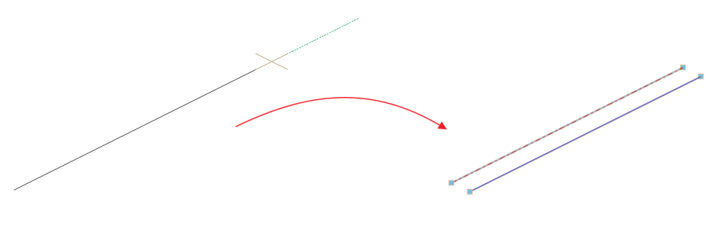
Multiple pipes
This option allows multiple or parallel pipes to be inserted into the water supply system in any position.
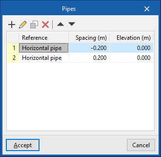
By clicking on this option, the program can define the characteristics and relative layout of one or more pipes by adding entries in the table. The following parameters must be entered:
- Reference
Reference of each pipe. - Spacing
Spacing of each pipe with respect to the insertion line in the model. - Elevation
The elevation of each pipe with respect to the insertion line in the model.
After being inserted, the model, geometry and properties of each of the pipes inserted using this option can be edited like any other pipe, without maintaining a link with the other pipes inserted at the same time.
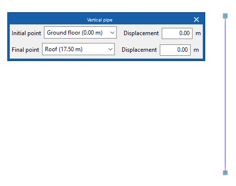
Pipes between levels
The "Between levels" option is used to insert water supply pipes between levels.
When clicking on this option, the program can define the pipe properties by means of an editing panel identical to the one that appears when using the "Pipe" option.
Then, in the "Properties - Vertical pipe" dialogue box, the level associated with the "Final point" of the pipe is defined, together with a "Displacement" above the indicated level, expressed in positive or negative values.
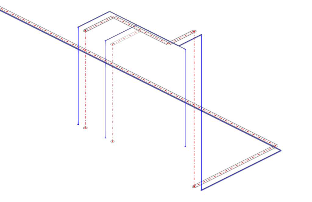
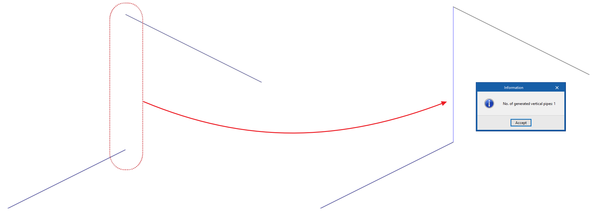
Generating vertical pipes
The program offers two tools for the automatic generation of vertical pipes connecting other elements (e.g. pipes or consumptions) previously arranged in the model.
- The first option generates the vertical pipes at all points of the job where possible.
- The second option generates the vertical pipes between the elements selected by the user, if possible.
After using any of these tools, the program reports the number of generated vertical pipes. From here, users can edit or delete the pipes created in the process if they wish to do so.
Esta herramienta solamente genera una tubería vertical entre dos elementos This tool only generates a vertical pipe between two elements located at different heights if their ends, or if the points where the vertical connection pipe is to be placed, have the same coordinates on the plan.
| Note: |
|---|
| The "Pipes" option in the bottom right-hand corner of the group can be used to access the options for defining the elements in this group. These options are the same as those available in the "Design and check options to be carried out" section, in the "General options" of the "Project" group. |