Architectural modelling in the "3D model" tab
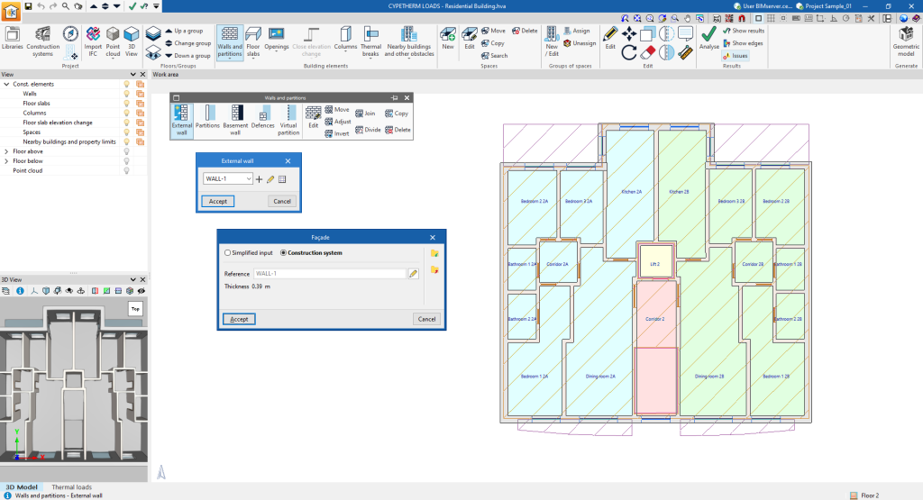
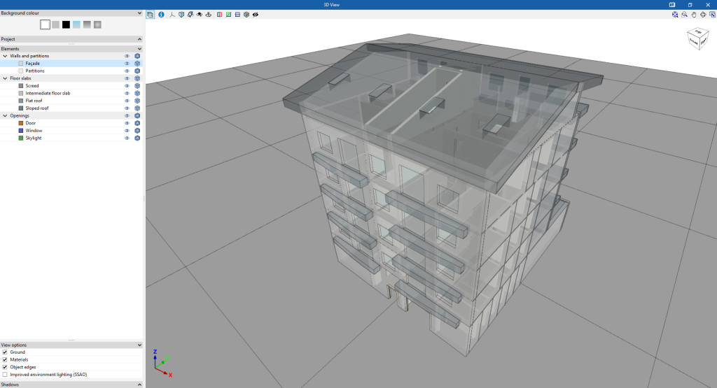
The building geometry can be defined directly in the program using the tools in the "3D model" tab at the bottom of the program's general interface.
This tab is used to configure the project and the floors or groups, to enter the building elements (walls and partitions, floor slabs, openings, etc.) and the spaces, and to define the groups of spaces of the building from scratch, together with nearby buildings and other obstacles, in a work environment identical to that of the independent program IFC Builder.
Here, together with the architectural geometry, it is also possible to define the construction systems associated with the different typologies of the elements entered.
Additionally, in this tab, IFC files can be imported by means of a specific wizard that automatically generates the elements of the 3D model.
More information on the options and features of this environment can be found on the IFC Builder detailed information page.
Generating the thermal model from the 3D model
Once the 3D model has been completed, the "Geometric model" option in the "Generate" group from the top toolbar can be used to generate the thermal model of the building and move to the tab of the same name in the "Thermal loads" tab, which allows work to continue.

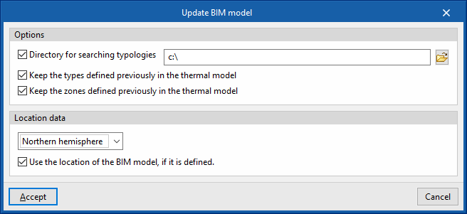
Using this option opens the "Update BIM model" window, with the following options:
- Options
- Directory for searching typologies (optional)
- Keep the types defined previously in the thermal model (optional)
- Keep the zones defined previously in the thermal model (optional)
- Location data
- Northern hemisphere / Southern hemisphere
Selects the hemisphere where the project is located. - Use the location of the BIM model, if it is defined (optional)
Completes the generation of shadows on the elements of the job by collecting the information of the elements of the site (such as nearby buildings or nearby obstacles) that are defined in the BIM model.
- Northern hemisphere / Southern hemisphere


