Work environment
The Open BIM Switchboard interface is divided into three tabs with different work environments: "Switchboards", "Assembly" and "3D layout":
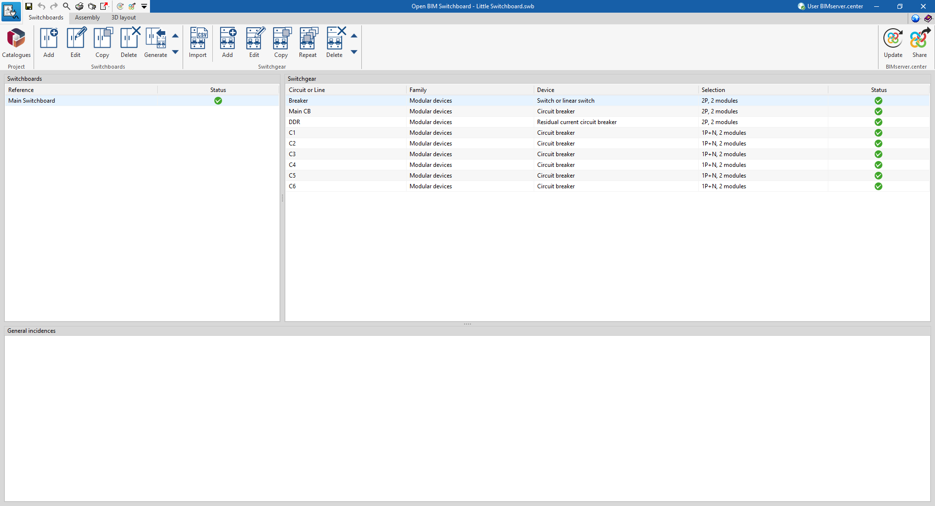
"Switchboards" tab
The "Switchboards" tab has a work environment that allows you to define the electrical switchboards of the system included in the file and their associated switchgear.
This tab displays the following:
- An upper toolbar containing the tools for: defining the catalogues and importing the electrical system project; entering, editing or generating the electrical panels; and importing, entering or editing the switchgear associated with each panel.
- On the left, a panel showing a report with each of the defined panels.
- On the right, a list of devices describing the switchgear associated with the switchboard selected on the left.
- At the bottom, a display of the general incidents detected by the program.
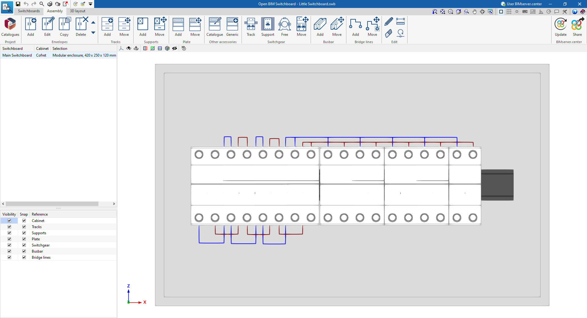
"Assembly" tab
The "Assembly" tab has a work environment that allows you to detail the enclosure data of each of the switchboards (defined in the "Switchboards" tab) and to arrange elements such as rails, supports, plates, switchgear, busbars and bridge lines inside the switchboards.
This tab displays the following:
- An upper toolbar containing the tools for: defining project catalogues; entering or editing enclosures; defining tracks, supports, plates and other fittings; arranging the switchgear in the switchboard; adding or moving busbars; entering bridge lines. The editing tools are also located here.
- On the left-hand side, a panel showing a list of boxes, indicating the switchboard to which each one is associated, as well as a tool for managing the visibility and snapping of the elements arranged in the work area, sorted by category.
- On the right, the work area, where the box selected in the list on the left-hand side is displayed and detailed.
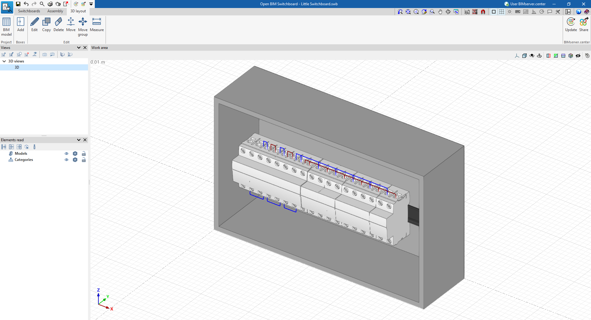
"3D layout" tab
The "3D layout" tab has a work environment that allows the boxes defined in the previous tabs to be placed in the space.
This tab displays the following:
- An upper toolbar where the tools for displaying the elements arranged in the model and the tools for adding the boxes in the work area are located. The editing tools are also located here.
- The work area, on the right of the screen, where the boxes associated with the electrical panels are entered and displayed in the space.
- On the left-hand side, several panels with tools for defining the project views and managing the visibility of the elements read from the BIM model.