Options for entering elements on the "Workspace"
The option bar for entering elements is located at the top left of the "Work area" window and appears when entering or editing an element in the model. This bar has the following options, which depend on the active view and the element(s) being entered or edited:

- Force elevation (optional)
Defines the position of the new element in the model.- If this option is active:
- If a component of the model is snapped, its position will be projected onto the work plane of the view selected in the drop-down menu, where the new element will be inserted, adjusted with the "Displacement" indicated on the right.
- If no component is snapped, the new element will be inserted at the cursor position and on the working plane of the view selected in the drop-down menu, adjusted with the "Displacement" indicated on the right.
- If this option is left deactivated:
- If a component of the model is snapped, the new element will be inserted at the exact position of that component, even if it is outside the working plane of the selected view.
- If no component is snapped in, the new element will be inserted at the cursor position and on the work plane of the selected view in the "Views" panel.
- If this option is active:
- Select views (drop down)
This drop-down menu is used to select one of the views created in the "Views" panel to support the operation of the "Force elevation" option:- In 2D views such as elevations, sections or plans, the selector is locked to the view selected in the "Views" panel; this means that no other view can be selected.
- In 3D views, any of the views created in the "Views" panel can be selected.
Note:
The "Views" panel is located by default on the left-hand side of the program's general interface and allows users to create and maintain 2D and 3D views of the model. Each of these views has an associated "work plane", which can be defined using the top options of the "Views" panel mentioned above.
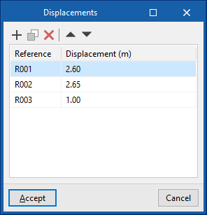
- Displacement (optional)
Used to enter a displacement value, either positive or negative, which will be applied to the position of the working plane of the view selected in the drop-down menu above. The option to the right of this field is used to save and load displacements for the entire job, indicating their reference and value.
- Points
This section is activated when inserting points in the workspace to define the geometry of a new element and has the following options:- Erase the last entered point
- Erase all entered points
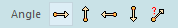
- Angle
Used to indicate the insertion angle of the new element in the "Work area" with respect to the display on the screen by means of the following options:- 0º
- 90º
- 180º
- 270º
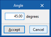
- Editable angle