Introduction
CYPEFIRE is a program created to assist professionals during the building design process and is used to check compliance with fire safety regulations.
This tool allows users to define both passive protection systems (compartmentalisation, evacuation, outdoor propagation, etc.) and active protection systems (extinguishers, detectors, etc.).
Workflows supported by the program
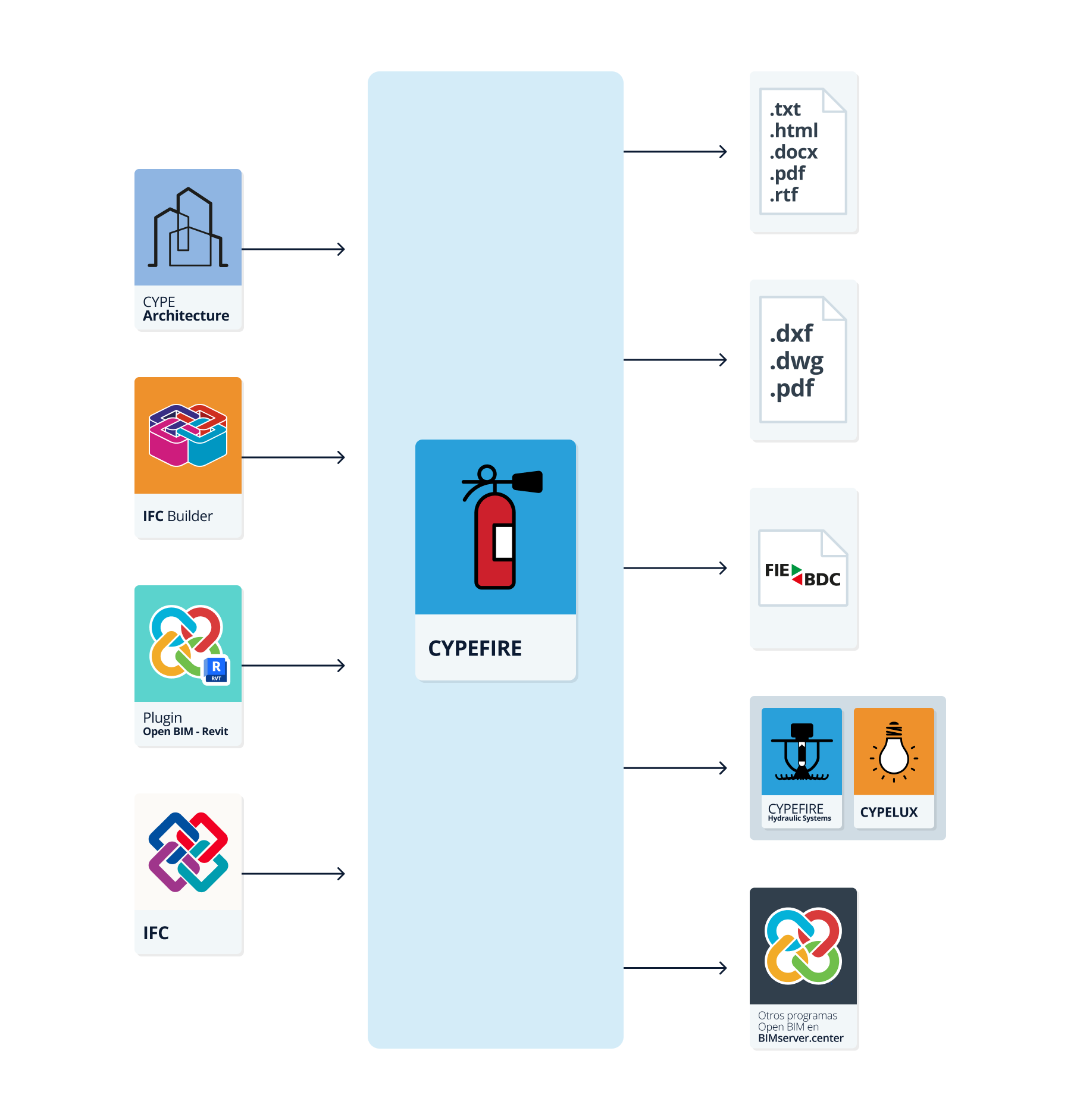
As CYPEFIRE is an Open BIM tool and is connected to the BIMserver.center platform, it offers different workflow options.
Data entry
Free definition
- Defining the elements of the model and their characteristics by means of free entry in CYPEFIRE.
- Defining the model elements and their characteristics in CYPEFIRE based on DXF/DWG, DWF templates or images (.jpeg, .jpg, .bmp, .wmf).
Importing BIM models
If the CYPEFIRE job is linked to a BIM project on the BIMserver.center platform, the following can be carried out:
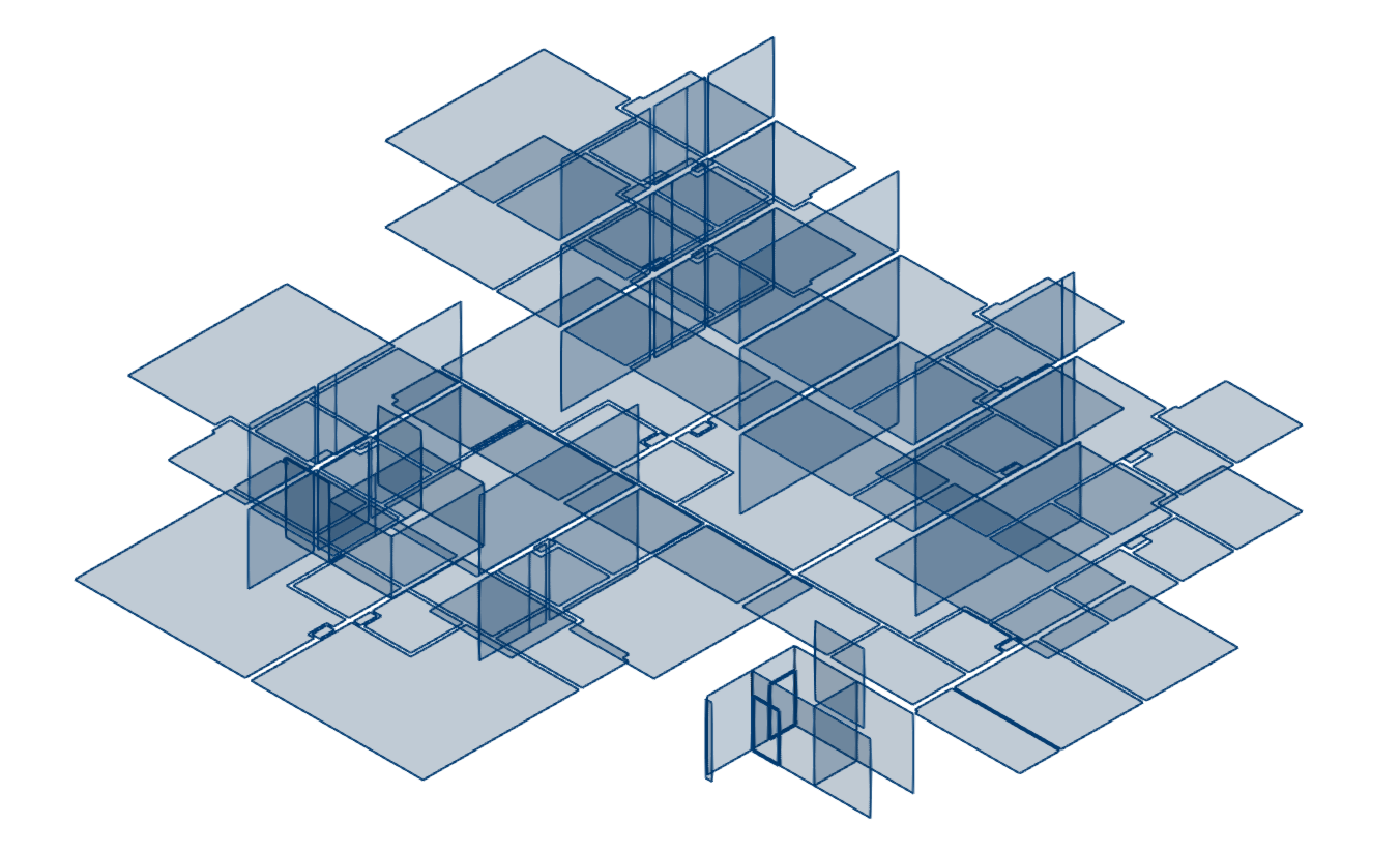
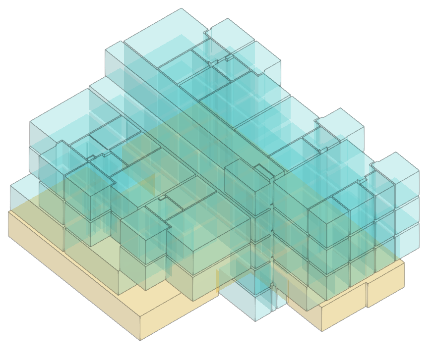
- Importing the model with the geometry of a building. This allows users to generate the floor plan of the building and import the layout of the spaces, to subsequently create and assign the indoor compartmentation, define the outdoor propagation cases and enter the rest of the elements (such as fire loads, evacuation routes, fire protection equipment or fire brigade intervention elements) based on this geometry. Possible options include the following:
- Importing models designed in CYPE Architecture.
- Importing models designed in IFC Builder.
- Importing models in IFC format (generated by CAD/BIM programs such as Allplan, ArchiCAD and others) uploaded to the BIMserver.center project via the web platform.
- Importing models designed in Autodesk Revit with the Open BIM - Revit Plugin.
Data output
- Exporting the reports to HTML, DOCX, PDF, RTF and TXT formats.
- Exporting the drawings to DXF, DWG and PDF formats.
- Exporting the bill of quantities to FIEBDC-3 format.
- Exporting the information contained in CYPEFIRE to the BIMserver.center platform using IFC formats. This allows it to be viewed by authorised project participants. The information generated by CYPEFIRE can be used by the following programs:
- CYPEFIRE Hydraulic Systems
Sizing and designing of hydraulic fire extinguishing networks using sprinklers and fire hose reels. Imports sprinkler installation requirements from CYPEFIRE. - CYPELUX
Lighting calculations for normal and emergency lighting installations. Imports evacuation routes and fire protection equipment layout from CYPEFIRE.
- CYPEFIRE Hydraulic Systems
Work environment
The CYPEFIRE interface presents two tabs with different work environments: "Installation" and "Bill of quantities". Both environments are similar to those in other CYPE tools and have a system of dockable windows that can be customised to adapt the workspace to the project's needs.
"Installation" tab
The tab activated by default when launching the program is the "Installation" tab. This presents a work environment that allows users to quickly and easily design the installation, both in a 3D view and in any type of 2D view (such as floor plans and elevations). This way, the elements of the installation can be entered using the most appropriate view at any given moment.
The tab dislays the following:
- The top toolbar contains the tools for managing the general characteristics of the model; entering and editing fire loads, compartmentation, outdoor propagation, evacuation, equipment and firefighter intervention elements; using the editing tools; and carrying out the analysis, checking and design of the system.
- The modelling area, on the right-hand side of the screen, is where all the elements of the project are entered, edited and displayed.
- On the left-hand side, there are several panels with tools for defining the views and levels of the project and for managing the visibility of the elements read and the own elements.

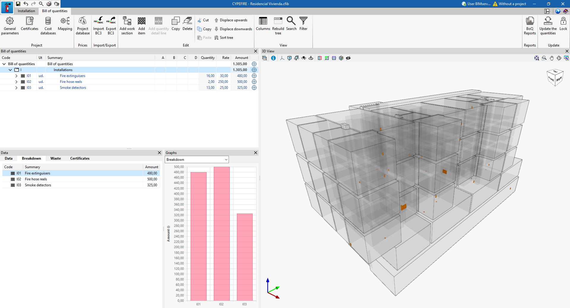
“Bill of quantities” tab
The "Bill of quantities" tab is used to manage the bill of quantities of the elements in the system (such as fire extinguishers, fire hose reels, alarm systems or signals), and shows the following:
- A top toolbar with tools for creating and editing the bill of quantities, as well as tools for managing and creating reports.
- A graphic window with its own toolbar, located on the right-hand side, where the different elements of the job can be displayed.
- On the left-hand side, a specific area for structuring the bill of quantities.
Data input and output sequence for the design and verification of fire safety rules for a building
The design and verification of compliance with the fire safety rules of a building can be carried out in the program using the following input and output sequence:
- Creating a new job (from "File", "New").
- (Optional) Linking to BIMserver.center, importing spaces by reference or type and assigning occupancy parameters.
- Revising the project's general options ("Project > General options"): importing codes or configuring applicable checks in a customised way.
- Defining types of fire protection equipment. This can be done in two additional ways:
- Loading manufacturers' catalogues (from “Project”, “Catalogue management”).
- Loading or manually entering the generic element libraries (from "Project", "Generic element library").
- (Optional) Manually entering the spaces (from "Compartmentation", "Space") if they have not been read and generated from the BIM model.
- Creating compartments such as fire compartments, establishments, use units, stairways, risk rooms, protected lobbies and protected zones (from the "Compartmentation" or "Project", "Entered elements").
- Assigning spaces to the compartments created (from "Compartmentation", "Assign").
- Defining outdoor propagation cases ("Outdoor propagation" group).
- Entering and marking out evacuation routes and evacuation origins, and sign layout ("Evacuation" group).
- Arranging fire protection equipment ("Equipment" group).
- Defining the elements describing the fire brigade intervention ("Intervention of firefighters" group).
- (Optional) Entering combustible elements and combustible building elements ("Fire loads" group).
- Analysing, checking and designing the elements in the model and consulting the results ("Analysis" group).
- (Optional) Managing and generating the bill of quantities ("Bill of quantities" tab).
- Obtaining reports and drawings (from "File", "Reports/Drawings").
- Exporting to BIMserver.center (from "BIMserver.center", "Share").
Managing the elements entered into the model
In the "Installation" tab, in the "BIM Model" group of the main toolbar, users can access the following option:

Entered elements
This option is used to access a series of tables containing the information of all the elements arranged in the model. Users can add, edit, delete or reorder the following elements:
- Fire loads
- Combustible elements
- Building elements
- Compartmentation
- Compartmentalising elements
- Fire-break doors
- Establishments
- Fire compartments
- Stairs
- Use units
- Risk rooms
- Protected lobbies
- Protected zones
- Spaces
- Outdoor propagation
- Roof-façade propagation
- Horizontal propagation
- Vertical propagation
- Evacuation
- Evacuation routes
- Evacuation origins
- Floor exits
- Risk room exits
- Signs
- Equipment
- Fire hose reels
- Dry standpipes
- Fire extinguishers
- Hydrants
- Alarm systems
- Detection systems
- Protection equipment signs
- Intervention of firefighters
- Manoeuvre spaces
- Access roads

If elements such as fire loads, partitions, evacuation elements, equipment or fire brigade intervention elements are graphically arranged in the model, the program will allow users to consult their numerical data through these tables, using either the "Entered elements" option or the "Edit in the list" option.
Setting the general options
DWithin the "Installation" tab, in the "BIM Model" group of the main toolbar, users can access the following option:

General options
This option allows users to set up the general data of the model and the checks applicable to the different elements:
- General options
- Calculation options
- User configuration
- Report design
- Checks
- Checks applicable to establishments
- Checks applicable to fire compartments
- Checks applicable to stairs
- Checks applicable to risk rooms
- Checks applicable to protection lobbies
- Checks applicable to protected zones
- Checks applicable to the roof-façade propagation risk
- Checks applicable to the horizontal propagation risk
- Checks applicable to the vertical propagation risk
- Evacuation route
- Checks applicable to the manoeuvre space
- Checks applicable to the access road
All the general options should be defined or reviewed before continuing to work with the program. When entering elements into the model, such as compartments, escape routes or fire safety equipment, the program will need to define which check is applicable or which type is associated with each of the defined elements.
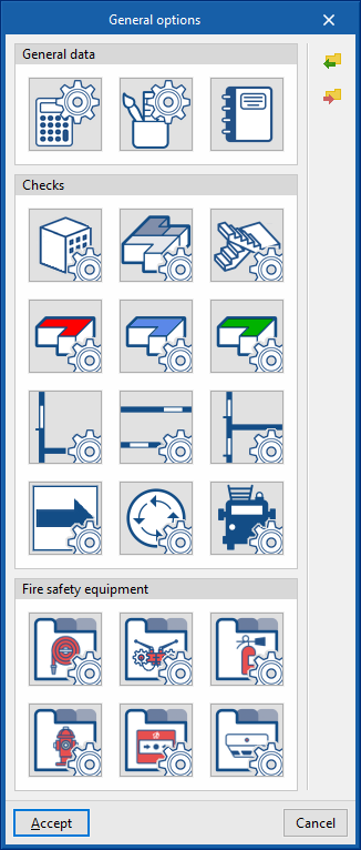
The options available in this panel are detailed below:
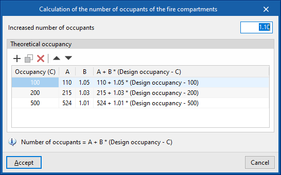
Calculation options
- Calculation of the number of occupants of the fire compartments
This adjusts the parameters for calculating the number of occupants in the project’s fire compartments:- Increased number of occupants
- Theoretical occupancy:
(Occupancy (C), A, B, A + B* (Occupancy calculation - C)
The number of occupants is calculated with the following expression:
Number of occupants = A + B * (Occupancy calculation - C)
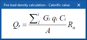
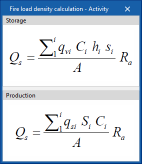
- Fire load density calculation
Allows users to choose the formula used to calculate the fire load density:- Calorific value
- Activity
- Perform error detection according to their importance (optional)
Displays the errors (from the ‘Show/Hide incidents’ option) in the program according to their importance, allowing them to be solved in stages, focusing on only one part of the problem at a time. If this option is deactivated, all the errors in the job are displayed simultaneously.

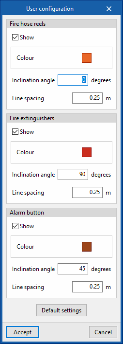
User configuration
This allows users to modify the display of the errors generated by the distribution of the following fire safety equipment:
- Fire hose reels
- Show (optional)
- Colour
- Inclination angle
- Line spacing
- Fire extinguishers
- Show (optional)
- Colour
- Inclination angle
- Line spacing
- Alarm button
- Show (optional)
- Colour
- Inclination angle
- Line spacing
- Default settings
This option allows users to reload the default values.
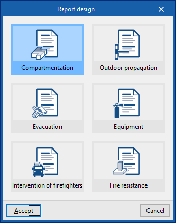
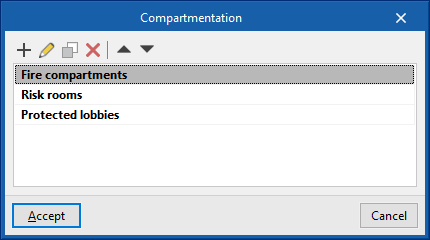
Report design
The reports available for configuration are as follows:
- Compartmentation
- Outdoor propagation
- Evacuation
- Equipment
- Intervention of firefighters
- Fire resistance
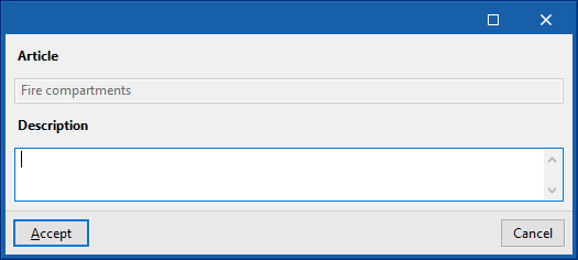
Items can be added to each of them and their description can be entered:
- Article
- Description
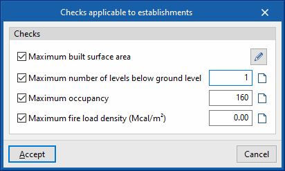
Checks applicable to establishments
Allows users to configure the checks applicable to the project's establishments. Each check to be applied can be activated and the associated "Item" and "Description" can be entered using the buttons available on the right-hand side of the dialogue box:
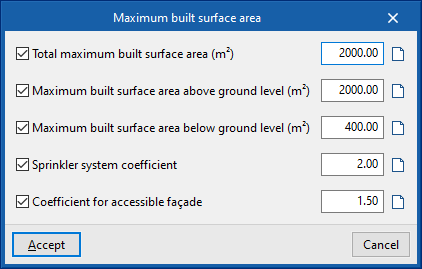
- Maximum built surface area
- Total maximum built surface area (m2)
- Maximum number of levels below ground level (m2)
- Sprinkler system coefficient
- Coefficient for accesible façade
- Maximum number of levels below
- Maximum occupancy
- Maximum fire load density (Mcal/m2)
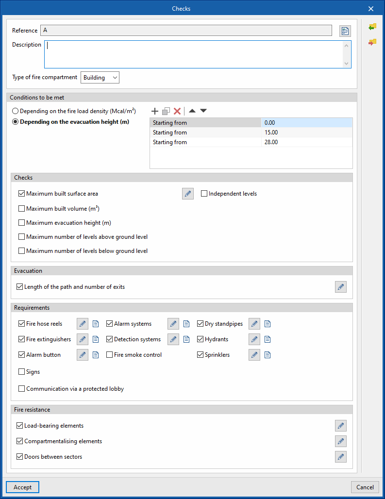
Checks applicable to fire compartments
Allows users to set up the checks applicable to each type of fire compartment in the project:
- Reference
- Description
- Type of fire compartment (Industrial/Building)
- Conditions to be met
This allows users to manage different groups of checks applicable in the fire compartment according to the calculated values of the following magnitudes:- Depending on the fire load density (Mcal/m2)
- Depending on the evacuation height (m)
- Checks
Each check to be applied can be activated and the associated "Item" and "Description" can be entered using the buttons available on the right hand side of the dialogue box:- Maximum built surface area (optional)
- Maximum built volume (optional)
- Maximum evacuation height (optional)
- Maximum number of levels above ground level (optional)
- Maximum number of levels below ground level (optional)
- Independent levels:
By activating this option, the fire compartment shall only group spaces belonging to the same level.
- Evacuation
This allows users to set the limits of the parameters defining the escape routes provided in this type of fire compartment:- Length of the path and number of exits (optional)
- Requirements
This allows users to define the requirements for fire safety equipment in this type of fire compartment:- Fire hose reels (optional)
- Fire extinguishers (optional)
- Alarm button (optional)
- Alarm systems (optional)
- Detection systems (optional)
- Fire smoke control (optional)
- Dry standpipes (optional)
- Hydrants (optional)
- Sprinklers (optional)
- Signs (optional)
- Communication via a protected lobby (optional)
- Fire resistance
This allows users to define the required fire resistance of the elements present in this type of fire compartment or that delimit it from other spaces:- Load-bearing elements (optional)
- Compartmentalising elements (optional)
- Doors between elements (optional)
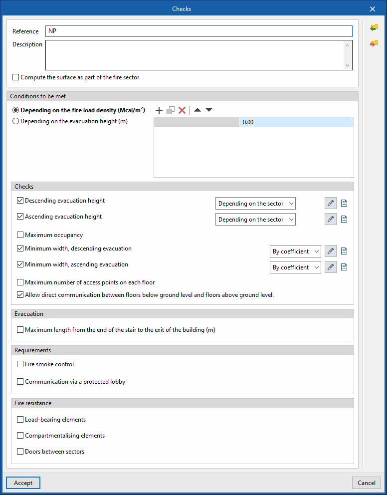
Checks applicable to stairs
Allows users to configure the checks applicable to each type of staircase in the project:
- Reference
- Description
- Compute the surface as part of the fire sector (optional)
This option allows the staircase area to be included as part of the fire sector to which it is assigned. - Conditions to be met
This allows users to manage different groups of checks applicable to the staircase according to the calculated values of the following magnitudes:- Depending on the fire load density (Mcal/m2)
- Depending on the evacuation height (m)
- Checks
Users can activate each check they want to be applied, as well as enter the "Item" and "Description" associated with each one using the buttons available on the right-hand side of the dialogue box:- Descending evacuation height (optional)
- Ascending evacuation height (optional)
- Maximum occupancy (optional)
- Minimum width, descending evacuation (optional)
- Minimum width, ascending evacuation (optional)
- Maximum number of access points on each floor (optional)
- Allow direct communication between floors below ground level and floors above ground level (optional)
- Evacuation
This allows users to set the limits of the parameters defining the evacuation routes laid out in this type of staircase:- Maximum length from the end of the stair to the exit of the building (m) (optional)
- Requirements
This allows the definition of the fire safety equipment requirements for this type of staircase:- Fire smoke control (optional)
- Communication via a protected lobby (optional)
- Fire resistance
This allows users to define the required fire resistance of the elements present in this type of staircase or that delimit it from other spaces:- Load-bearing elements (optional)
- Compartmentalising elements (optional)
- Doors between sectors (optional)
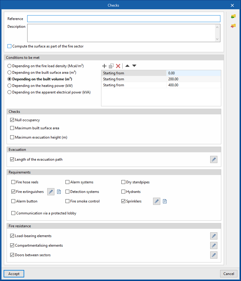
Checks applicable to risk rooms
Allows users to set up the checks applicable to each type of risk room in the project:
- Reference
- Description
- Compute the surface as part of the fire sector (optional)
This option allows the area of the risk room to be included as part of the fire sector to which it is assigned. - Conditions to be met
This allows users to manage different groups of checks applicable in the risk room according to the calculated values of the following quantities:- Depending on the fire load density (Mcal/m2)
- Depending on the built surface area (m2)
- Depending on the built volume (m3)
- Depending on the heating power (kW)
- Depending on the apparent electrical power (kVA)
- Checks
Users can activate each check that they want to apply, as well as enter the "Item" and "Description" associated with each one using the buttons available on the right-hand side of the dialogue box:- Null occupancy (optional)
- Maximum built surface area (optional)
- Maximum evacuation height (m)
- Evacuation
This allows users to set the limits of the parameters defining the evacuation routes provided in this type of risk room:- Length of the evacuation height (optional)
- Requirements
This allows users to define the requirements for fire safety equipment in this type of risk room:- Fire hose reels (optional)
- Fire extinguishers (optional)
- Alarm button (optional)
- Alarm systems (optional)
- Detection systems (optional)
- Fire smoke control (optional)
- Dry standpipes (optional)
- Hydrants (optional)
- Sprinklers (optional)
- Communication via a protected lobby (optional)
- Fire resistance
This allows users to define the required fire resistance of the elements present in this type of risk room or that delimit it from other spaces:- Load-bearing elements (optional)
- Compartmentalising elements (optional)
- Doors between elements (optional)
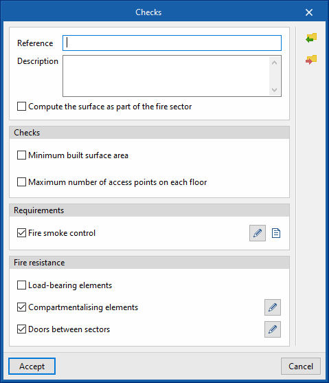
Checks applicable to protection lobbies
Allows users to set up the checks applicable to each type of protection lobby in the project:
- Reference
- Description
- Compute the surface as part of the fire sector (optional)
This option allows the surface of the protection lobbies to be included as part of the fire sector to which it is assigned. - Checks
Users can activate each check that they want to apply, as well as enter the "Item" and "Description" associated with each one using the buttons available on the right-hand side of the dialogue box:- Minimum built surface area (optional)
- Maximum number of access points on each floor (optional)
- Requirements
This allows users to define the requirements in this type of protection lobby:- Fire-smoke control (optional)
- Fire resistance
This allows users to define the required fire resistance of the elements present in this type of protection lobby or that delimit it from other spaces:- Load-bearing elements (optional)
- Compartmentalising elements (optional)
- Doors between elements (optional)
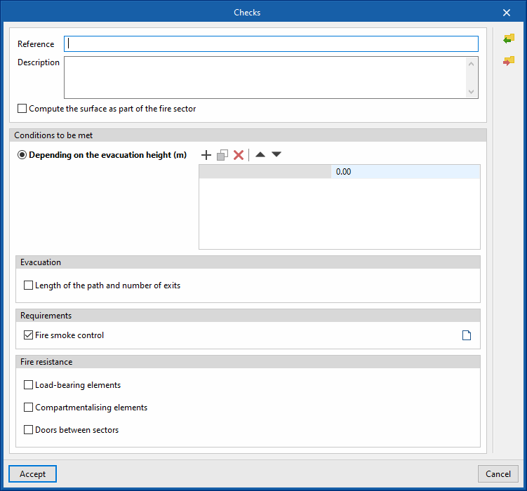
Checks applicable to protected zones
This allows users to set up the checks applicable to each type of protected zone in the project:
- Reference
- Description
- Compute the surface as part of the fire sector (optional)
This option allows the surface of the protected zone to be included as part of the fire sector to which it is assigned. - Conditions to be met
This allows users to manage different groups of checks applicable in the protected zone according to the calculated values of the following quantities:- Depending on the evacuation height (m)
- Evacuation
This allows users to set the limits of the parameters defining the evacuation routes provided in this type of protected zone:- Length of the path and number of exits (optional)
- Requirements
This allows the requirements in this type of protected zone to be defined:- Fire-smoke control (optional)
- Fire resistance
This allows users to define the required fire resistance of the elements present in this type of protected zone or that delimit it from other spaces:- Load-bearing elements (optional)
- Compartmentalising elements (optional)
- Doors between elements (optional)
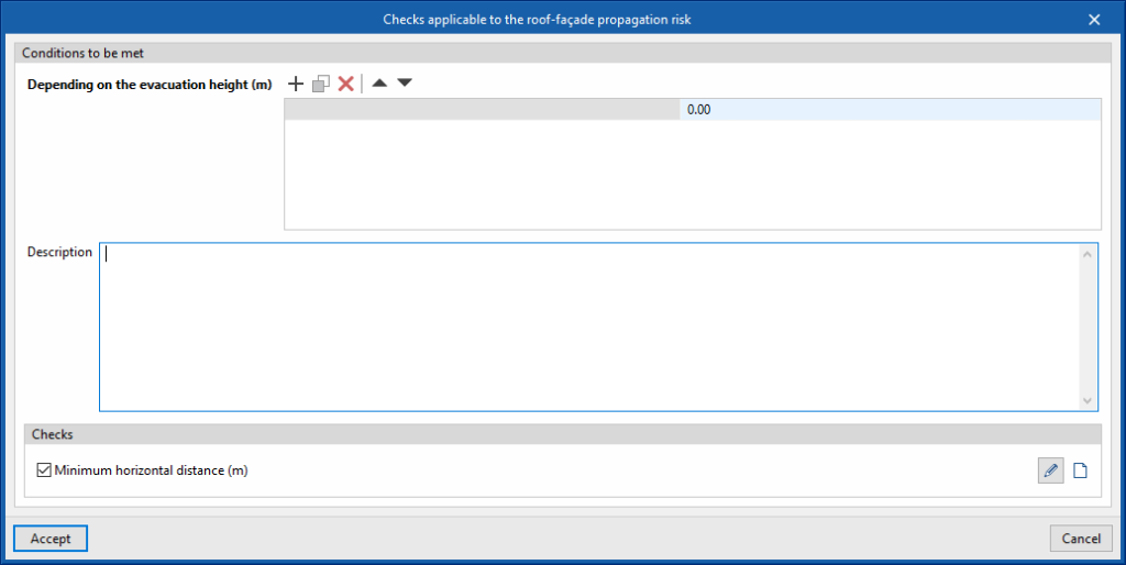
Checks applicable to the roof-façade propagation risk
Allows users to set up the checks applicable to the cases of roof-facade propagation defined in the project:
- Conditions to be met
This allows users to manage different applicable checks depending on the evacuation height:- Depending on the evacuation height (m)
- Description
- Checks
Activating this option applies the check shown. It is also possible to enter the associated "Item" and "Description" using the button available on the right-hand side of the dialogue box:- Minimum horizontal distance (m) (optional)
- Height (m) / Minimum distance (m)
- Minimum horizontal distance (m) (optional)
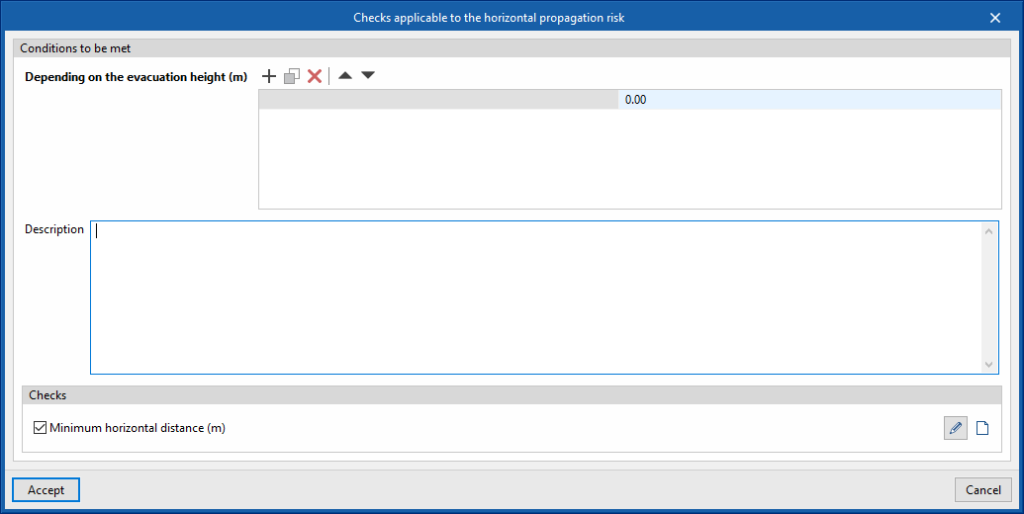
Checks applicable to the horizontal propagation risk
Allows users to set up the checks applicable to the horizontal propagation cases defined in the project:
- Conditions to be met
This allows users to manage different applicable checks depending on the evacuation height:- Depending on the evacuation height (m)
- Description
- Checks
Activating this option applies the check shown. It is also possible to enter the associated "Item" and "Description" using the button available on the right-hand side of the dialogue box:- Minimum horizontal distance (m) (optional)
- Angle (degrees) / Minimum distance (m)
- Minimum horizontal distance (m) (optional)
Checks applicable to the vertical propagation risk
Allows users to set up the checks applicable to the vertical propagation cases defined in the project:
- Conditions to be met
This allows users to manage different applicable checks depending on the evacuation height:- Depending on the evacuation height (m)
- Description
- Checks
Activating this option applies the check shown. It is also possible to enter the associated "Item" and "Description" using the button available on the right-hand side of the dialogue box:- Minimum vertical distance (m) (optional)

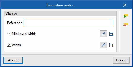
Evacuation route
Allows users to set up the checks applicable to the evacuation routes defined in the project:
- Checks
Users can activate each check they want to be applied, as well as enter the "Item" and "Description" associated with each one using the buttons available on the right-hand side of the dialogue box:- Reference
- Minimum width:
Defines a minimum width value in general and for the indicated occupancy values.- Minimum width
- Occupancy / Minimum width (m)
- Width
Defines the parameter for calculating the width of the evacuation routes:- Coefficient A:
The width is calculated with the following expression:
Width = Number of people / Coefficient A
- Coefficient A:
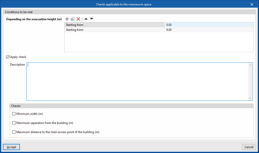
Checks applicable to the manoeuvre space
This is used to set up the checks applicable to the manoeuvre space defined in the project:
- Conditions to be met
- Depending on the evacuation height (m)
- Apply check (optional)
- Description
- Checks
Each check to be applied can be activated and the associated "Item" and "Description" can be entered using the buttons available on the right-hand side of the dialogue:- Minimum width (m) (optional)
- Maximum separation from the building (m) (optional)
- Maximum distance to the main access point of the building (m)
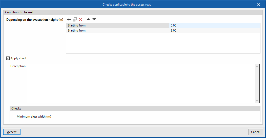
Checks applicable to the access road
This is used to set up the checks applicable to the access road defined in the project:
- Conditions to be met
- Depending on the evacuation height (m)
- Apply check (optional)
- Description
- Checks
- Minimum clear width (m) (optional)
Importing data from standards
To define the general data and checks on each element within those available in the "General options" panel, as well as the types of fire protection equipment available in the "Library of generic elements " panel, the program can import data from different codes using the options available on the right-hand side of the "General options" panel.
For fire safety equipment, new entries shall be generated in the tables for each piece of equipment, respecting the existing entries. If an existing entry has the same reference as the one obtained from the import, it shall respect it without generating a new entry or substituting data.

Managing element catalogues
In the "Project" group of the main toolbar of the "Installation" tab, there is an option to manage the manufacturer's product catalogues in order to incorporate them into the project:

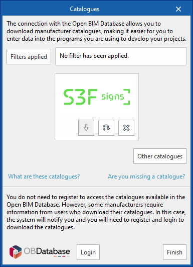
Managing catalogues
Downloads manufacturer catalogues using the connection to Open BIM Database, which makes it easier to enter data into the program for project development.
Clicking on this option opens a window with the available manufacturer catalogues.
Using the "Filters applied" option, filters can be applied by item "Category", "Language" and "Country" to show only manufacturers offering product catalogues with these characteristics.
Downloading catalogues
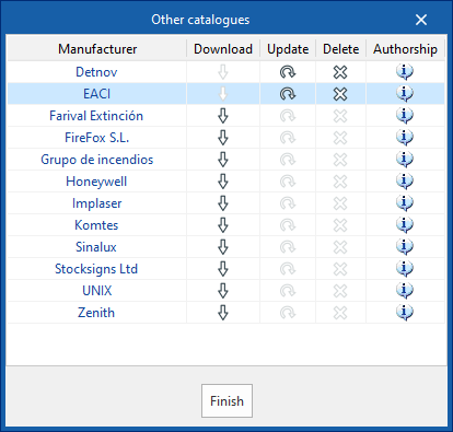
The following options are shown for each manufacturer:
- Download
Downloads the catalogue of the selected manufacturer. The products in the catalogue will be available in the project. - Update
Updates the selected manufacturer's catalogue to the latest version, deleting the version downloaded in the project.o. - Delete
Deletes the catalogue of the selected manufacturer. The products in the catalogue will no longer be available in the project.
Other catalogues
This option is used to download and update other available manufacturer catalogues.
Connecting with Open BIM Database
At the bottom of the dialogue box, the program allows users to log in with their Open BIM Database account and password.
The products from the downloaded catalogues can be selected when entering the elements in the installation.
Library of generic elements
In the "Project" group of the main toolbar of the "Installation" tab, there is an option to manage the library of generic elements in the pr

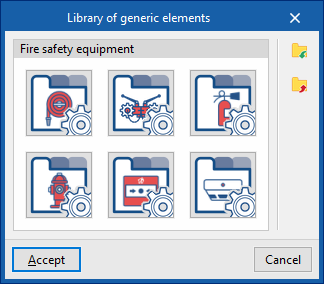
Library of generic elements
This option is used to manage libraries of fire protection equipment, including the following:
- Fire safety equipment
- Fire hose reels
- Dry standpipes
- Fire extinguishers
- Hydrants
- Alarm systems
- Detection systems
Subsequently, when entering fire safety equipment in the model using the options in the "Equipment" group, the program loads the data from the manufacturer's catalogues or one of the types previously defined in this library.
The options available in this panel are detailed below:
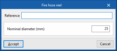
Fire hose reels
Provides access to the table of fire hose reel types. The following parameters are defined in each of them:
- Reference
- Nominal diameter (mm)
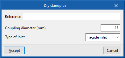
Dry standpipes
Provides access to the table of dry standpipe types. The following parameters are defined in each of them:
- Reference
- Coupling diameter (mm)
- Type of inlet (Façade inlet / Outlets on plan)
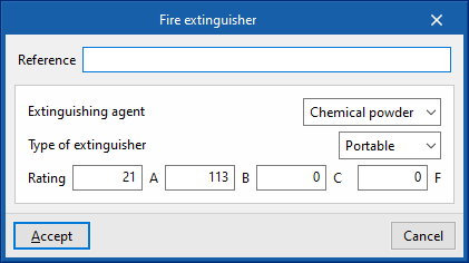
Fire extinguishers
Provides access to the table of fire extinguisher types. The following parameters are defined in each of them:
- Reference
- Extinguishing agent (Chemical powder / CO2 / Pulverized water)
- Type of extinguisher (Portable / With trolley)
- Rating (A / B / C / F)
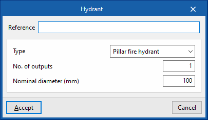
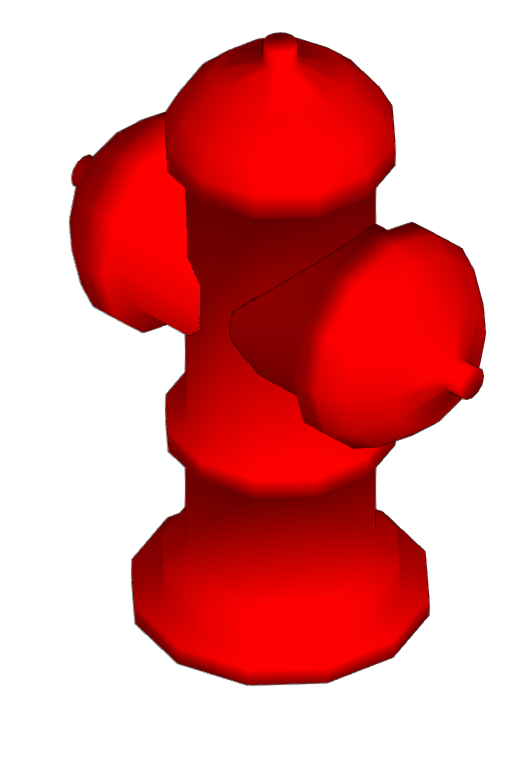
Hydrants
Provides access to the table of hydrant types. The following parameters are defined in each of them:
- Reference
- Type (Pillar fire hydrant / Underground fire hydrant)
- Number of outputs
- Nominal diameter (mm)
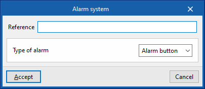
Alarm systems
Provides access to the table of alarm system types. The following parameters are defined in each of them:
- Reference
- Type of alarm (Alarm button / Optical device / Sound device)
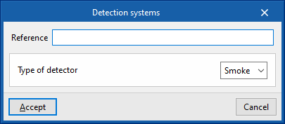
Detection systems
This provides access to the table of detection system types. The following parameters are defined in each of them:
- Reference
- Type of detector (Smoke / Heat)
Entering fire loads
The program is used to enter fire loads into the model and to calculate the fire load density in each compartment of the building. This subsequently affects the checks carried out on the compartments, which may vary according to the calculated fire load density value.
In the "Installation" tab, in the "Fire loads" group of the main toolbar, the following elements can be defined and entered:

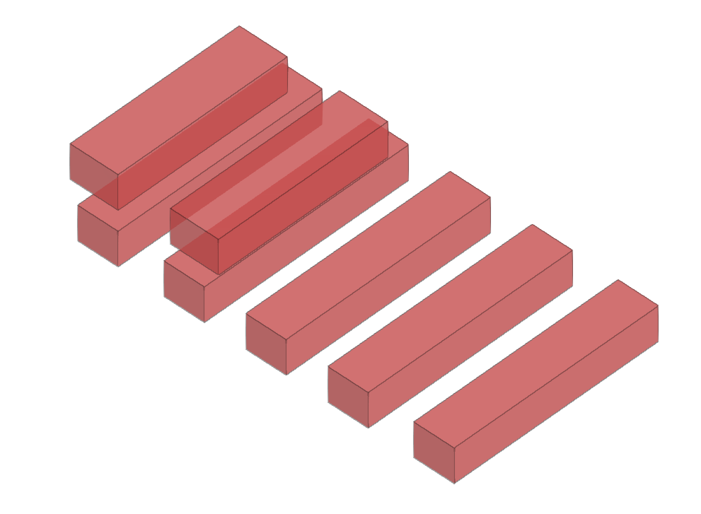
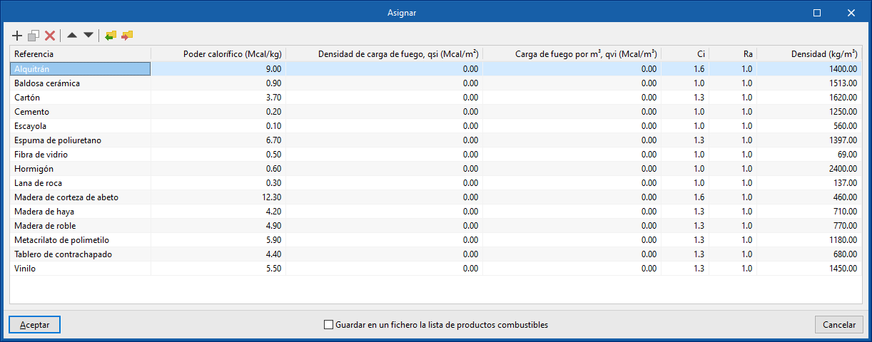
Fuel element
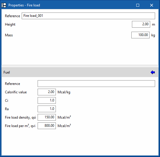
This option allows fuel elements to be entered into the model, such as material stockpiles or storage spaces for different products. To do so, its volume is defined by entering its plan shape and height and the parameters of the fuel material are set.
- Reference
- Height (m)
- Surface (m2)
This data can be viewed and edited after the fuel element has been entered into the model. If necessary, its value can be forced by using the "Lock/unlock the value of "Surface" option. - Mass (kg)
- Fuel
Allows users to define the parameters of the fuel material:- Reference
- Calorific value (Mcal/kg)
- Ci
- Ra
- Fire load density, qsi (Mcal/m2)
- Fire load per m3, qvi (Mcal/m3)
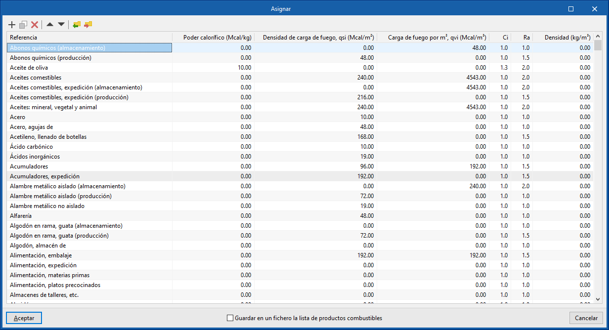
List of combustible products products
The program has a help feature on the right-hand side of the panel to "Assign" this data from the selection made in a list of combustible products.
This list of combustible products can be configured by entering the data in the table manually, and can also be imported or exported to a file on disk in CFG format using the corresponding options.
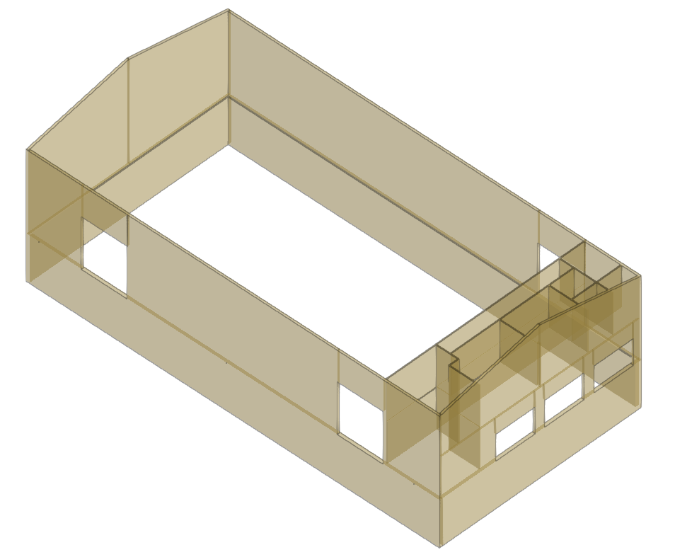
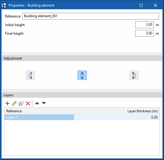
Building element
This option is used to enter building elements made up of combustible products. To do so, the geometry is defined by entering its plan layout and height, and the parameters of the combustible material of each of the layers of which they are composed are established:
- Reference
- Initial height (m)
- Final height (m)
- Adjustment
- The wall is situated to the right of the introduced line
- The wall is centred on the introduced line
- The wall is situated to the left of the introduced line
- Layers
Allows users to define the layers of combustible material that make up the building element.- Reference
- Layer thickness (m)
- Fuel
Defines the parameters of the fuel material:- Reference
- Calorific value (Mcal/kg)
- Ci
- Density (kg/m3)
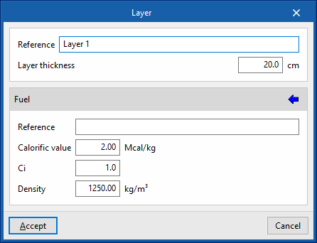
List of combustible products
Just like the fuel elements, the program has a help feature on the right-hand side of the editing panel of each layer to "Assign" this data from the selection made in a list of combustible products.
Once the fire loads have been entered and the job has been calculated, users can consult the calculated fire load density value in the editing panel of each of the compartments. These panels are accessed from the "Entered elements" or "Edit in the list" options.
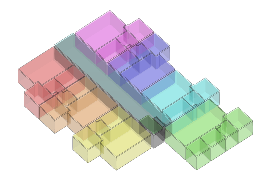
Defining the interior compartmentation
Interior compartmentation is one of the main elements in the fight against the spread of fire. This program allows the building to be compartmentalised against fire, including its sectorisation, as a means of passive protection. This means that the spaces are separated from the rest of the compartments by fire-resistant building elements for a certain amount of time. The purpose of interior compartmentation is to prevent the spread of fire from one compartment to the others.
Within the "Installation" tab, in the "Compartmentation" group of the main toolbar, the following elements can be defined and entered:

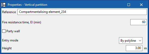
Vertical partition
Allows users to enter a vertical partition in the model manually. For this purpose, the following characteristics are defined:
- Reference
- Fire resistance time, EI (min)
- Party wall (optional)
This option allows users to indicate that the partitioning element is the boundary of the building. - Entry mode (By polyline / By points)
- Height (m)
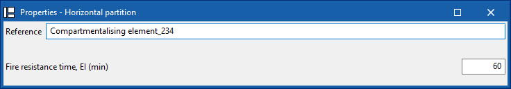
Horizontal partition
Allows a horizontal partition to be manually inserted into the model. For this purpose, the following characteristics are defined:
- Reference
- Fire resistance time, EI (min)
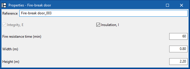
Fire-break door
Allows a fire-break door to be manually inserted into the model. For this purpose, the following characteristics are defined:
- Integrity, E
- Insulation, I (optional)
- Fire resistance time, EI (min)
- Width (m)
- Height (m)
Fire-break doors must be fitted over vertical partitions which have been inserted previously.
This means that the partitions and fire-break doors do not have to be entered manually. Before the program can generate the partitions and fire doors correctly, users must first assign the spaces to compartments.
The application distinguishes between the following types of compartments:
- Fire compartment
- Establishments
- Use units
- Staircases
- Risk rooms
- Protected lobbies
- Protected zones
Fire compartment
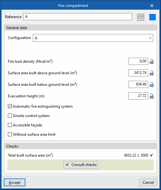
Allows a fire compartment to be entered into the model and its characteristics to be defined:
- Reference
Allows users to enter the reference of the fire compartment. - Spaces
Allows users to consult the spaces that are assigned to the fire compartment. To assign spaces to the fire compartment, the "Assign" option of the "Compartmentation" group in the general interface is used. The program displays a table showing the reference of these spaces and the floor where they are located:- Reference, Story
- Colour
Allows users to define the representation colour of the fire compartment. - General data
- Configuration
Allows users to select the checks applicable to the fire compartment. These can be created and edited from "General options" in the "Project" group of the general interface. - Activity (optional)
Allows users to define the activity of the fire compartment. This option only appears if checks applicable to "Industrial" type fire sectors have been selected. - Fire load density (Mcal/m2)
Allows users to enter the fire load density value of the fire compartment. If fire loads have been defined in the model, clicking on the corresponding icon takes you to the "Justification of the fire load density" window, which displays the information on the fuel elements and the building elements entered. - Surface area built above ground level (m2), Surface area built below ground level (m2), Evacuation height (m)
This allows users to consult the values of these parameters obtained from the model or to type in their values directly. If the padlock icon is unlocked, the program will update the value of each parameter when analysing the model. If it is locked, the program will not update the value during the analysis. - Automatic fire extinguishing system (optional)
Allows users to declare the existence of an automatic extinguishing system in the fire compartment. - Smoke control system (optional)
Allows users to declare the existence of a smoke control system in the fire compartment. - Accessible façade (optional)
Allows users to declare the existence of an accessible façade in the fire compartment. - Without surface area limit
Allows users to indicate that the compartment has no area limit, thus disabling the checks related to the area.
- Configuration
- Checks
This displays the checks carried out on the fire compartment based on the data indicated in its editing panel. To edit these checks, access the "General options" in the "Project" group of the general interface. It is also possible to obtain a report with the checks carried out on the fire area using the following option:- Consult checks
Establishments
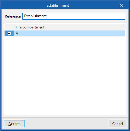
Allows users to enter an establishment in the model and define its characteristics. Establishments are areas of the building that group together the different fire compartments designed and operated under the same ownership:
- Referencia
Allows users to enter the reference of the establishment. - Fire compartment
Displays a table with the defined fire compartments. Activating the corresponding boxes indicates the fire compartments associated with the selected establishment.
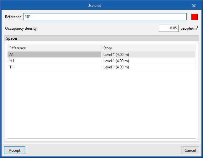
Use units
Allows users to enter use units in the model and to define their characteristics:
- Reference
Allows users to enter the reference of the use unit. - Colour
Allows users to define the representation colour of the use unit. - Occupancy density (people/m2)
Allows users to enter the occupancy density of the use unit. - Spaces
Allows users to consult the spaces that are assigned to the use unit. To assign spaces to a use unit, use the "Assign" option in the "Compartmentalisation" group of the general interface. The program displays a table showing the reference of these spaces and the floor on which they are located:- Reference, Story
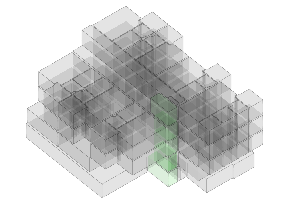
Staircases
Allows users to enter staircases in the model and define their characteristics:
- Reference
Allows users to enter the staircase reference. - Spaces
Allows users to consult the spaces that are assigned to the staircase. To assign spaces to a staircase, use the "Assign" option in the "Compartmentalisation" group of the general interface. The program displays a table showing the reference of these spaces and the floor on which they are located:- Reference, Story
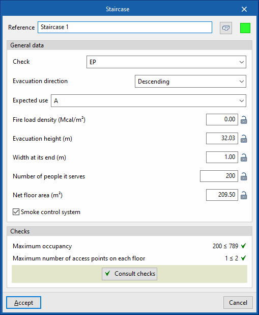
- Colour
Allows users to define the representation colour of the staircase. - General data
- Checks
Allows users to select the checks applicable to the staircase. These can be created and edited from "General options" in the "Project" group of the general interface. - Evacuation direction (Ascending / Descending)
Allows users to define whether the evacuation direction of the staircase is descending or ascending. - Expected use
Allows users to select the checks applicable to the associated fire compartment. These can be created and edited from "General options" in the "Project" group of the general interface. - Fire load density (Mcal/m2), Evacuation height (m), Width at its end (m), Number of people it serves, Net floor area (m2)
This allows users to consult the values of these parameters obtained from the model or to type in their values directly. If the padlock icon is unlocked, the program will update the value of each parameter when analysing the model. If it is locked, the program will not update the value during the analysis. - Smoke control system (optional)
Allows users to declare the existence of a smoke control system in the staircase.
- Checks
- Check
This shows the checks carried out on the staircase based on the data indicated in its editing panel. To edit these checks, access "General options" in the "Project" group of the general interface. It is also possible to obtain a report with the checks carried out on the staircase using the following option:- Consult checks
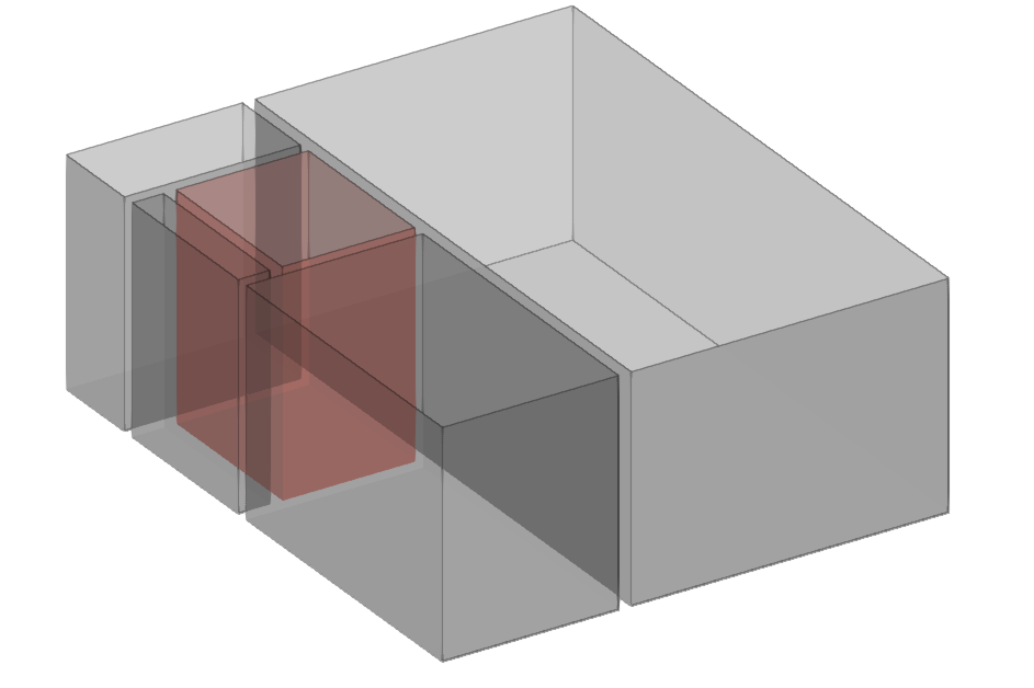
Risk room
This allows risk rooms to be entered into the model and their characteristics to be defined:
- Reference
Allows users to enter the reference of the risk room. - Spaces
Allows users to check the spaces that are assigned to the risk room. To assign spaces to a risk room, use the "Assign" option in the "Compartmentalisation" group of the general interface. The program displays a table showing the reference of these spaces and the floor on which they are located:- Reference, Story
- Colour
Allows users to define the representation colour of the staircase. - General data
- Configuration
Allows users to select the checks applicable to the risk room. These can be created and edited from "General options" in the "Project" group of the general interface. - Fire load density (Mcal/m2), Total built surface area (m2), Volume (m3), Apparent (kW), Apparent power (kVA)
This allows users to check the values of these parameters obtained from the model or to type in their values directly. If the padlock icon is unlocked, the program will update the value of each parameter when analysing the model. If it is locked, the program will not update the value during the analysis. - Automatic fire extinguishing system (optional)
Allows users to declare the existence of an automatic fire extinguishing system in the risk room. - Smoke control system (optional)
Allows users to declare the existence of a smoke control system in the risk room.
- Configuration
- Checks
This shows the checks carried out on the staircase based on the data indicated in its editing panel. To edit these checks, access "General options" in the "Project" group of the general interface. It is also possible to obtain a report with the checks carried out on the staircase using the following option:- Consult checks
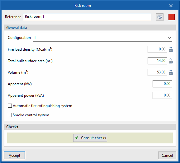
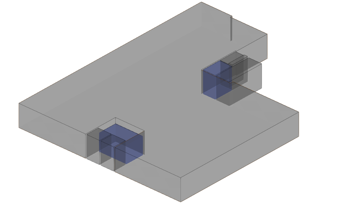
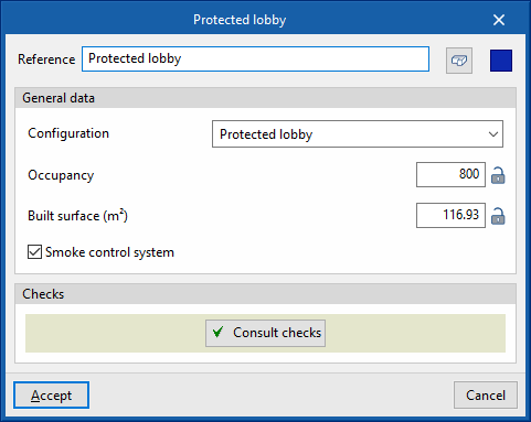
Protected lobbies
Allows users to enter protected lobbies in the model and define their characteristics:
- Reference
Allows users to enter the reference of the protected lobby. - Spaces
Allows users to consult the spaces that are assigned to the fire compartment. To assign spaces to the fire compartment, the "Assign" option of the "Compartmentation" group in the general interface is used. The program displays a table showing the reference of these spaces and the floor where they are located:- Reference, Story
- Colour
Allows users to define the representation colour of the protected lobby. - General data
- Configuration
Allows users to select the checks applicable to the protected lobby. These can be created and edited from "General options" in the "Project" group of the general interface. - Occupancy, Built surface (m2)
This allows users to consult the values of these parameters obtained from the model or to type in their values directly. If the padlock icon is unlocked, the program will update the value of each parameter when analysing the model. If it is locked, the program will not update the value during the analysis. - Smoke control system (optional)
Allows users to declare the existence of a smoke control system in the protected lobby.
- Configuration
- Checks
This shows the checks carried out on the protected lobby based on the data indicated in its editing panel. To edit these checks, access "General options" in the "Project" group of the general interface. It is also possible to obtain a report with the checks carried out on the protected lobby using the following option:- Consult checks
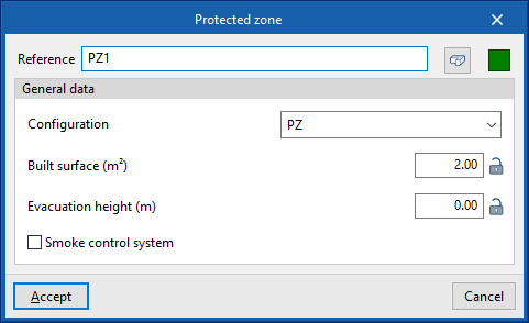
Protected zones
Allows users to enter the model's protected zones and define their characteristics. Protected zones are spaces delimited by fire-resistant compartmentalising elements, designed to allow occupants to evacuate the building and even to remain inside if necessary:
- Reference
Allows users to enter the reference of the protected zone. - Spaces
Allows users to check the spaces that are assigned to the protected zone. To assign spaces to a protected zone, use the "Assign" option in the "Compartmentation" group of the general interface. The program displays a table showing the reference of these spaces and the floor on which they are located:- Reference, Story
- Colour
Allows users to define the representation colour of the protected zone. - General data
- Configuration
Allows users to select the checks applicable to the protected zone. These can be created and edited from "General options" in the "Project" group of the general interface. - Built surface (m2), Evacuation height (m)
This allows users to consult the values of these parameters obtained from the model or to type in their values directly. If the padlock icon is unlocked, the program will update the value of each parameter when analysing the model. If it is locked, the program will not update the value during the analysis. - Smoke control system (optional)
Allows users to declare the existence of a smoke control system in the protected zone.
- Configuration
- Checks
This shows the checks carried out on the protected zone based on the data indicated in its editing panel. To edit these checks, access "General options" in the "Project" group of the general interface. It is also possible to obtain a report with the checks carried out on the protected zone using the following option:- Consult checks
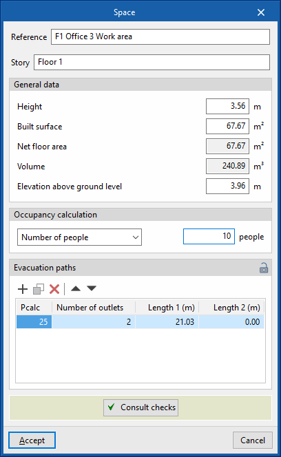
Space
Allows users to enter spaces in the model and define their characteristics:
- Reference
Allows users to enter the reference of the space. - Story
Allows users to enter the floor to which the space is assigned. - General data
- Height (m)
Height of the space volume. - Built surface (m2):
Parameter calculated by the program. - Net floor area (m2)
- Volume (m3)
Parameter calculated by the program. - Elevation above ground level (m)
Elevation at which the lower part of the volume of the space is positioned above the ground or ground level.
- Height (m)
- Occupancy calculation
Allows users to enter the occupancy of the space based on the occupancy density or the number of occupants.- Occupancy density (people/m2) / Number of people (people)
- Evacuations paths
Allows users to consult a table with the values of the parameters associated with the evacuation paths of the space. If the padlock icon is unlocked, the program will update the value of each parameter when analysing the model. If it is locked, the program will not update the value during the analysis.- Pcalc, Number of exits, Length 1, Length 2
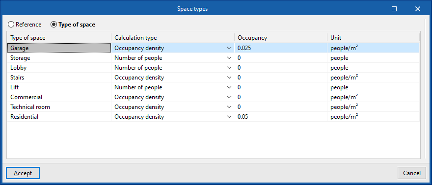
Importing spaces from the BIM model and assigning the occupancy
When a new job is started and linked to a BIMserver.center project with a geometric model that includes space information, or when the model is updated, the application launches a wizard that allows users to enter the number of occupants for each space. This can be done by "Reference" or "Space type". The occupancy can be given by "Number of persons" or by indicating the "Occupancy density".
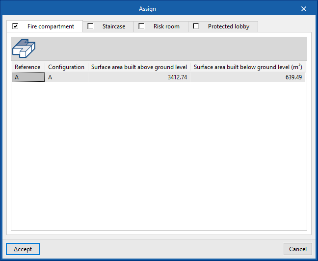
Assign
Allows users to assign spaces to one or more compartments. To do this, it opens an assignment window where the type of compartment is selected. The following compartments are available for space assignment:
- Fire compartment
- Staircase
- Use unit
- Risk room
- Protected lobby
- Protected zone
For the different compartment types to be available, they must first be created using the other options in the "Compartmentalisation" group or via the "Elements entered" option in the general interface.
Then, the spaces to be assigned to the selected compartments are selected in the model.
The assignment made can be viewed on the screen using the tooltip that appears when hovering over the room in the work area.
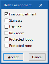
Delete
Allows users to delete the assignment of spaces to one or more compartments.
First, in the dialogue box, the compartments to be deleted from the space assignment are selected:
- Fire compartment
- Staircase
- Use unit
- Risk room
- Protected lobby
- Protected zone
Then, the spaces to be deleted are selected in the model.
Defining the outdoor propagation
One of the most dangerous factors in the event of a fire is the fire spreading outwards to other floors. To minimise this possibility, the program includes a series of minimum separation checks and obstacles to prevent the rapid spread of fire to the outside.
In the "Installation" tab, in the "Compartmentalisation" group of the main toolbar, users can define and enter cases of the three types of outdoor propagation that can be checked:

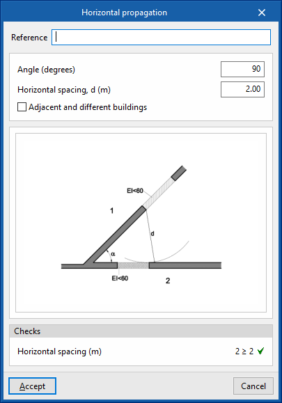
Horizontal propagation
This is used to enter the cases of horizontal outdoor fire propagation. In each case, the minimum measurements and distances necessary to prevent the spread of fire between opposite façades are checked according to the angle between them:
- Reference
Allows users to enter the reference of the horizontal propagation case. - Angle (degrees)
Allows users to enter the angle measurement between the façades facing each other. - Horizontal spacing, d (m)
Allows users to enter the horizontal spacing between the façades facing each other. - Adjacent and different buildings (optional)
Activating this option allows users to specify that this is a case of propagation between adjacent and different buildings, by varying the measurement of the horizontal spacing value. - Checks
Allows users to consult the checks carried out in the defined case of horizontal propagation.
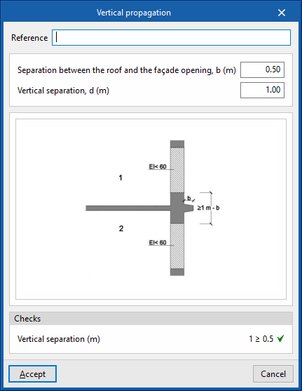
Vertical propagation
This is used to enter the cases of vertical outdoor propagation. In each case, the minimum measures and distances necessary to prevent the spread of the fire to the upper floors of the building are checked.
- Reference
Allows users to enter the reference of the vertical propagation case. - Separation between the roof and the façade opening, b (m)
- Vertical separation, d (m)
Allows users to enter the vertical separation measurement between openings in the façade. - Checks
Permite consultar las comprobaciones realizadas en el caso definido de Allows users to consult the checks carried out in the defined case of vertical propagation.
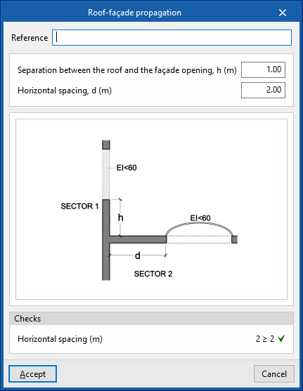
Roof-façade propagation
This is used to enter the cases of external roof-to-facade propagation. In each case, the minimum measurements and distances necessary to prevent the spread of fire through the roof to a nearby façade are checked.
- Reference
Allows users to enter the reference of the roof-facade propagation case. - Separation between the roof and the façade opening, b (m)
Allows users to enter the measurement between the roof and the opening in the nearby façade. - Horizontal separation, d (m)
Allows users to enter the horizontal separation measurement between the roof opening and the nearby façade. - Checks
Allows users to consult the checks carried out in the defined case of roof-facade propagation.
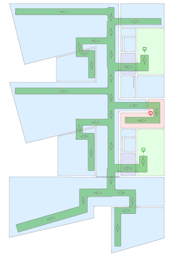
Defining the evacuation
Checks relating to the evacuation of the different areas of buildings and establishments are the main measures to safeguard the lives of occupants and workers. CYPEFIRE has all the possible tools to check and design the necessary escape routes for evacuation.
In the "Installation" tab, in the "Evacuation" group of the main toolbar, are the program's main features for checking and designing evacuation routes:

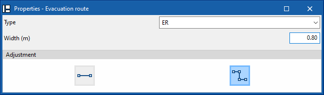
Evacuation route
Allows users to enter evacuation routes in the model. The layout of the escape routes defines the routes to meet the minimum distance and number of exit requirements defined in the project.
- Type
Allows users to select the type of escape route. These can be created and edited from the "General options" in the "Project" group of the general interface. - Width (m)
Defines the width of the evacuation route. - Adjustment
The program offers different geometrical settings for entering the escape route into the model:- Segment
Enters an evacuation route using an independent segment defined by its start point and end point. - Polyline
Enters a multi-segment evacuation route using a polyline defined by a polygonal line of points.
- Segment
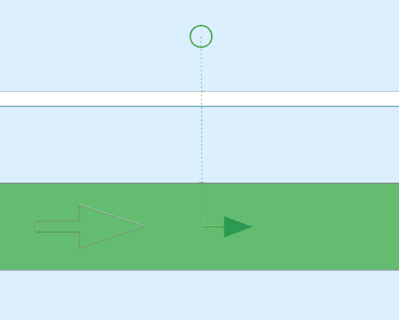
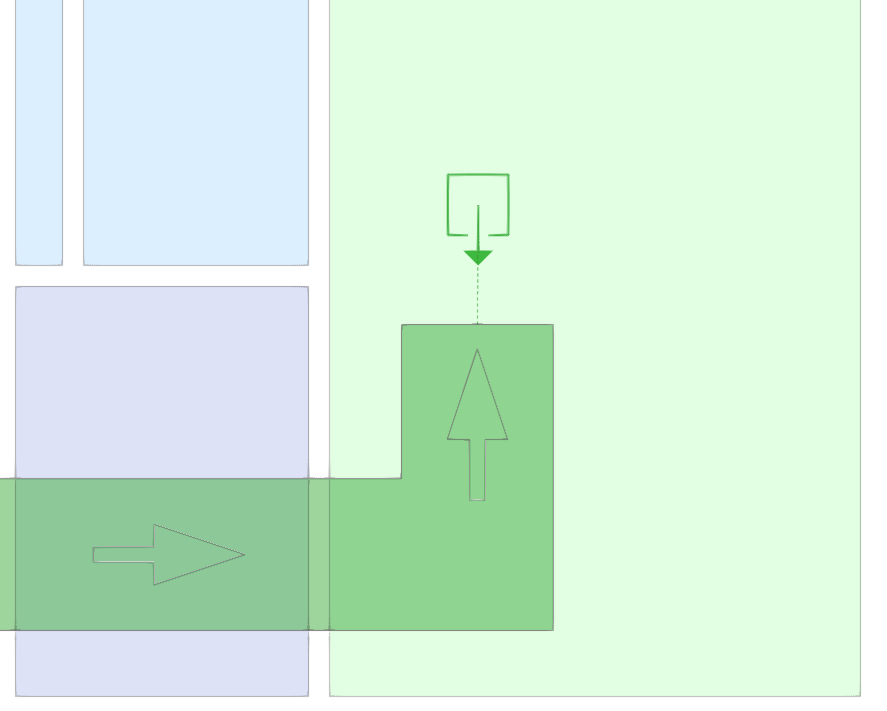
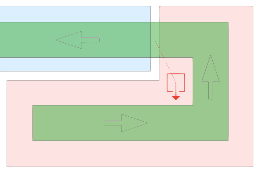
Evacuation origin
Allows users to enter an evacuation origin in the model. Evacuation origins are used to associate the occupancy (or part of it) of a space to a previously entered evacuation route, and thus to check the evacuation routes, lengths and exits.
This tool can be used to consider the evacuation of those spaces which, due to their characteristics, do not require an evacuation route in their interior (dwellings) or which, due to their size or geometry, do not require one either.
This can also be used to distribute the occupancy of a single space over different sections of the evacuation route.
Exit
The program allows different types of exits to be entered into the model ("Floor exit" and "Risk room exit") which define the end of a type of evacuation route. They are associated with a given point of a previously entered evacuation route.
- Floor exit
This option allows users to select a point on an evacuation route to provide a floor exit in the model. - Risk room exit
This option allows users to select a point on an evacuation route to provide a risk room exit in the model.
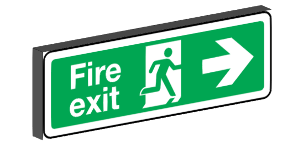
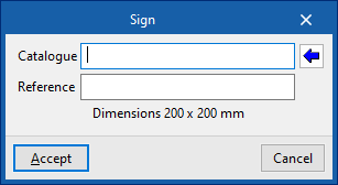
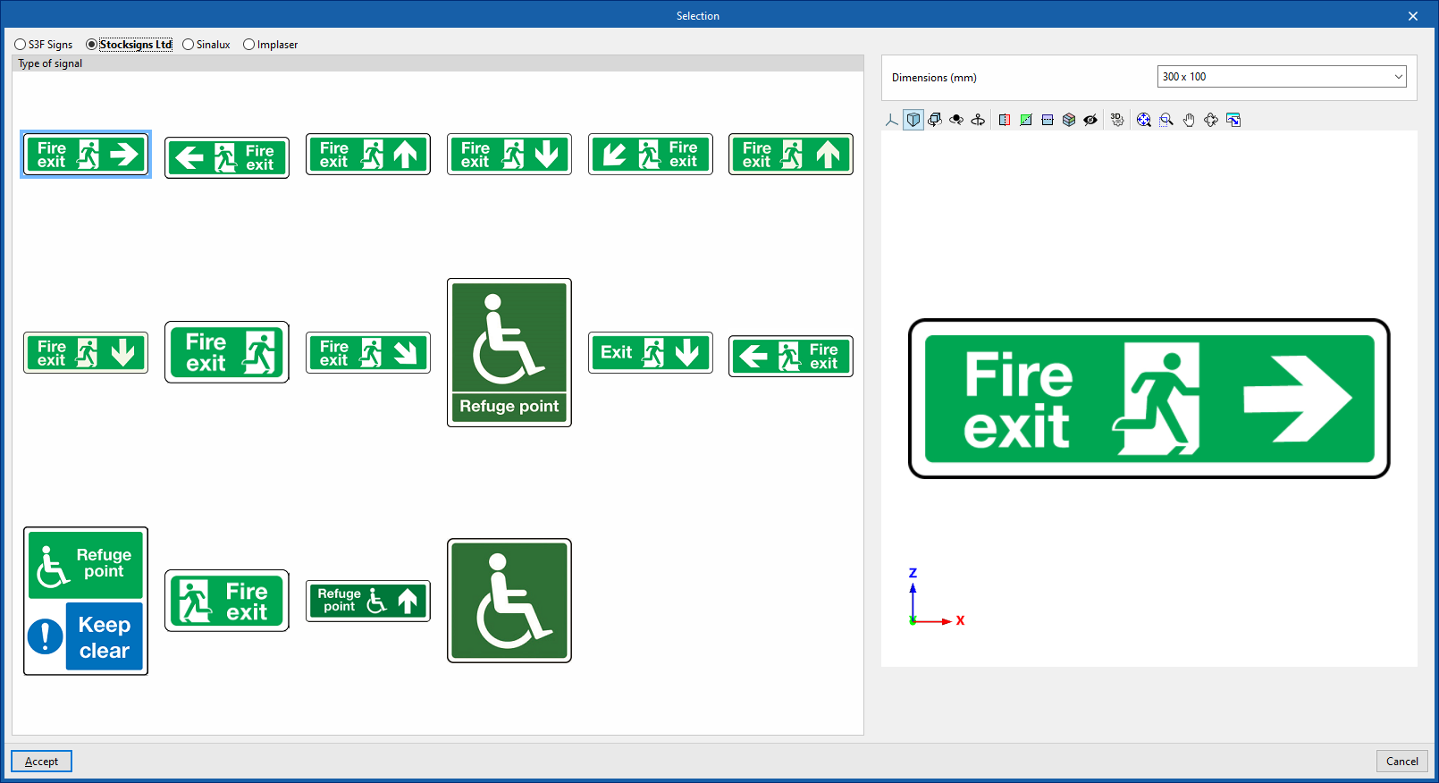
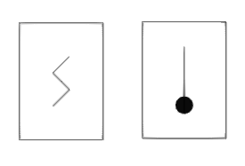
Sign
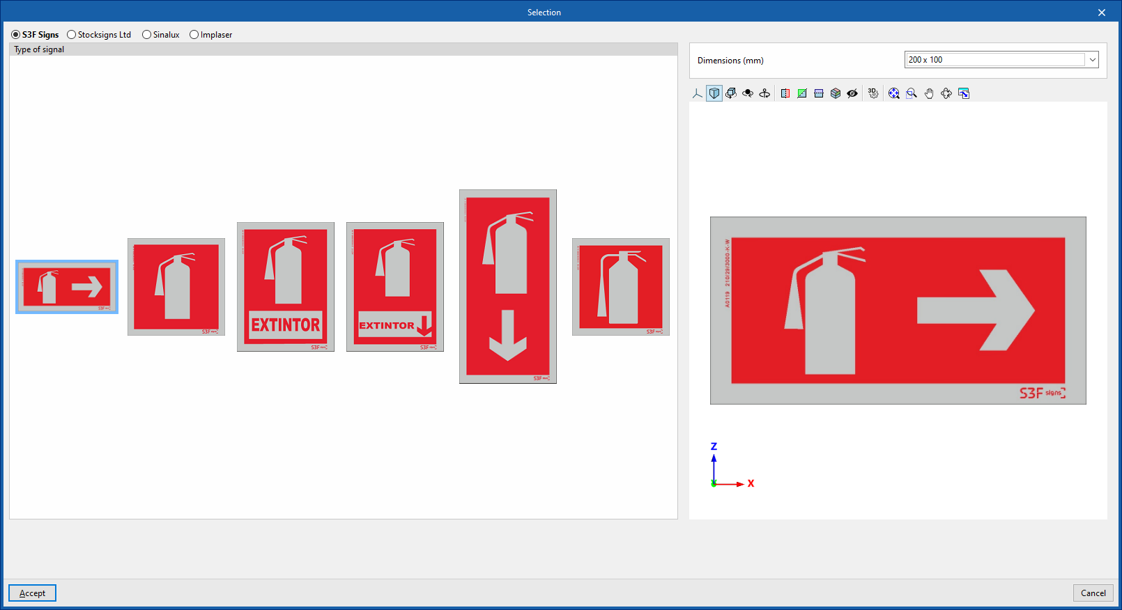
Allows users to enter a fire signal, such as an evacuation route signal, indicating the following parameters:
- Catalogue / Reference
By clicking on the help button on the right, one of the types of signs offered by the selected manufacturer can be loaded, and their "Dimensions" can be defined. The manufacturer catalogues can be managed from the "Catalogue management" option in the "Project" group of the general interface.
Entering fire safety equipment
Buildings and industrial establishments must have the necessary fire protection installations to enable fire detection, control and extinguishing according to the characteristics of the sectors.
In the "Installation" tab, in the "Equipment" group of the main toolbar, there are options for entering fire safety equipment:

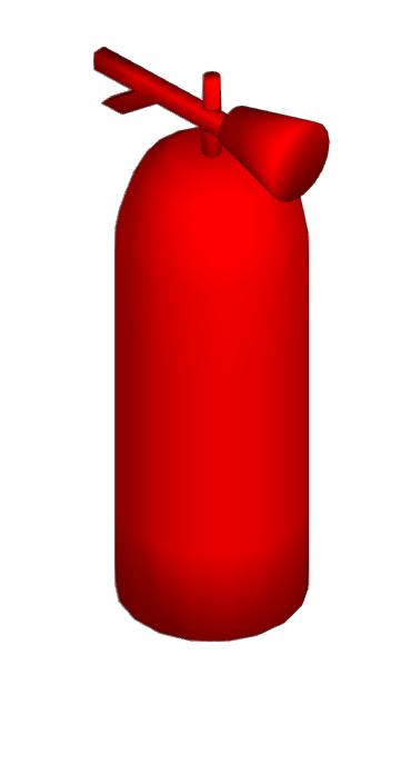
- Fire extinguishers
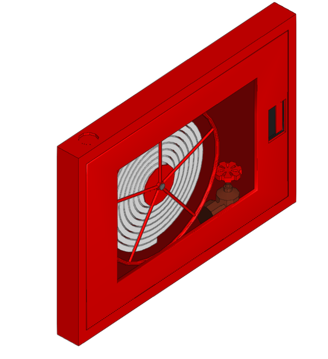
- Fire hose reels
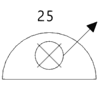
- Dry standpipes
Includes the supply inlet on the façade and the outlet on the ground floor.
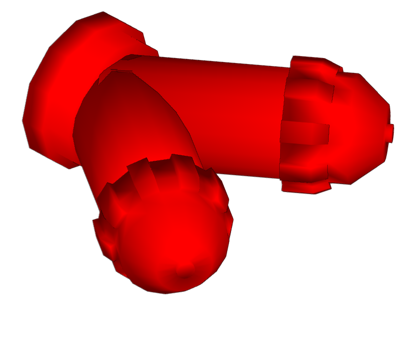
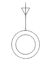
- Hydrants
- Alarm buttons


- Alarm systems
Includes acoustic sirens.


- Detection systems
Includes optical smoke detectors and thermo velocimetric detectors.
Defining fire protection equipment
The definition of the individual fire protection equipment is made when it is entered. For this purpose, the necessary information must be entered in the "Equipment" section, including the "Catalogue" and the "Reference".
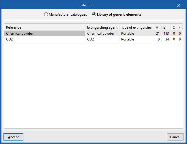
By clicking on the help button on the right-hand side, the "Selection" window opens, where it is possible to import this data from the manufacturer catalogues or from the program's generic element library:

- Manufacturer catalogues
Allows users to select the type of fire safety equipment from the generic element libraries. These can be managed from the "Catalogues" option in the "BIM Model" group of the general interface.- Manufacturer / Reference
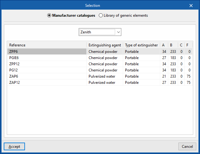
- Library of generic elements
Allows users to select the type of fire safety equipment from the generic element libraries. These can be created and edited from "General options" in the "BIM model" group of the general interface.- Reference
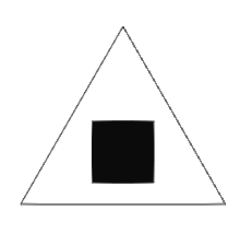
Signs for fire protection equipment
When entering fire safety equipment such as fire hydrants, fire extinguishers or detection systems, the program can define and enter their "Signs" simultaneously in the equipment.
By activating the "Selection by manufacturer catalogue" checkbox, the signal is defined. By clicking on the help button on the right, the "Catalogue" and the "Reference" of the product can be selected from the available sign manufacturers.

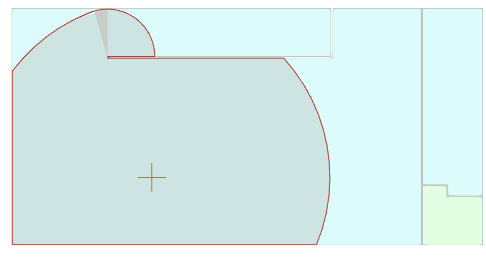
Area covered by fire protection equipment
When entering certain fire protection equipment such as equipped fire hydrants, fire extinguishers or alarm buttons, the program dynamically displays the area covered by their protection by means of shading.
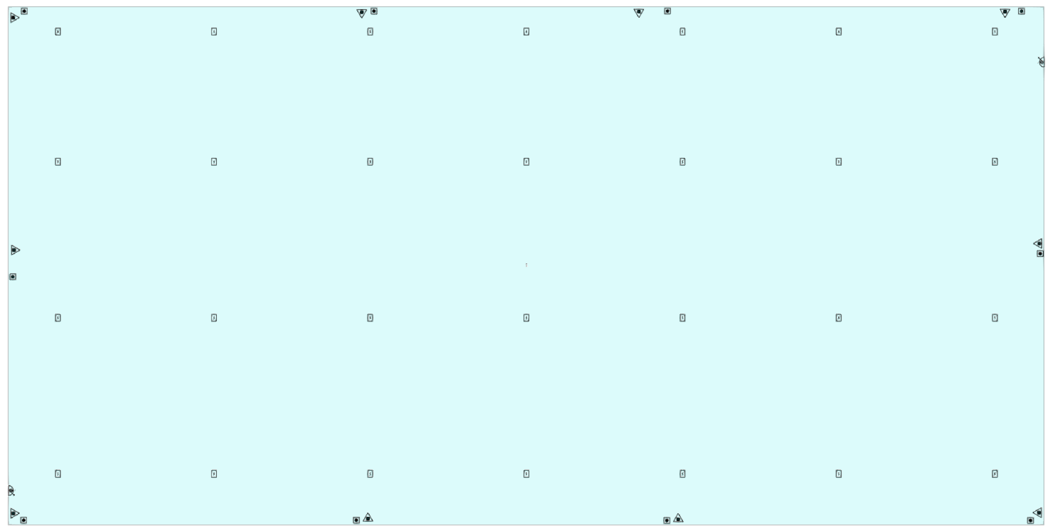
Symbols for fire protection equipment
To activate or deactivate the display of the symbols on the floor plan of the fire protection equipment, the "Show/Hide symbols" button in the "Own elements" panel, which is located by default at the bottom left of the general interface, can be used.
Defining the intervention of firefighters
In the "Installation" tab, in the " Intervention of firefighters" group of the main toolbar, the program has features to check the accessibility of firefighters to the site of the fire:

These features are the following:
- Access road (1)
- Manoeuvre space (2)
- Separation from the building (3)
- Distance to the main access point of the building (4)
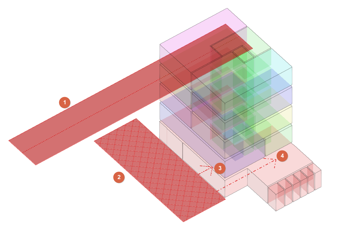
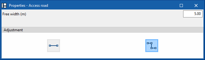
Access road
This allows users to enter an access road with the geometrical and resistance characteristics proposed by the standard so that the firefighting vehicle can reach the building. It allows the following properties to be defined:
- Free width (m)
- Adjustment
- Segment
- Polyline
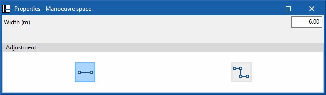
Manoeuvre space
Enters a manoeuvre space close to the building to allow the firefighting vehicle to be in the best position to extinguish the fire or evacuate the occupants through the façade. It allows the following properties to be defined:
- Width (m)
- Adjustment
- Segment
- Polyline
Separation from the building
This indicates the separation of the building from the manoeuvre space.
Distance to the main access point of the building
This indicates the distance to the main access to the building from the manoeuvre space.
Editing tools
In the "Installation" tab, in the "Edit" group of the main toolbar, users can find the following tools for editing the elements of the model:

The tools area in this group allows the following operations to be performed:
| Edit in the list | Edits the parametric properties of the selected element in the model. | |
| Delete | Deletes a previously entered element. | |
| Copy | Creates a copy of one or more elements. | |
| Move | Moves an element or a node of an element. | |
| Rotate | Rotates an element about the "x", "y" or "z" axis. | |
| Move a group of elements | Moves a group of elements. | |
| Symmetry (move) | Moves a selection of elements with symmetry about a vertical plane defined by two points. | |
| Invert | Reverses the direction of the evacuation routes. | |
| Measure lengths on plan | Measures lengths between defined points on the model. If a closed contour is selected, it also indicates the area. |
Analysis, checks and design
In the "Installation" tab, the "Analysis" group of the main toolbar contains the options for calculating, checking and designing the model elements:

Analysis
Clicking on this button launches the verification process of the checks applicable to the elements in the model. This will check whether the parameters of the fire protection systems entered are within the admitted criteria.
It also updates the unlocked data of the different elements entered in the model.
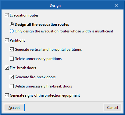
Design
This option launches the processes of automatic design, generation and deletion of the following elements, depending on the configuration defined in the editing panel:
- Evacuation routes (optional)
- Design all the evacuation routes
- Only design the evacuation routes whose width is insufficient
- Partitions (optional)
- Generate vertical and horizontal partitions (optional)
- Delete unnecessary partitions (optional)
- Fire-break doors (optional)
- Generate fire-break doors (optional)
- Delete unnecessary fire-break doors (optional)
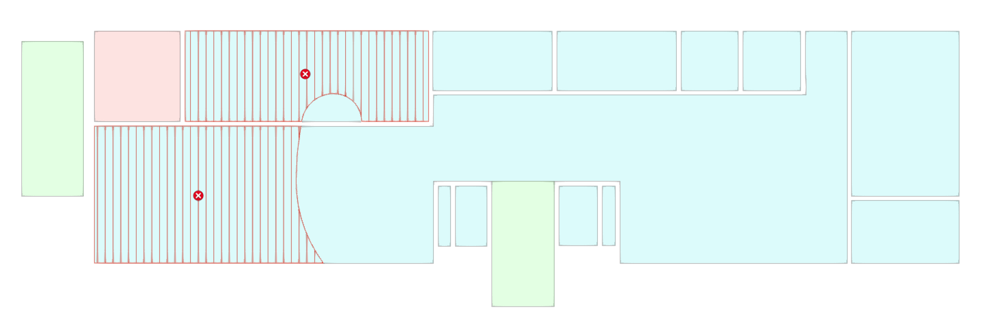
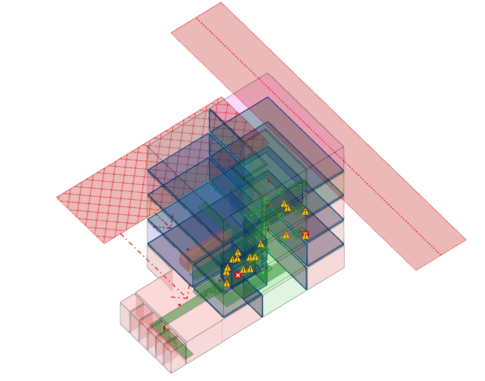
Show/Hide incidents
When this option is activated, the elements that have produced a warning or error are highlighted using an incident system. Hovering the cursor over each incident displays the warning or error message.
Results output
The program obtains the documents for justifying the fire protection systems and exports them to the BIM project on the BIMserver.center platform to which the job is connected.
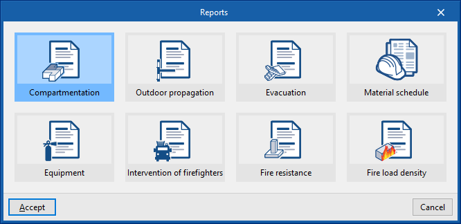
Job reports
The program can also print the following job reports directly or generate HTML, PDF, TXT, RTF or DOCX files:
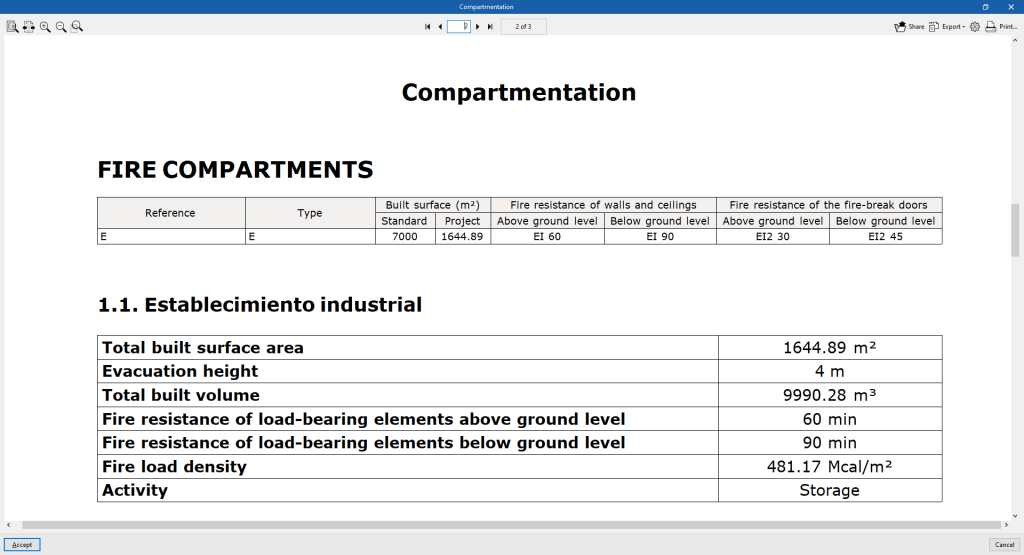
- Compartmentation
Displays information on the interior compartmentation of the building. - Outdoor propagation
Displays the information related to the considered cases of outdoor propagation. - Evacuation
Displays the calculation of occupation, exits and evacuation routes, as well as the parameters related to the design and protection of stairways. - Material schedule
Displays a series of quantities tables of the different materials and equipment in the job, sorted according to their type. - Equipment
Displays the provision of fire protection installations in the fire sectors. - Intervention of firefighters
Displays compliance with the conditions of the building environment and the approach to the building in case of firefighter intervention. - Fire resistance
Displays the fire resistance of walls and ceilings above and below ground level. - Fire load density
Displays the justification of the fire load density, as well as the calculation expressions used and the values of the fuels considered.
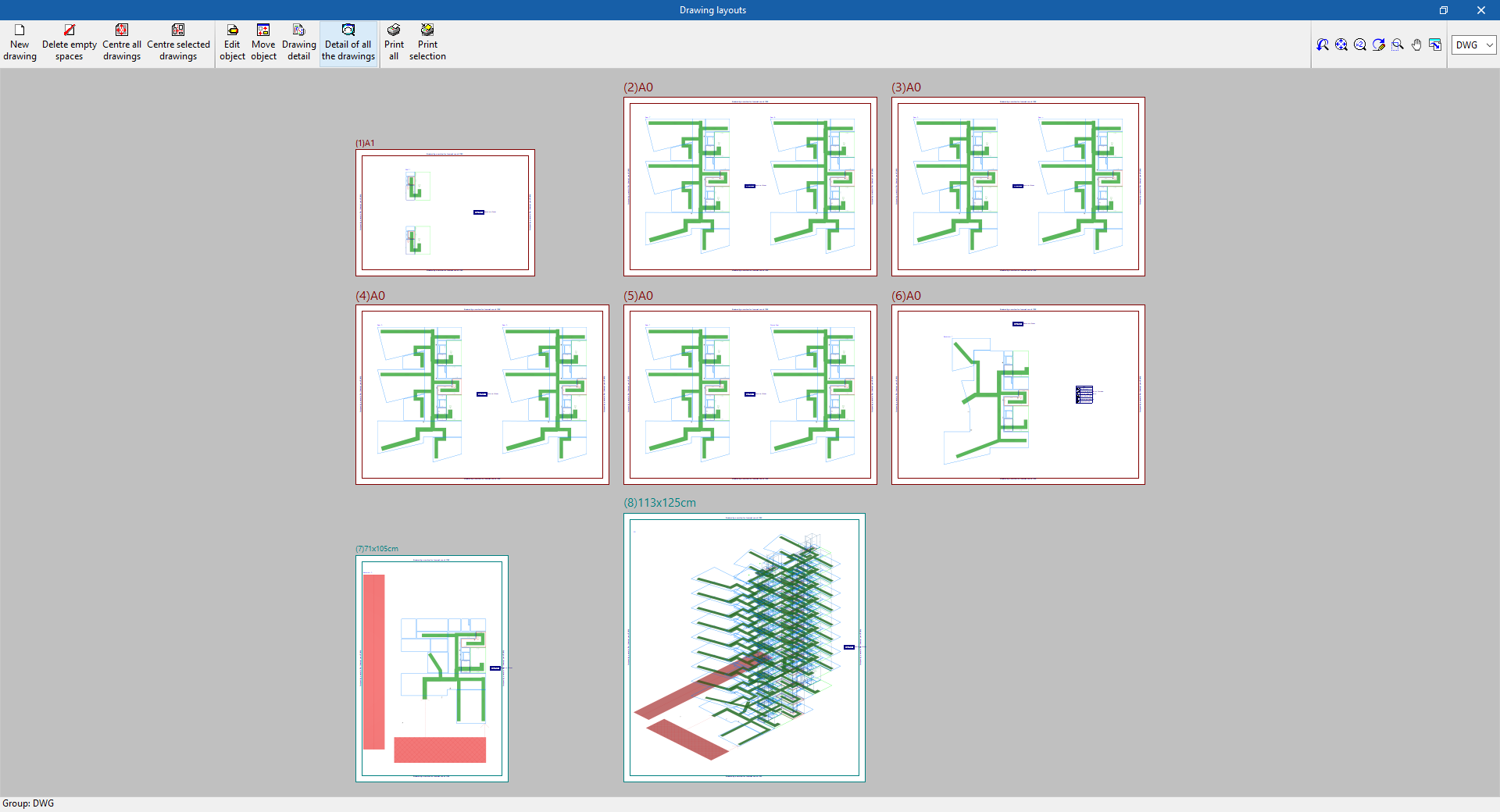
Drawings in DWG, DXF or PDF format
This allows users to print the job drawings on any graphic peripheral that is configured on the computer, or to create DWG, DXF or PDF files.
The following options can be configured when editing the drawing:
- Levels to be drawn (2D or 3D)
- Options
- Generate vector images
- Draw DXF/DWG template
- Include .glTF files in the drawings
- Resolution (96 dpi / 150 dpi / 300 dpi / 600 dpi)
- Scale
- Details
Results in the "Bill of quantities" tab
If the job is completed in the "Bill of quantities" tab, the following documents can be obtained from the program:
- Export of the budget in FIEBDC-3 (BC3) format.
- Bill of quantities reports (in HTML, PDF, TXT, RTF or DOCX format).
Files supported by BIMserver.center
When a project is exported to the BIMserver.center platform, a file in IFC format is automatically exported and, optionally, the bill of quantities reports and checks of the model elements for their integration in the Open BIM project, allowing them to be displayed:
- On the online platform;
- In the BIMserver.center app for iOS and Android.
Integration into the BIMserver.center platform
Many of CYPE's programs are connected to the BIMserver.center platform and allow collaborative work to be carried out via the exchange of files in formats based on open standards.
Please note that, to work on BIMserver.center, users can register on the platform free of charge and create a profile.
When accessing a program connected to the platform, the program connects to a project in BIMserver.center. This way, the files of the projects that have been developed collaboratively in BIMserver.center are kept up to date.

| More information: |
|---|
| For further details related to using CYPE software via the BIMserver.center platform, please click on this link. |
Options available in CYPEFIRE
The "BIMserver.center" group in the main toolbar contains the features required to use CYPEFIRE together with other BIMserver.center tools.

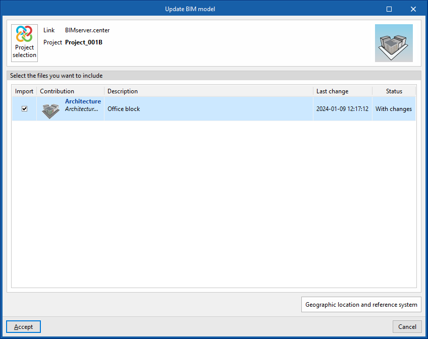
Update
Updates information contained in models previously imported into the project or imports new models if desired.
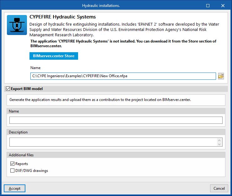
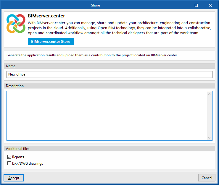
Share
Exports the information of the model developed with CYPEFIRE to BIMserver.center to share it with other users, including its three-dimensional representation, design reports and system drawings.
During the export process, information related to the identification of the files to be exported and the types of files that are generated can be defined:
- Name
- Description
- Additional files
- Reports (optional)
- DXF/DWG drawings (optional)
Direct connection to other programs
CYPEFIRE offers direct connection options with Open BIM tools that allow users to continue their work.
Using these options, the CYPEFIRE BIM model can be sent to:
- CYPEFIRE Hydraulic Systems
- CYPEFIRE Pressure Systems