Steel beams
General features of CYPECAD’s Steel beams module
Data entry
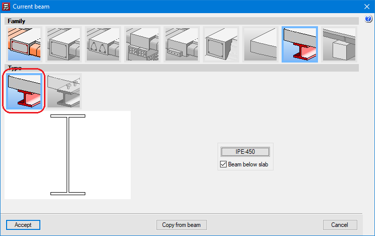
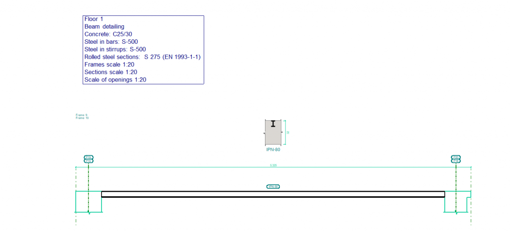
With the Steel beams module, the following types of beams can be entered and designed:
- Steel beams below a floor slab or aligned with its upper face.
- Composite steel beams linked to the floor slab with connectors.
CYPECAD designs concrete beams and foundation beams. This requires either the Concrete beams module or the Floating columns module accordingly. It is also possible to define integrated steel or timber structures and connect them to an element in the entered structure. This requires a license to use CYPE 3D.
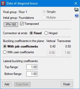
Steel sections are selected from predefined libraries in the program. CYPECAD has 33 different section libraries. Additionally, users can add their own libraries by copying existing ones or manually inserting them. Sections that do not come from a library (editable sections) can also be entered into a job, to do this, users must enter their geometric and mechanical features.
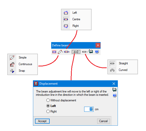
Beams can have a straight or curved directrix and the program allows both to be entered in continuous mode (when the end of a beam is marked, the starting point of the following beam to be entered is also marked), or in simple mode (after marking the final point of a beam, if another beam is to be entered, the starting point of the following beam must be marked once again).
The beams’ faces or axis can be set to a reference point (column axis, ends of beams or element snaps from a drawing file in DXF or DWG format). The selected adjustment (faces or axis of the beam to be entered) can be shifted compared to the reference points.
CYPECAD can also automatically assign a beam outline to a polygonal (either open or closed) in a DWF or DWG file. The axis or faces of the beam can be adjusted to the polygonal, even in a given displacement. Another CYPECAD feature allows the program to automatically enter the beams of the floor slabs considering the guidelines indicated by the user and the directrixes of each floor present in drawing templates in DXF or DWG format. Both features are part of the Automatic entry module.
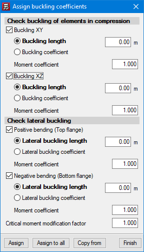
The program contains tools that allow users to define the interaction of beams with the rest of the structure’s elements. Users can also pin beams at any of their ends, modify the fixity coefficient of the beam’s faces, manage alignment generation (consecutive beam spans that the program considers to be a single frame), divide or join alignments, enter a beam that covers two floors, etc. Additionally, the check of lateral buckling can optionally be carried out.
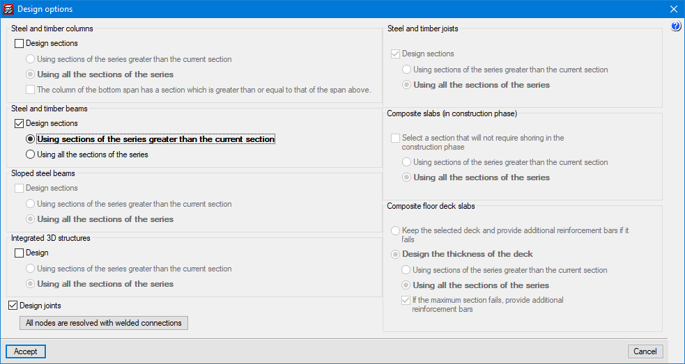
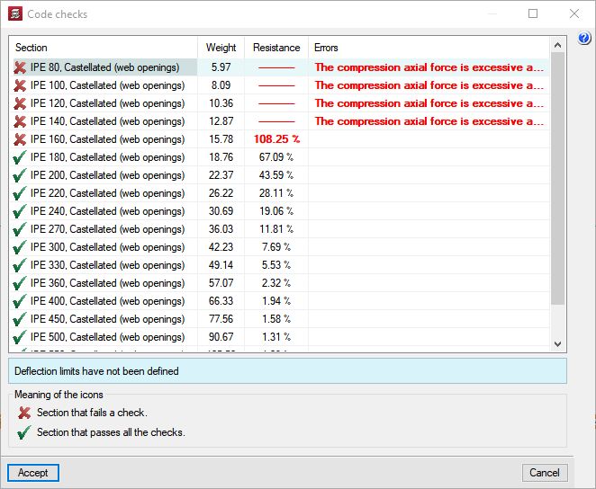
Before the analysis, the program requires the user to select the design options for the project’s composite and steel elements. For steel beams, users can decide whether to have them designed by the program or to keep the ones they have specified themselves. When users want the program to design them, they can choose between two options: that the program only uses section series greater than the one provided by the user or that it can even use lower sections as long as they comply with the user’s specifications.
Results analysis
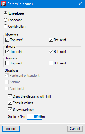
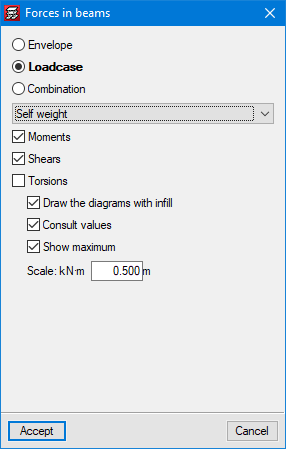
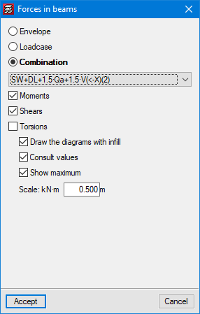
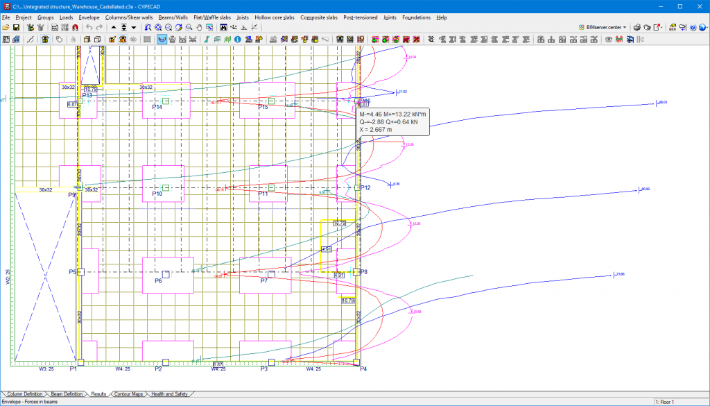
CYPECAD has results analysis tools such as graphical representations with numerical values of envelope forces (moments, shear and torsion), forces for simple loadcases and forces for the desired loadcase combination.
The program also analyses beam deflection and warns users if any beams exceed the limits established in the program according to the selected code. Users can modify these deflection limits.
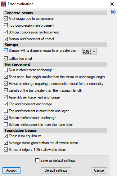
After the analysis, CYPECAD marks any beams displaying errors with two colours. Depending on the selected code, the program classifies the errors according to their importance. Users may alter this classification according to their own criteria. The meaning of each error is explained via the help functions within the program.
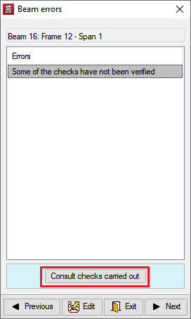
Beams marked with errors can be selected for the program to report these problems.
Detailed ultimate limit state check reports for steel beams
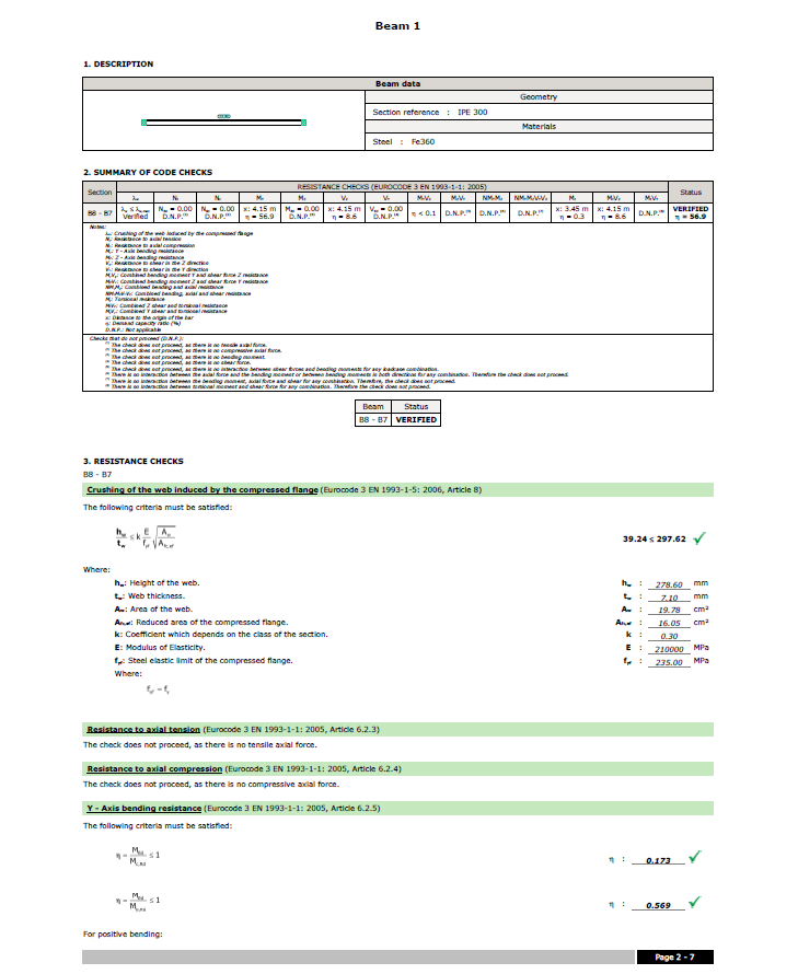
CYPECAD generates detailed ultimate limit state check reports for rolled, reinforced and cold-formed steel beams. The U.L.S reports contain all the checks carried out by the program for designing steel beams. Each check refers to the codes and the article required, or to the criteria considered in order to verify it. The details in the U.L.S. reports make them essential documents with which users can verify, justify and optimise the design of the structural elements analysed.
The level of detail in these reports also gives them a didactic purpose, allowing users to learn about all the checks that a section is subject to.
More information on these documents (CYPE programs that generate U.L.S reports, ways to obtain them, codes for which they can be generated, etc.) can be found at Detailed ultimate limit state check reports.


