Loads
In addition to self-weight loads, the program generates the following loads:
Soil pressures
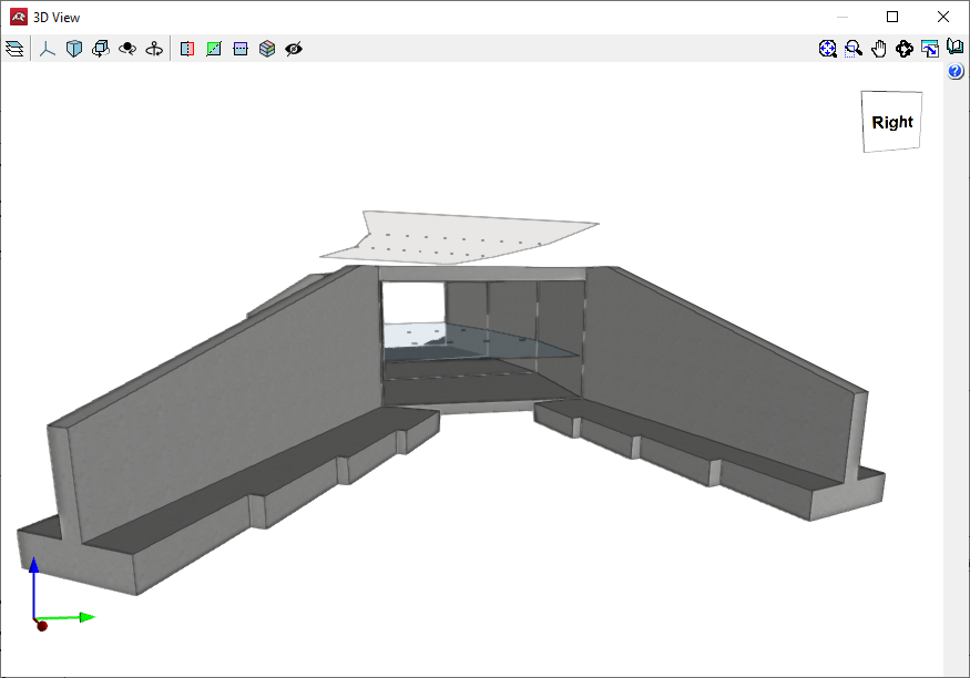
This includes all the actions caused by the soil on the elements of the structure in contact with it. The action of the soil has two components: the weight on horizontal elements (frame lintel, heel of the wing walls) and the thrust on vertical elements (module lateral walls, wing walls).
- The weight of the soil on the horizontal elements is determined by applying the specific weight of the backfill poured and compacted to the volume of soil gravitating on the surface of the horizontal element.
- The estimation of the horizontal pressures is carried out by a two-dimensional analysis, entering sections perpendicular to the walls of the module and the wing walls. The lateral walls of the module are considered to be rigid enough to be able to consider a state of the stress of earth pressure at rest.
The earth pressure at rest coefficient is estimated through the use of Jaky’s formula. If there is a certain slope angle, the additional formulation from the Corps of Engineers, 1961, is applied.
For wingwalls, the pressure of the wingwall on the wall is calculated using the Coulomb method (active pressure coefficient method), considering a slope angle equal to the internal friction coefficient. The slope ends at the level of the top road surface; from this point onward, the soil is considered to be horizontal. The model can consider the cohesion effects and the friction angle between the soil and the wall.
Loads applied on the top road surface
The program defines the variable service and/or exploitation loads applied on the road surface:
Top surcharge
Infinite-extension superficial dead load. Different dead loads can be defined for the modules and each of the wingwalls. Combinations are considered as incompatible with other loads applied on the road surface.
Strip loads
Used to simulate corresponding traffic surcharges on the roadway. Their effect on the wingwalls is not considered.
Truck loads
The available truck loads are described in the Spanish IAP-98, Portuguese RSA, Brazilian NBR, French CBC, Eurocode, and ROM 0.2-90 standards. Additionally, users can define their own truck loads. Their effect on the wingwalls is not considered.
All of these loads are considered to be applied in the Z global direction and only affect the module.
These loads may act on the structure in different ways:
- Effect on the lintel: The loads transfer their action onto the lintel through the fill, which behaves as a distribution layer that projects the load enclosure as a pyramid. The transmission angle can be configured by the user. The surface value of the projected load is determined with the condition that the point value is the same as in the original load.
If no fill is defined or the thickness of the layer is null, the load will be considered as directly applied to the lintel. - Effect on the lateral walls: The loads transfer their action onto the module’s lateral walls through the fill, so that the earth generates additional pressure on them. The loadcase of an at-rest earth pressure state is still valid.
If the load is uniform, the effect of an earth pressure increase is equal to the one caused by the additional height of the earth, of value q 1/(g cos(b)), where b is the slope angle, q is the load value, and the specific weight of the soil.
The effect of point load rigid walls, with prevented displacement, is determined by using elasticity theory. The problem is solved using the Boussinesq approximation, replacing the condition of no wall deformation, with an additional virtual load symmetrical to the real one, with respect to the wall’s backfill.
If the applied action is a strip load or truck load, they are calculated by point load superposition.
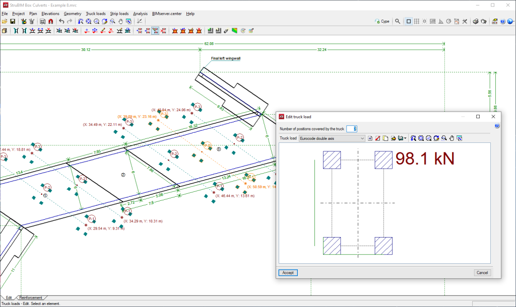
Truck loads can be entered from those available in different codes and in a wide library of vehicles. They can be entered in any position, graphically indicating the axis path and the distance between the sequence of truck positions, strip loads, loads on slabs, etc.
Adds, deletes, duplicates and edits truck loads, and selects a truck load from the existing ones in the libraries.
Loads applied on the bottom slab
Bottom uniform load: Superficial load applied exclusively on the bottom slab of the module.
Hydraulic surcharge
Load caused by a water flow inside the frame. This is evaluated based on a specific weight of water equal to 9.8 kN/m3 . The water pressure is hydrostatic. As for combinations, they are considered incompatible with the bottom uniform load.
Loads of hydraulic origin acting on the screed and inner walls of a single or multi-module frame can be entered.


