Work environment
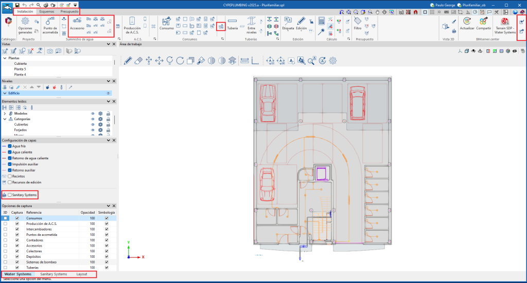
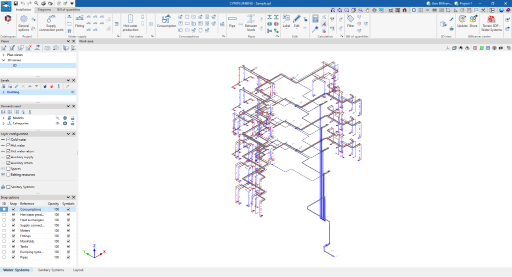
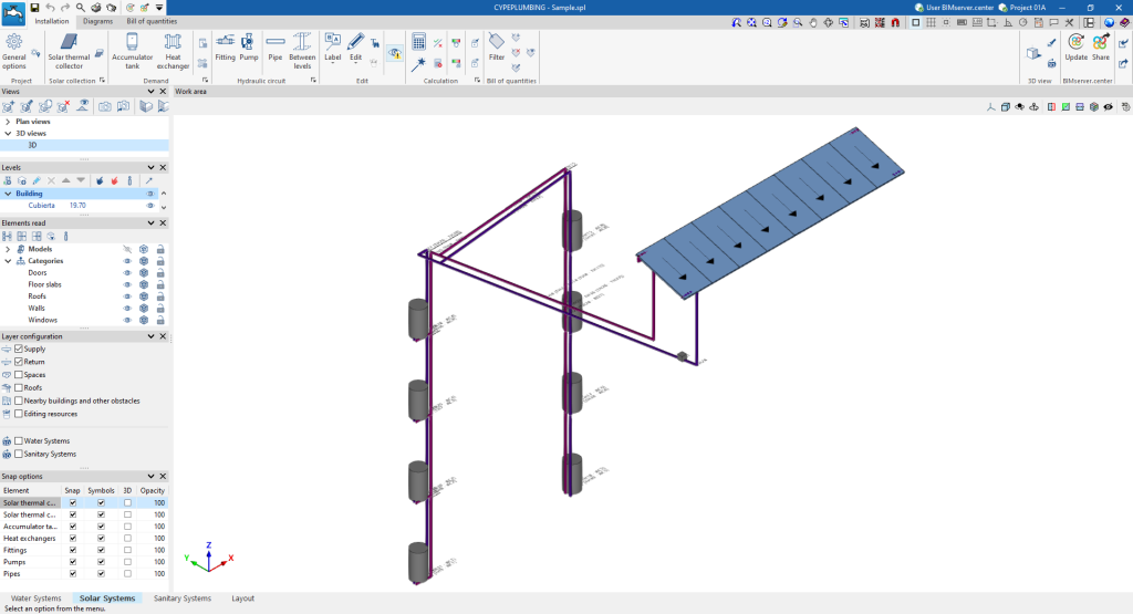
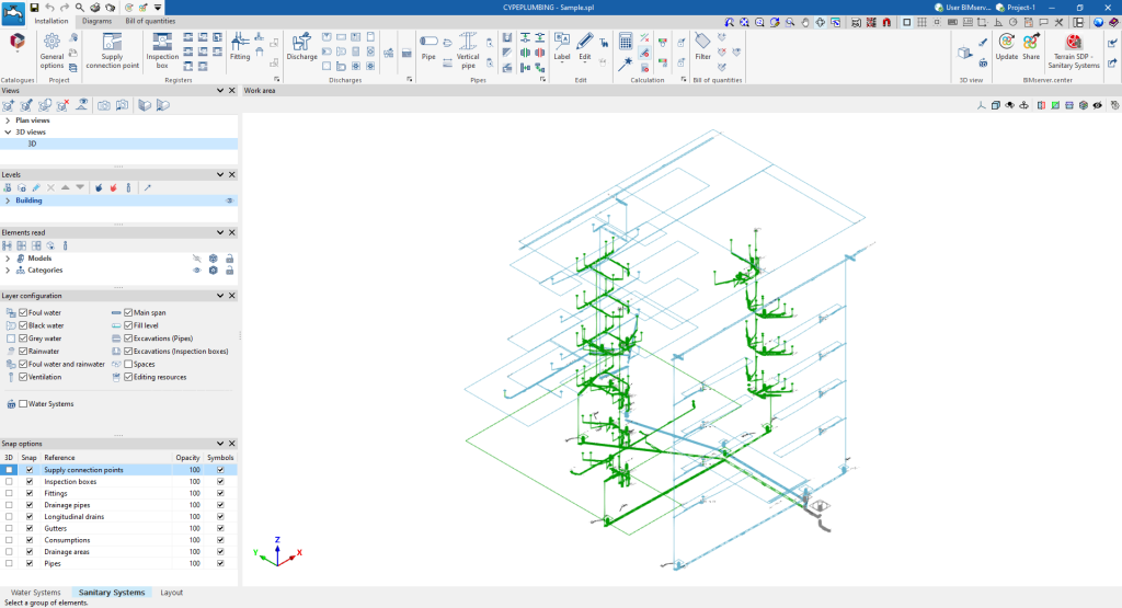
The CYPEPLUMBING interface has four tabs at the bottom of the main window with different work environments: "Water Systems", "Solar Systems", "Sanitary Systems" and "Layout". These environments are similar to those in other CYPE tools and have a system of dockable windows that can be customised to adapt the workspace to the project's needs.
"Water Systems" tab
The "Water Systems" tab contains the tools for entering and designing water supply systems.
This tab is also sorted into three other tabs located at the top of the main window:
- Installation
- Diagrams
- Bill of quantities
When an element with an associated consumption and discharge is entered in the "Water Systems" tab, the discharge is automatically included in the "Sanitary Systems" tab.
More information on these options and features can be found on the CYPEPLUMBING. "Water Systems" tab detailed information page.
"Solar Systems" tab
The "Solar Systems" tab contains the tools for entering and designing solar thermal systems.
This tab is also sorted into three other tabs located at the top of the main window:
- Installation
- Diagrams
- Bill of quantities
More information on these options and features can be found on the detailed information CYPEPLUMBING "Solar Systems" tab page:
"Sanitary Systems" tab
The "Sanitary Systems" tab contains the tools for entering and designing wastewater and rainwater disposal systems.
This tab is also sorted into three other tabs located at the top of the main window:
- Installation
- Diagrams
- Bill of quantities
When an element with an associated consumption and discharge is entered in the "Sanitary Systems" tab, the consumption is automatically included in the "Water Systems" tab.
More information on these options and features can be found on the CYPEPLUMBING. "Sanitary Systems" tab detailed information page.
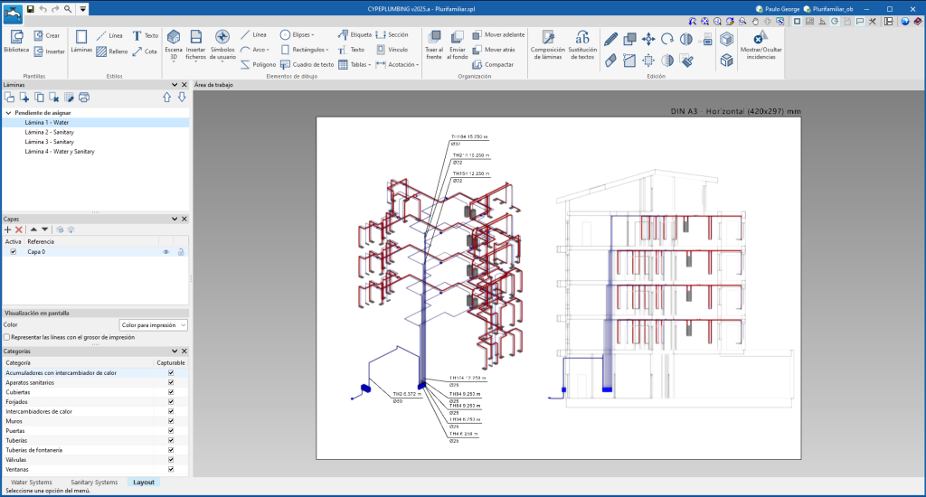
"Layout" tab
In this tab, users can create drawings made up of the two systems (water supply and water drainage) including the graphic information imported from other applications. It is also possible to assign specific tags for water supply and drainage and place them together with the tags so that users can create a 3D view of the plan.

