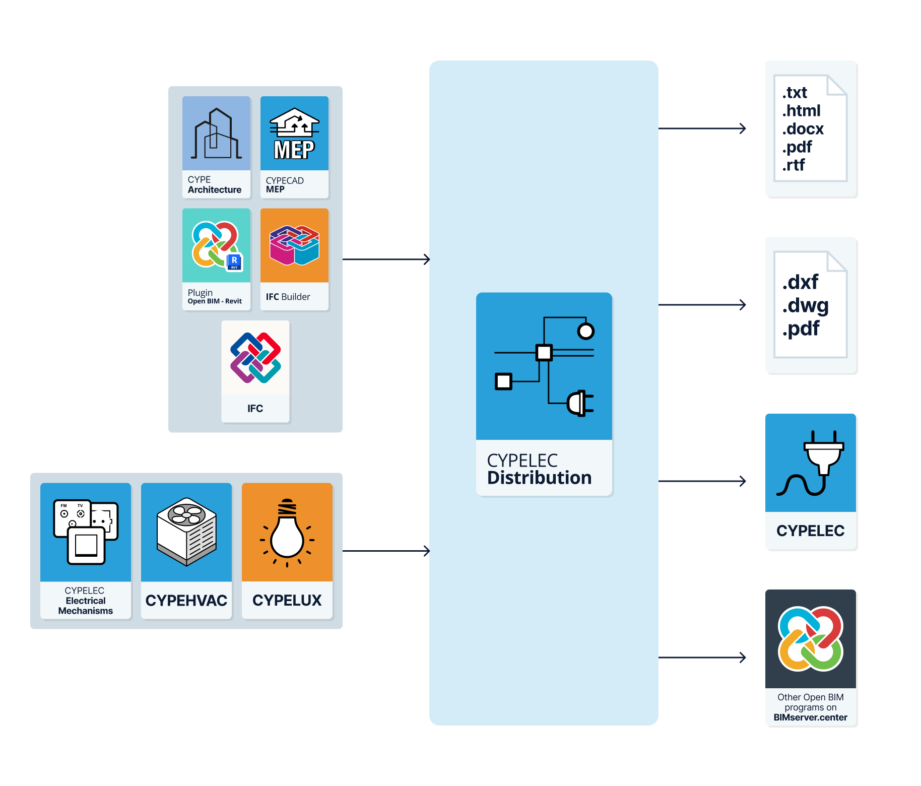
Workflows supported by the program
As an Open BIM tool connected to the BIMserver.center platform, CYPELEC Distribution offers different workflow options.
Data entry
Free modelling / with templates
- Defining the elements of the system by freely entering them in CYPELEC Distribution.
- Defining the elements of the system in CYPELEC Distribution based on DXF/DWG, DWF or image templates (.jpeg, .jpg, .bmp, .wmf).
Importing BIM models
If the CYPELEC Distribution job is linked to a BIM project on the BIMserver.center platform, the following actions can be carried out:
- Importing the model with the geometry of a building. This allows users to generate the floor plan of the building and to insert the elements of the system based on this geometry:
- Importing models designed in CYPE Architecture.
- Importing models designed in IFC Builder.
- Importing models in IFC format with IFC Uploader (generated by CAD/BIM programs such as Allplan, Archicad and others).
- Importing models designed in Autodesk Revit with the Open BIM - Revit Plugin.
- Importing the location of the electrical mechanisms and light points from CYPELEC Electrical Mechanisms, allowing the automatic assignment of receivers to their position. The symbols used in CYPELEC Electrical Mechanisms are also imported and displayed, transferred as a template in DWG format (which can be deactivated in the "Template views manager").
Data output
- Exporting reports to HTML, DOCX, PDF, RTF and TXT formats.
- Exporting drawings to DXF, DWG and PDF formats.
- Exporting information generated with CYPELEC Distribution to the BIMserver.center platform. This allows users authorised to participate in the project to view it and export the distribution of electrical panel and subpanel circuits to programs such as CYPELEC Core, CYPELEC REBT, CYPELEC RETIE or CYPELEC NF for analysing low-voltage electrical systems.
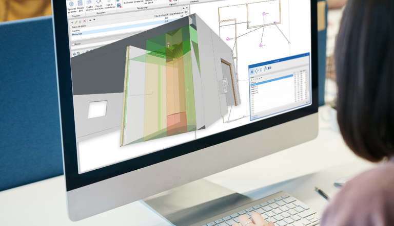
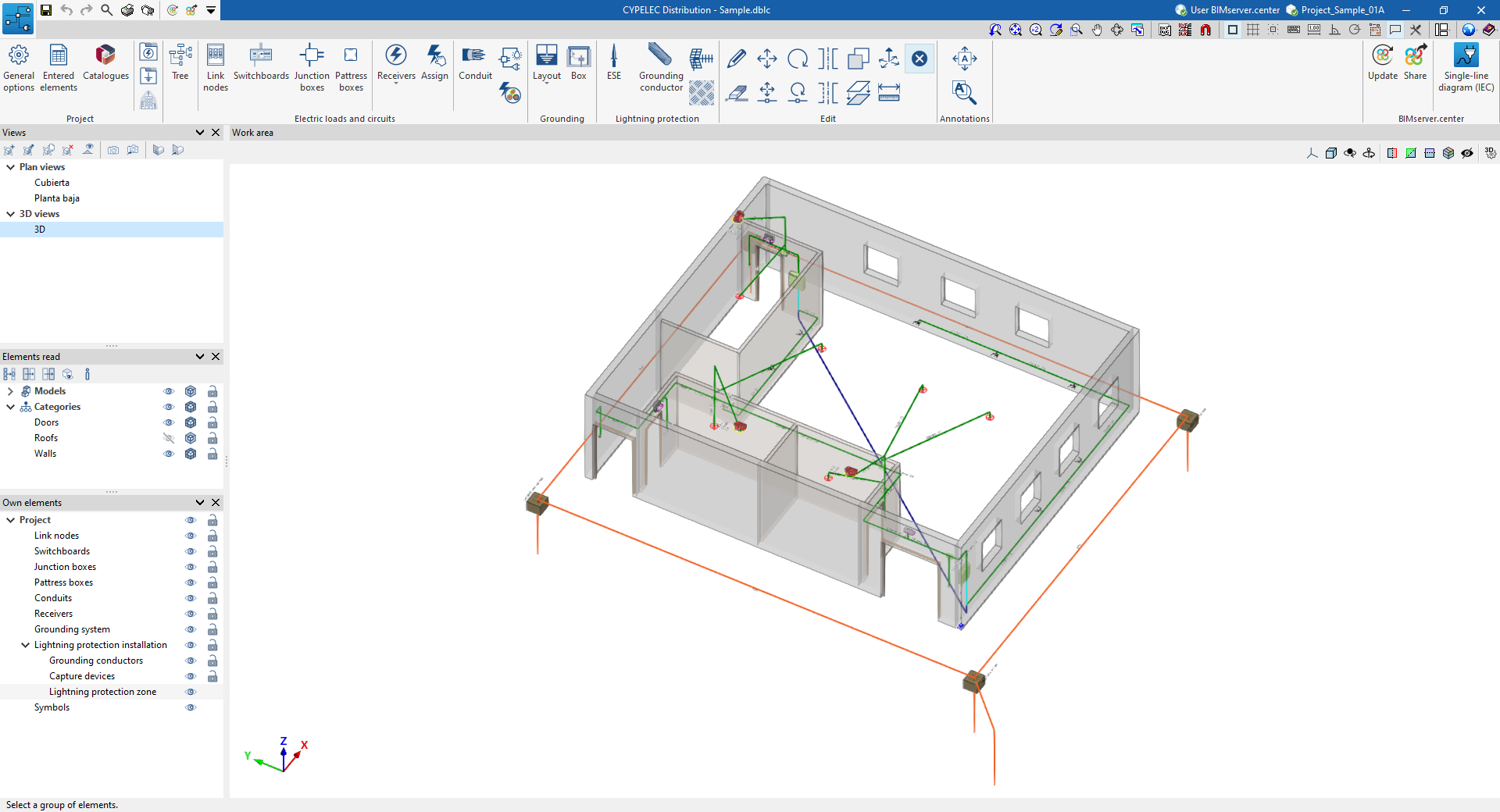
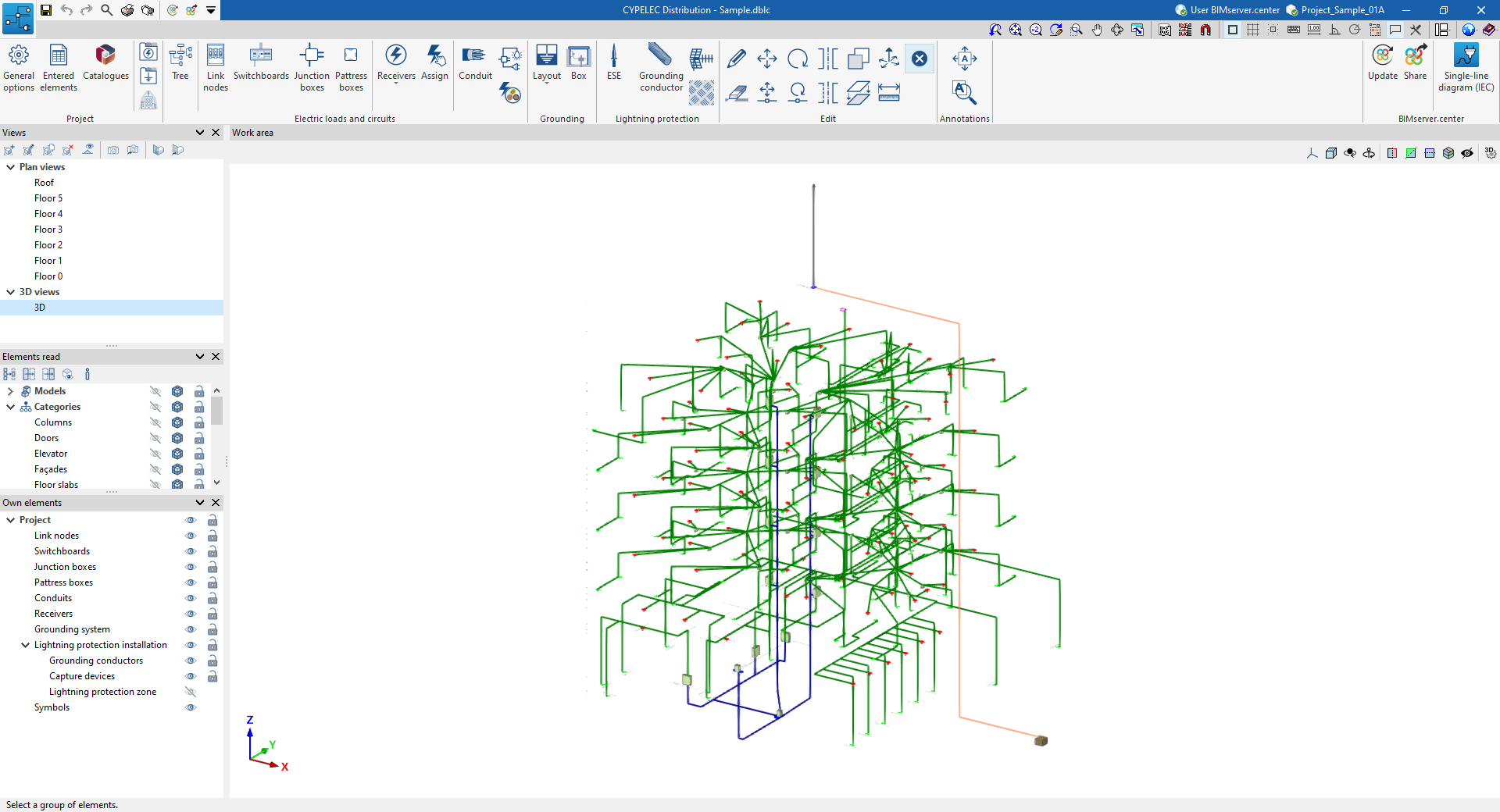
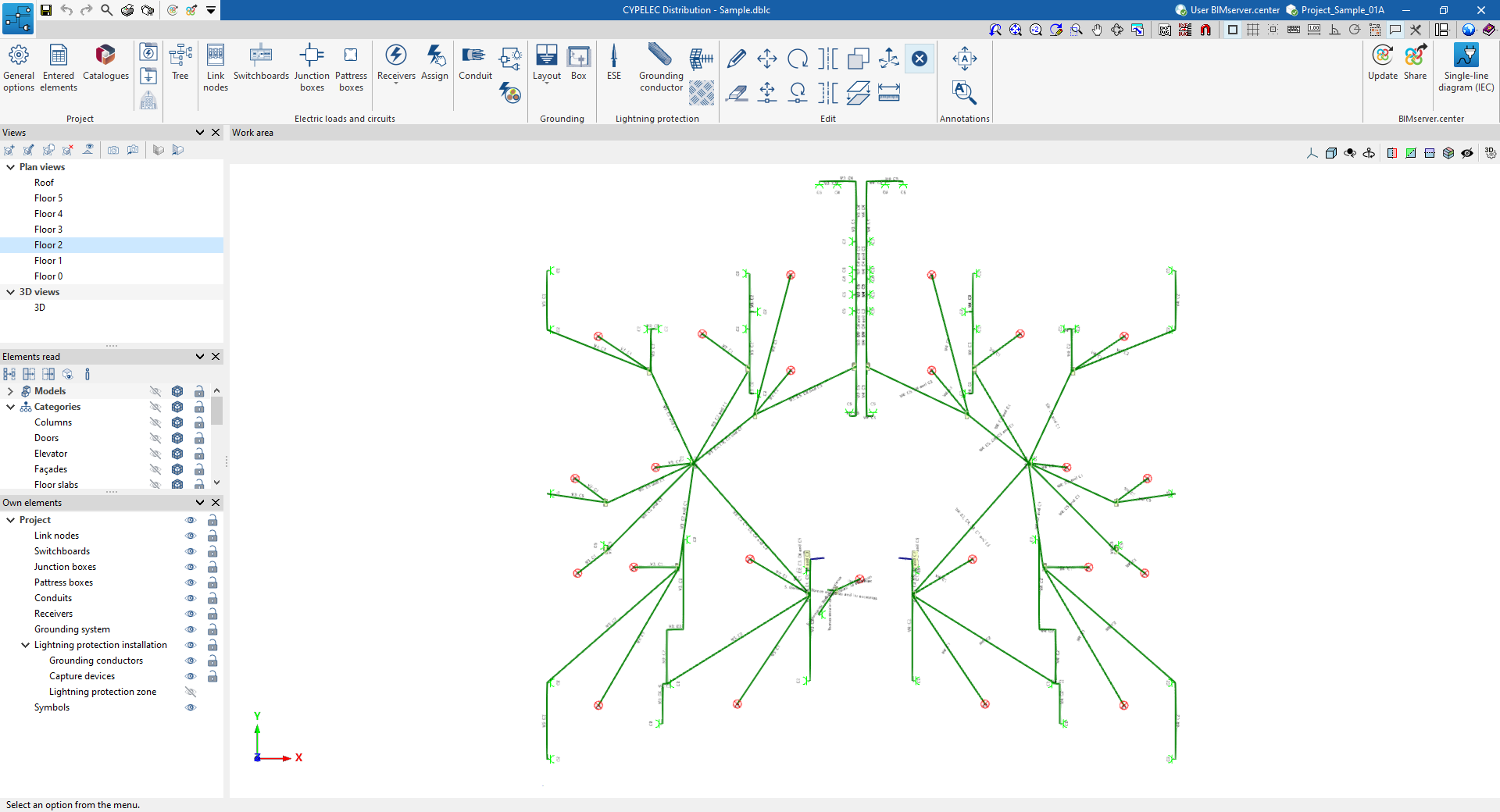
Work environment
The CYPELEC Distribution interface is similar to other CYPE tools and features a system of dockable windows that can be customised to adapt the workspace to the project's needs.
The interface has a work environment that allows the system design to be carried out quickly and easily, both in a 3D view and in any type of 2D view (such as floor plans and elevations). This way, the system elements can be entered using the most appropriate view at any given time.
The interface displays the following:
- A top toolbar where there are tools for managing the project options, entering and editing the elements in the system;
- The modelling area on the right-hand side of the screen, where all the elements of the project are entered, edited and displayed;
- And several panels with tools for defining project views and managing the visibility of the elements read and own elements, on the left-hand side.
Data input and output sequence for the implementation of circuit and load distribution in electrical systems
The implementation of circuit and load distribution in electrical systems can be carried out in the program by means of the following input and output sequence:
- Creating a new job (from "File", "New").
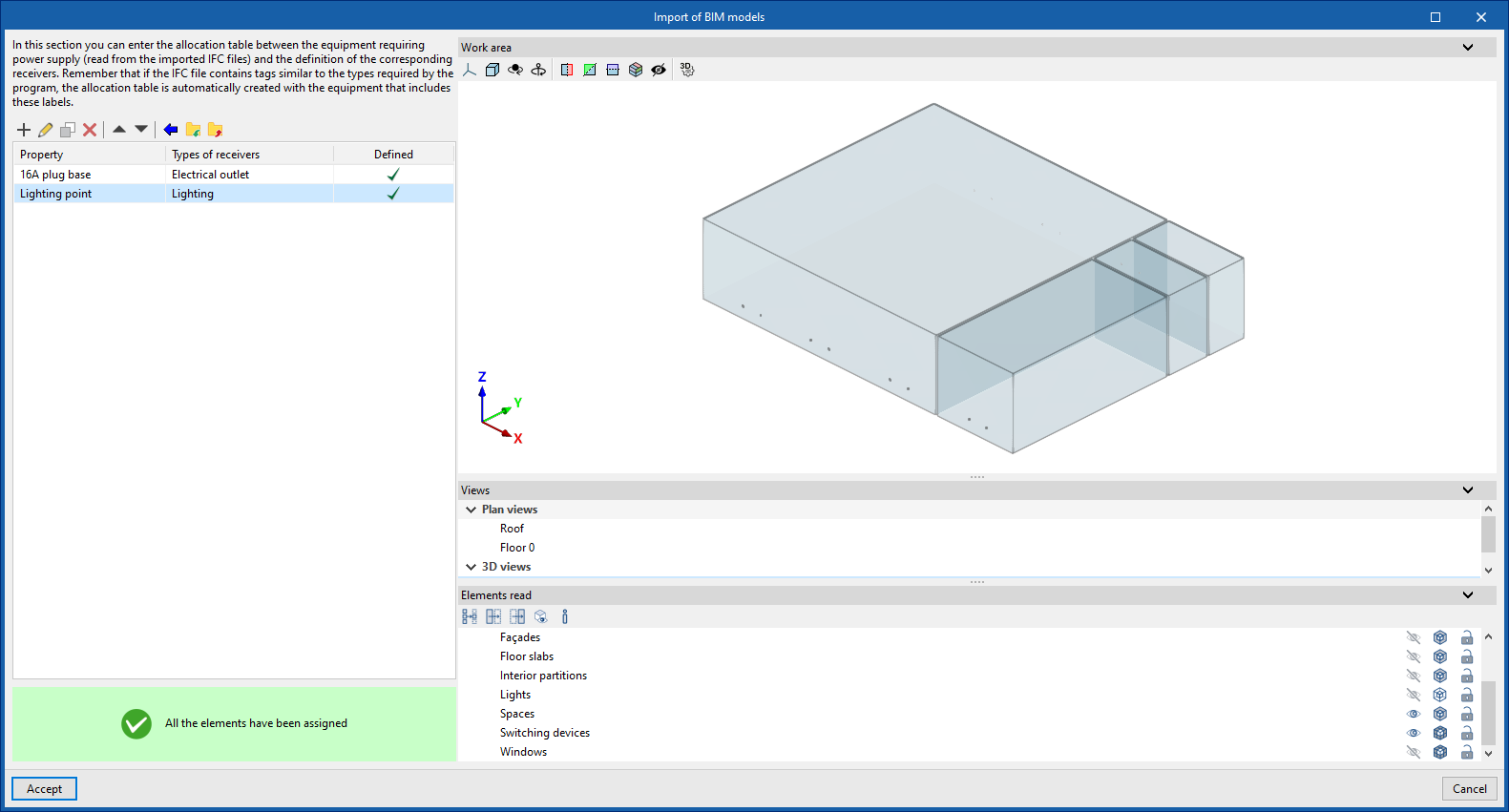
- (Optional) Linking to BIMserver.center, creating receiver types and assigning to equipment requiring power supply read from the BIM model.
- Revising and configuring general options (from "Project", "General options"), including the selection of the standard specifications and the definition of the link node types.
- (Optional) Downloading manufacturer's catalogues (from "Project", "Catalogues").
- (Optional) If not done at the time of creating the job, defining the list of available receiver types (from "Project", "Receiver types").
- (Optional) Defining the list of available grounding systems (from “Project”, “Grounding systems”) in case a grounding system is to be installed.
- (Optional) To install the lightning protection system, the protection level can be defined (from "Project", "Protection level").
- Receiver layout. The receivers are placed in the "Work area" in two ways:
- By importing them through the wizard when creating or updating the work from the loads and equipment read from the BIM project.
- By entering them freely using the "Receivers" option ("Electric loads and circuits" group).
- Panel layout. When creating the "Panels" ("Electric loads and circuits" group) of the installation, the electrical "Circuits" that feed each of the receivers are defined, in addition to the "Feeder (upstream)", whether it is another panel or a node of the feeder.
- Assigning properties to the receivers. After creating the panels and circuits, they are assigned to the receivers by editing them or using the "Assign" tool ("Electric loads and circuits" group).
- Entering conduits. When entering the "Trunking" ("Electric loads and circuits" group), users define the element to be fed, in the case of switchboards or junctions, and the "Circuits" arranged in the trunking. Then, they are drawn by connecting the different elements.
- (Optional) Entering junction boxes and switch boxes. The distribution can be detailed by entering “Junction boxes” and “Switch boxes”, which can be connected to the rest of the installation by means of “Trunking” (options in the "Electric loads and circuits" group).
- (Optional) Generation of branches and conductors. As additional tools in the "Electric loads and circuits" group, the program has several automatisms:
- “Generate branches": generates the routing of conduits between a junction box and the selected receivers.
- “Generate conductors": identifies and generates the circuits inside each trunking, and the junction boxes or nodes it feeds, depending on the distribution entered.
- (Optional) Entering the feeder. The model can be completed by entering the feeder. To do so:
- The layout of the “Link nodes” ("Electric loads and circuits" group), such as the protection boxes and the meter centralisation, is indicated.
- These elements are then connected to each other and to the switchboards using “Trunking” ("Electric loads and circuits" group).
- (Optional) Entering the elements of the grounding system in the model ("Grounding" group).
- (Optional) Entering the elements of the lightning protection system in the model ("Lightning protection" group).
- Obtaining reports and drawings (from "File", "Reports/Drawings").
- Exporting to BIMserver.center (from "BIMserver.center", "Share").
Entering link nodes, switchboards, junction boxes and pattress boxes
In the "Electric loads and circuits" group of the main toolbar users can define and enter link nodes, switchboards, junction boxes and pattress boxes:

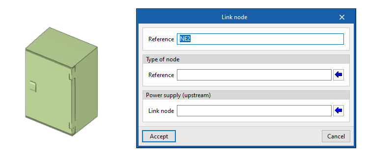
Link nodes
Enters a link node in the model after specifying the following parameters:
- Reference
Reference of the link node. - Type of node
Selects one of the "Link node types" defined from "General options". - Supply (upstream)
Selects the upstream switchboard or link node.
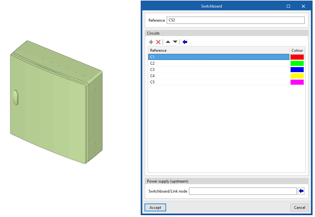
Switchboards
Enters a switchboard or sub-switchboard in the model after specifying the following parameters:
- Reference
Reference of the junction box. - Circuits
Defines the list of circuits assigned to the switchboard or sub-switchboard. The following information is entered in each of them:- Reference
- Colour
- Supply (upstream)
Selects the upstream switchboard or link node.
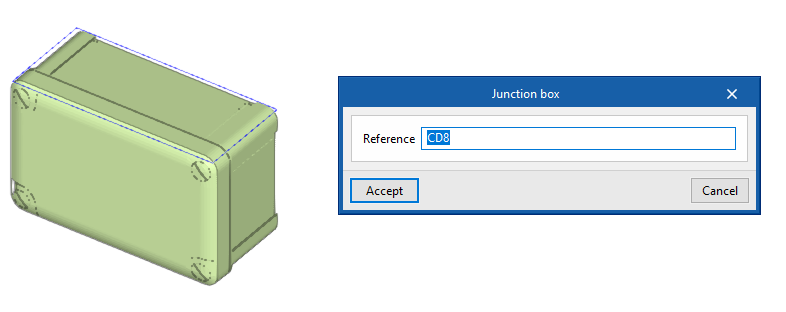
Junction boxes
Enters a junction box in the model after specifying the following parameter:
- Reference
Reference of the junction box.
It is then possible to automatically route the conduits from a junction box to the selected receivers with the "Generate branches" option.
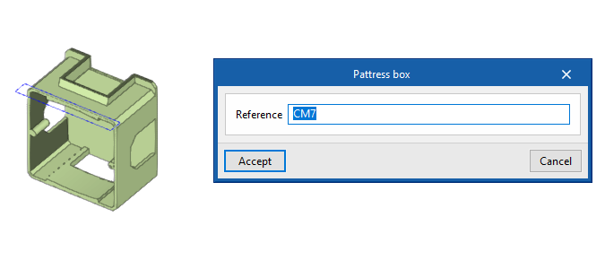
Pattress boxes
Enters a pattress box in the model after specifying the following parameter:
- Reference
Reference of the pattress box.
Entering and assigning receivers
The "Electric loads and circuits" group in the main toolbar contains the tools for entering and assigning receivers:

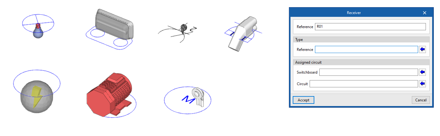
Receivers
Freely inserts receivers into the model.
First, the options displayed in the menu can be used to select the type of receiver from among the following:
- Lighting
- Emergency
- Electrical outlet
- Motor
- Lifting device
- Electric vehicle recharging
- Generic
The following parameters must then be entered, which indicate the reference and type of receiver, as well as the switchboard and circuit it belongs to:
- Reference
Receiver reference. - Type of receiver
Selects one of the types of receivers created from the corresponding option in the "Project" group. - Switchboard
Selects one of the previously entered switchboards. - Circuit
Selects one of the circuits associated with the switchboard indicated in the previous field.
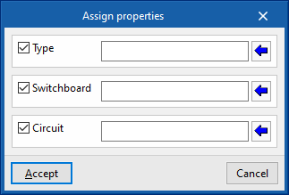
Assign
Assigns the following properties to the selected receivers:
- Type of receiver (optional)
Selects one of the types of receivers created from the corresponding option in the "Project" group. - Switchboard (optional)
Selects one of the previously entered switchboards. - Circuit (optional)
Selects one of the circuits associated with the switchboard indicated in the previous field.
This option allows mass modification of the properties of the desired receivers without the need to edit them one by one.
Designing a lightning protection system
In the "Lightning protection" group of the main toolbar, there are options for designing a lightning protection system using a lightning protection device with an early streamer emission lightning conductor:

The following options are available:
- ESE
- Lightning rod
- Rolling sphere
- Lightning mesh
- Add opening in lightning rod
- Delete opening in lightning rod
- Conductor
- Vertical conductor
- Test link box
- Antenna
- Metallic element
- Automatic generation of lightning meshes
- Linear distribution of lightning rods
- Join
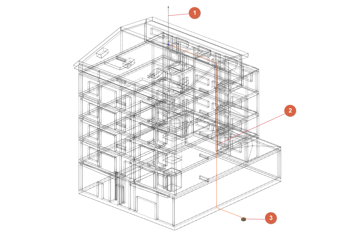
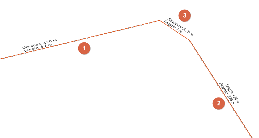
The lightning conductor system may consist of the following elements:
- An early streamer emission lightning conductor (1); alternatively, lightning rods and meshes (connected with a conductor) may be used. Optionally, antennas or receiver assemblies and/or steel elements susceptible to atmospheric electrical discharges may be provided.
- One or more down conductors (2) connecting the early streamer emission lightning conductor (or lightning rods and meshes), antennas and steel elements to the grounding system.
- One or more chambers (3) of the ground connection (entered from the "Inspection box" option in the "Grounding" group).
The program will analyse the layout of the conductors and ensure that all elements are connected to the ground connection.
When entering an early streamer emission lightning conductor, lightning rods or meshes, if a "Protection level" has not been defined with the specific option in the "Project" group, the program allows this to be done at that time. The design of the lightning protection system will depend on the protection level assigned to the project.
Each of the above options is detailed below:
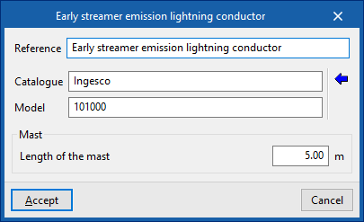
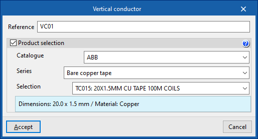
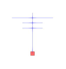
Early streamer emission lightning conductor
Enters an early streamer emission lightning conductor.
Next, the following information must be provided:
- Reference
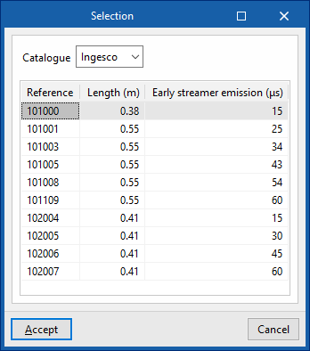
Reference of the early streamer emission lightning conductor. - Catalogue / Series / Selection
The program selects a lightning conductor model from the manufacturer catalogues included in the Open BIM Database. - Mast
- Catalogue/ Selection
The program selects a mast model from the manufacturer catalogues included in the Open BIM Database.
- Catalogue/ Selection
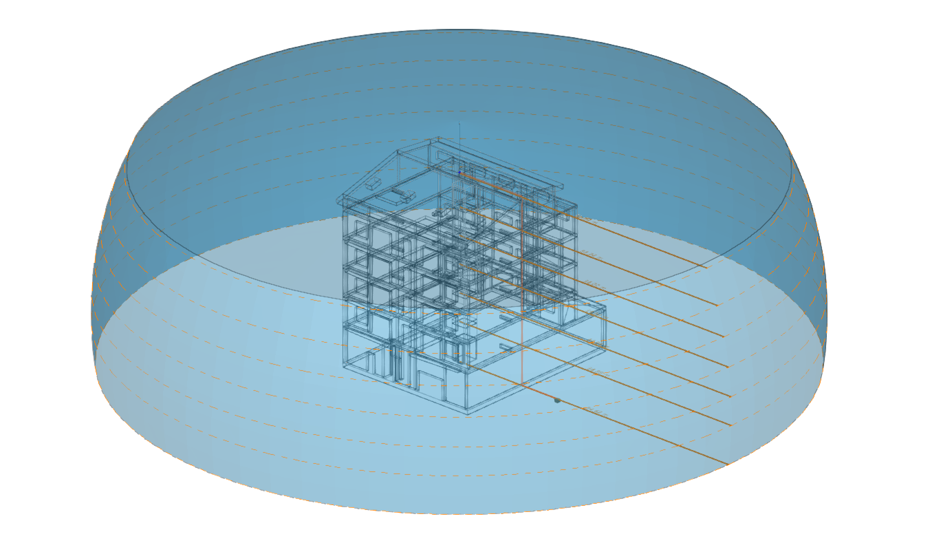
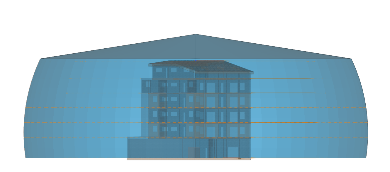
Once the early streamer emission lightning conductor has been entered, the program displays the protected volume and checks whether the volume is sufficient based on the characteristics of the building.
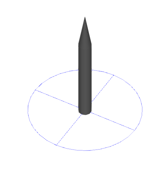
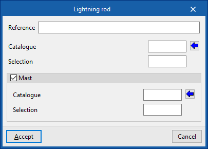
Lightning rod
Enters a lightning rod.
Next, the following information must be provided:
- Reference
Reference of the lightning rod. - Catalogue / Selection
The program selects a lightning conductor model from the manufacturer catalogues included in the Open BIM Database. - Mast (optional)
- Catalogue/ Selection
The program selects a mast model from the manufacturer catalogues included in the Open BIM Database.
- Catalogue/ Selection
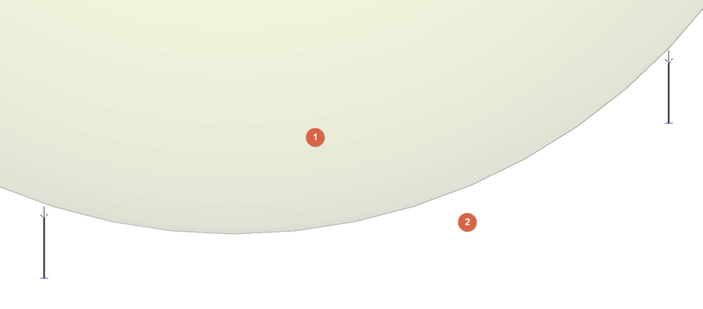
Rolling sphere
Enters a sphere into the model to visually check the effectiveness of the lightning protection system design.
To define this sphere, after entering the "Radius", two upper points of elements such as early streamer emission (ESE) air terminals or lightning rods are selected.
At this point, the sphere will be drawn. The interior of the sphere (1) is considered to be under lightning influence, while the space beneath the sphere (2) is considered protected by the installation.
The user can place different spheres between different pairs of air terminals to check the design of the installation, ensuring that no parts of the building are located inside the sphere
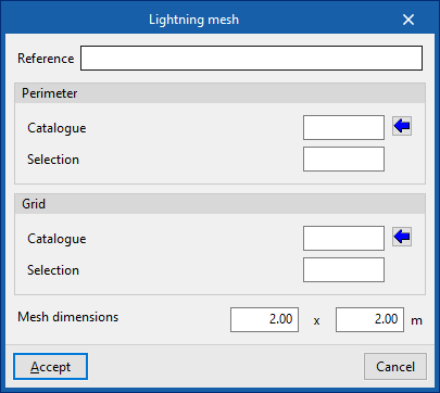
Lightning mesh
Inserts lightning mesh. These elements can be installed on a flat or sloping roof slab.
Next, the following information must be provided:
- Reference
Reference of the lightning mesh. - Perimeter
Defines the perimeter wiring of the mesh.- Catalogue / Selection
The program can be used to select a product from the manufacturer's catalogues included in the Open BIM Database.
- Catalogue / Selection
- Grid
Defines the grid of the internal mesh network.- Catalogue / Selection
The program can be used to select a product from the manufacturer's catalogues included in the Open BIM Database.
- Catalogue / Selection
- Mesh dimensions (a x b)
These dimensions must be smaller than those indicated for the meshes in the "Level of protection" option in the "Project" group.
Adds opening in lightning mesh / Deletes opening in lightning mesh
These options are used to adjust the geometry of the previously entered lightning meshes by adding or deleting openings in them.
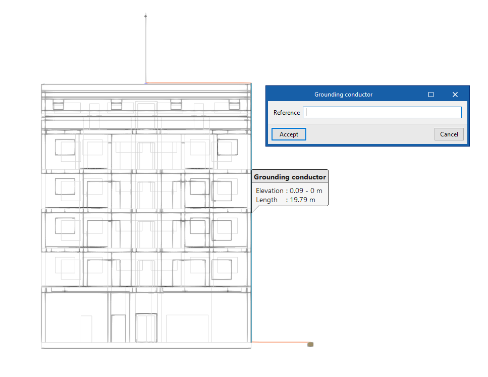
Grounding conductor
Enters the shunts or grounding conductors for the conduction of the atmospheric discharge current from the collector devices to the earth electrode, drawing their layout in the model.
Elements can also be connected to each other, such as a rod with lightning mesh.
This element can be arranged in any direction, either horizontally or vertically.
When entering a grouding conductor, the following data must be entered:
- Reference
Reference of the grounding conductor. - Product selection (optional)
- Catalogue / Selection
The program is used to select conductors from the manufacturer's catalogues included in the Open BIM Database.
- Catalogue / Selection
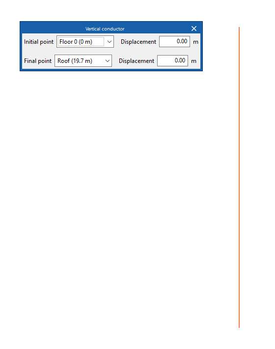
Vertical conductor
Enters vertical conductors between floors.
The definition of the element is identical to that which appears when using the "Conductor" option, but in this case, for its insertion, two floors must be selected as the "Starting point" and "End point" of the conductor. In each of them, a "Displacement" can be applied to adjust the elevation of these starting and end points.
Then, click on a point to mark the position of the element on the plan.
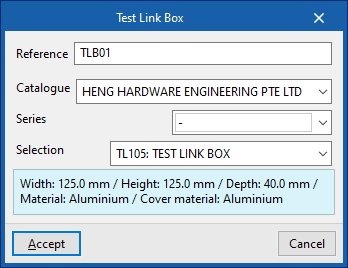
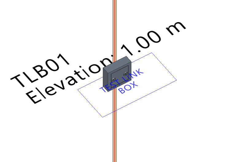
Test link box
Enters a test link box that allows tests to be carried out on the installation. These elements are placed at a certain height, near the lower end of a down conductor in installations with air terminals or mesh conductors.
- Reference
Reference of the test link box. - Catalogue / Series / Selection
The program allows the selection of connection boxes for testing from the manufacturer catalogues included in the Open BIM Database.
Antenna (receiver group)
Inserts an antenna or a receiver group. These elements may be susceptible to atmospheric electrical discharge.
These elements must be connected with lightning conductors to the rest of the lightning protection system.
Metallic element
Metallic elements such as gutters and metal tanks on the roof, as well as other metallic masses of the building exposed to electric discharge and which do not include their own grounding, can be installed in the model.
These elements must be connected with lightning conductors to the rest of the lightning protection system.
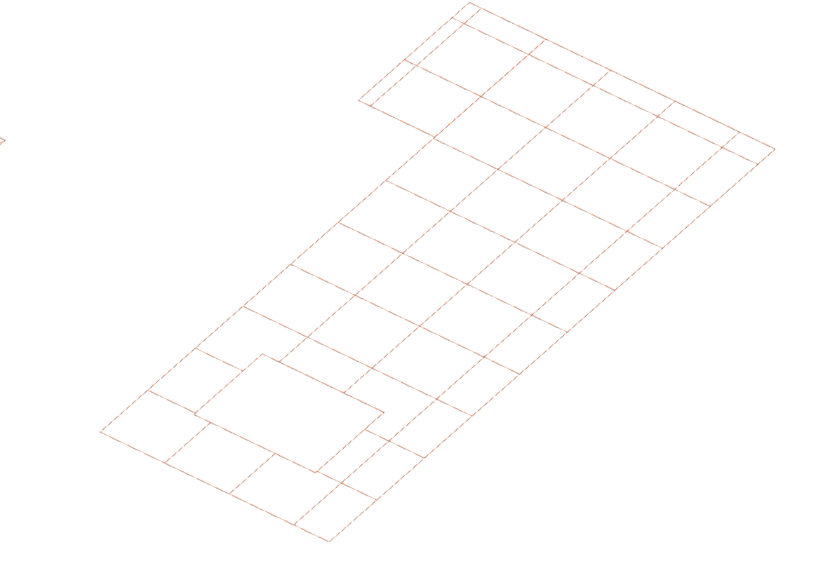
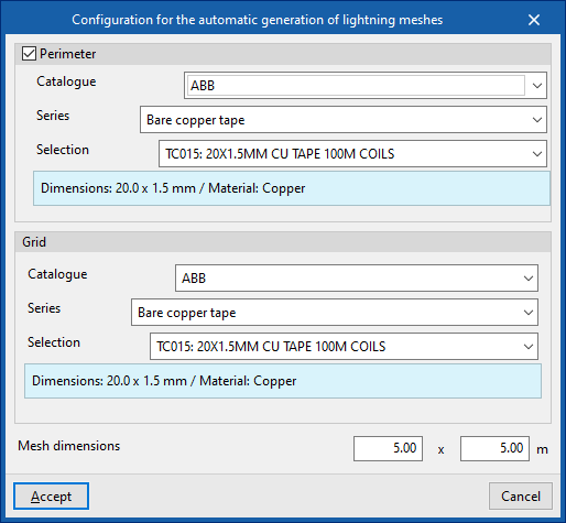
Automatic generation of lightning meshes
Automatically generates mesh conductors on the roofs of the model.
When the option is selected, the "Configuration for the automatic generation of lightning meshes" window opens, where the following data must be specified:
- Perimeter (optional)
Defines the wiring of the mesh perimeter.- Catalogue / Series / Selection
The program allows the selection of a product from the manufacturer catalogues included in the Open BIM Database.
- Catalogue / Series / Selection
- Grid
Defines the wiring of the internal grid network.- Catalogue / Series / Selection
The program allows the selection of a product from the manufacturer catalogues included in the Open BIM Database.
- Catalogue / Series / Selection
- Mesh dimensions (a x b)
These dimensions must be smaller than those indicated for meshes in the "Protection level" option of the "Project" group.
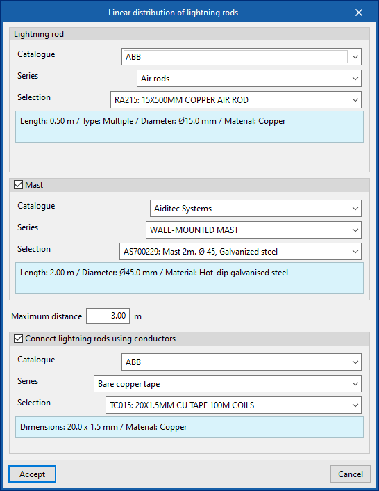
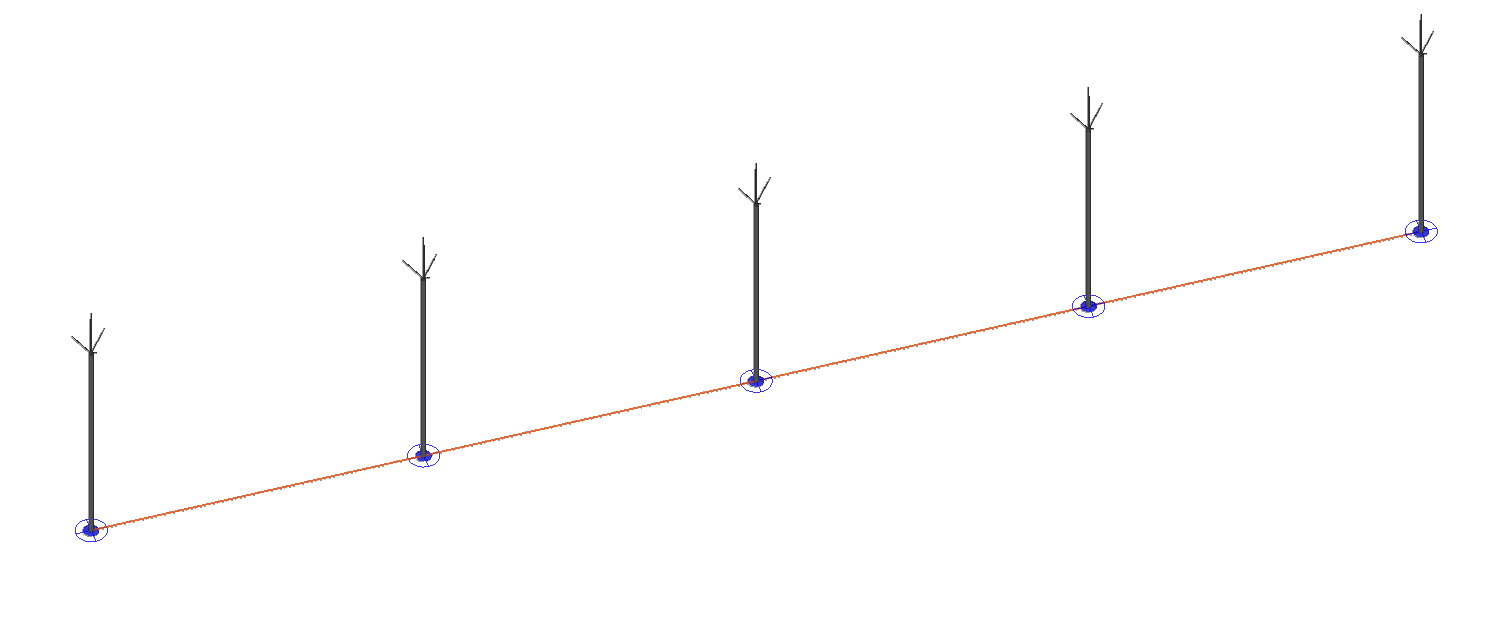
Linear distribution of lightning rods
Allows the generation of a distribution of air terminals connected by conductors along a polyline introduced in the model.
When the option is selected, the "Linear distribution of lightning rods" window opens, where the following data must be specified:
- Lightning rod
- Catalogue / Series / Selection
The program allows the selection of an air terminal model from the manufacturer catalogues included in the Open BIM Database.
- Catalogue / Series / Selection
- Mast (optional)
- Catalogue / Series / Selection
The program allows the selection of a mast model from the manufacturer catalogues included in the Open BIM Database.
- Catalogue / Series / Selection
- Maximum distance
Indicates the maximum distance between the generated air terminals. - Connect lightning rods using conductors (optional)
This option should be selected if the conductors connecting the bases of the air terminals are to be generated.- Catalogue / Series / Selection
The program allows the selection of conductors from the manufacturer catalogues included in the Open BIM Database.
- Catalogue / Series / Selection
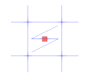
Join
Allows two separate conductors (1, 2) to be selected and generates a new conductor (3) that connects their ends.
| Note: |
|---|
| The manufacturer catalogues can be downloaded from the "Catalogues" option within the "Project" group. |
Editing tools
The main tools for editing the model are located in the "Edit" group of the main toolbar. Some of these tools are common to other CYPE programs.

The main tool area of this group allows the following operations to be carried out:
| Edit | Edits the parametric properties of the selected element in the model. | |
| Delete | Deletes a previously entered element. | |
| Move a group of elements | Moves a group of elements. | |
| Move | Moves an element or a node of an element. | |
| Rotate a group of elements | Rotates a group of elements. | |
| Rotate | Rotates an element about the "x", "y" or "z" axis. | |
| Symmetry (copy) | Copies a selection of elements with symmetry with respect to a vertical plane defined by two points. | |
| Symmetry (move) | Moves a selection of elements with symmetry about a vertical plane defined by two points. | |
| Copy | Creates a copy of one or more elements. | |
| Copy onto another floor plan | Creates a copy of one or more elements on another floor plan. | |
| Modify height position | Modifies the height position of an element by specifying a relative displacement or the absolute dimension. | |
| Measure lengths on plan | Measures lengths between defined points on the model. If a closed contour is selected, it also displays the area. | |
| Show/Hide incidents | Highlights the elements in which an error has occurred. Hovering the mouse cursor over these elements will display the message describing the error. |

Results output
Job reports
The program allows users to print the following reports directly or to generate HTML, PDF, TXT, RTF or DOC files:
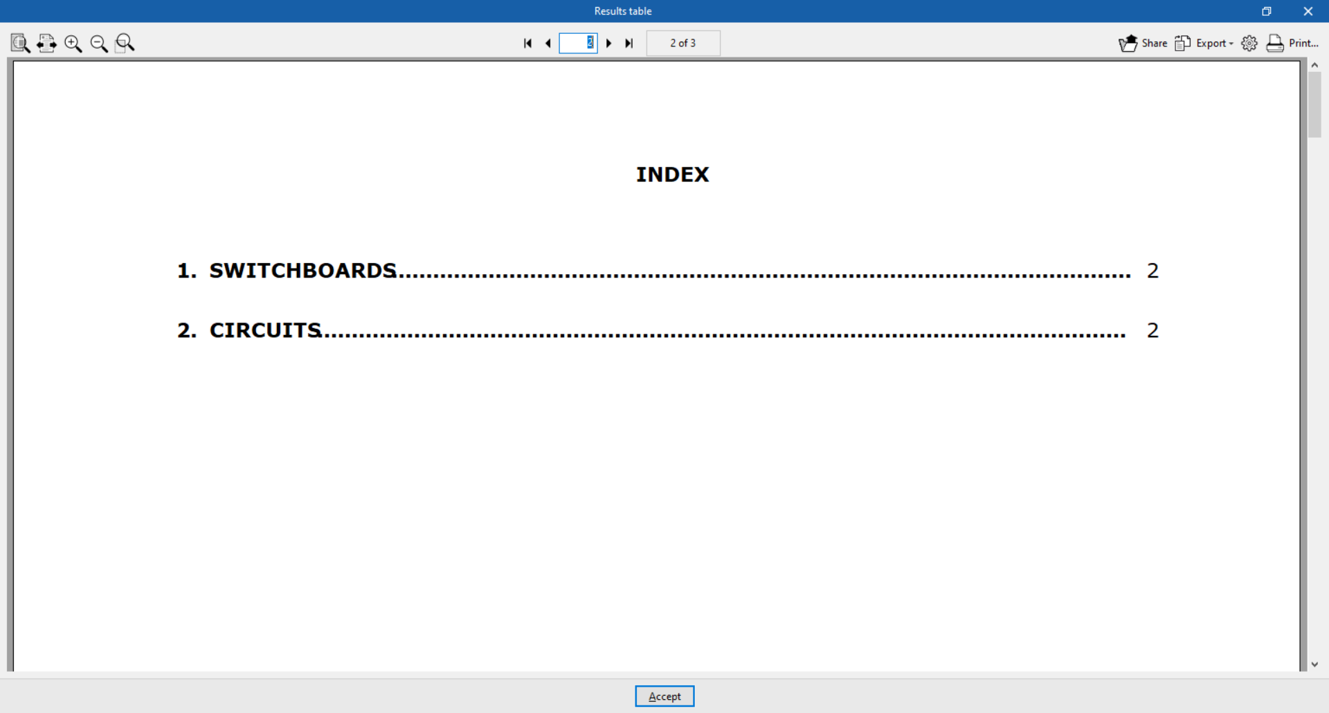
- Results table
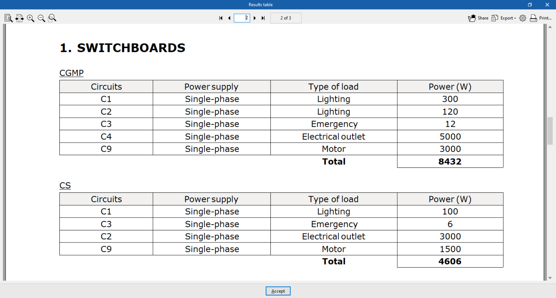
Displays a report with the results of the tables and circuits:- Switchboards
The switchboard data is organised into tables that include the following information:- Circuits
- Power supply of the circuit
- Type of load per circuit
- Power per circuit
- Total power of the switchboard
- Circuits
The circuit data is organised into tables that include the following information:- Types of receivers
- Power per receiver
- Power factor
- Demand factor
- Number of units
- Power per circuit
- Grounding systems
The grounding systems data is organised in tables including the following information:- Reference
- Type
- Total resistance of the assembly
- Switchboards
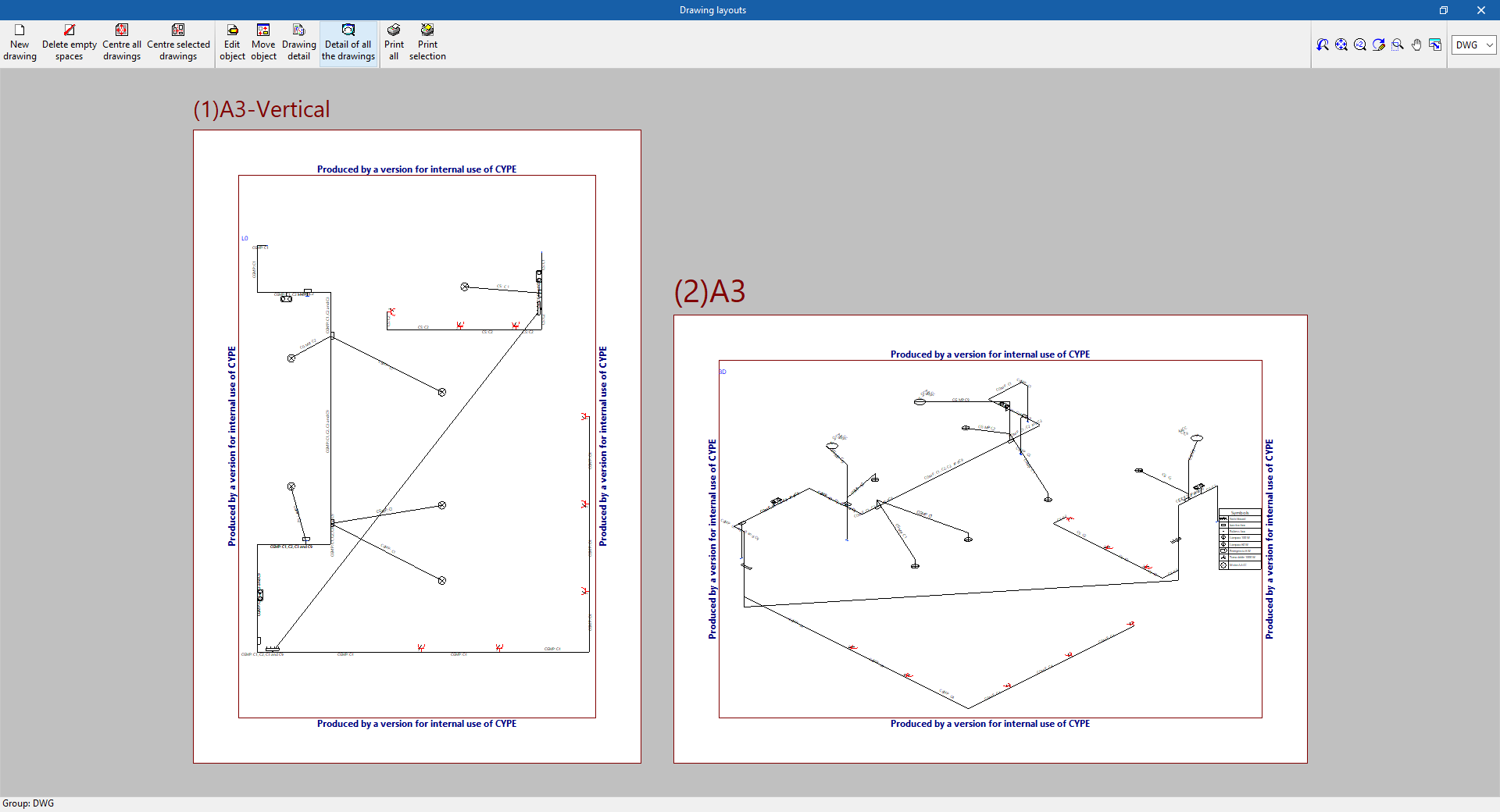
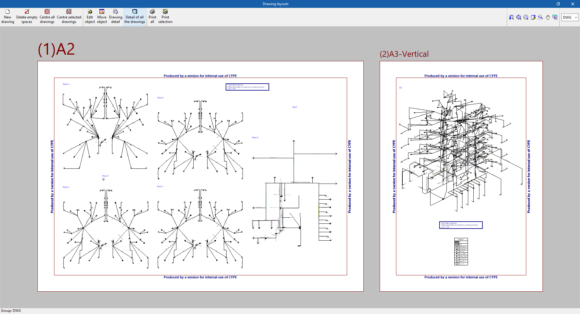
Drawings in DWG, DXF o PDF format
Allows users to print the job drawings on any peripheral device configured on their computer, or to create DWG, DXF or PDF files.
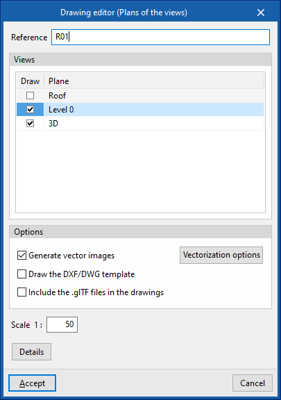
The following options can be configured when editing the drawing:
- Views to be drawn
- Options:
- Generate vector images
- Draw DXF/DWG template
- Include .glTF files in the drawings
- Scale
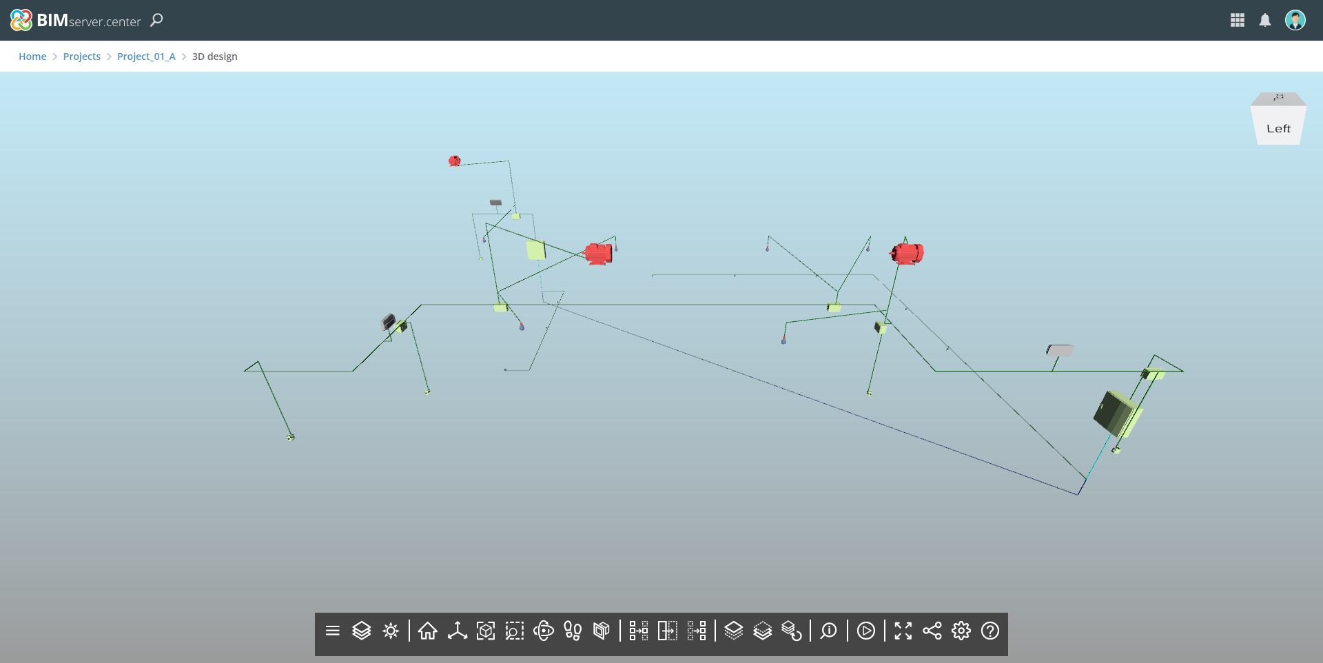
IFC and GLTF files supported by BIMserver.center
When exporting the project to the BIMserver.center platform, an IFC file and a 3D model in GLTF format are automatically exported for integrating the load and circuit distribution model into the Open BIM project, allowing it to be visualised:
- on the online platform;
- in the BIMserver.center app for iOS and Android;
- in virtual reality and augmented reality;
- in other CYPE programs.
Integration into the BIMserver.center platform
Many of CYPE's programs are connected to the BIMserver.center platform and allow collaborative work to be carried out via the exchange of files in formats based on open standards.
Please note that, to work on BIMserver.center, users can register on the platform free of charge and create a profile.
When accessing a program connected to the platform, the program connects to a project in BIMserver.center. This way, the files of the projects that have been developed collaboratively in BIMserver.center are kept up to date.

Options available in CYPELEC Distribution
The "BIMserver.center" group in the main toolbar contains the features required to use CYPELEC Distribution together with other BIMserver.center tools.

Update
Information contained in models previously imported into the project can be updated or new models can be imported if desired.
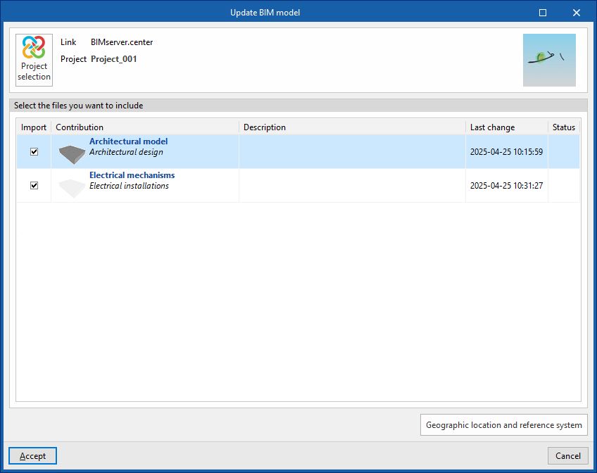
In the updating process, as in the process of creating a new job, the equipment requiring electrical supply can be read from the BIM model and assigned to one of the types of receivers defined in the project options. As a result, the program generates the receivers automatically or updates them according to the latest changes.
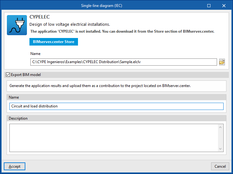
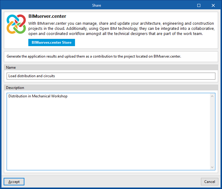
Share
Allows the information of the model developed with CYPELEC Distribution to be exported to BIMserver.center and shared with other users, including its three-dimensional representation and the system drawings.
During the export process, users can define information related to the identification of the files to be exported:
- Name
- Description
Direct connection with other programs
CYPELEC Distribution offers a direct connection option with Open BIM tools that allow further work. Through these options it is possible to send the CYPELEC Distribution BIM model to the following CYPELEC environments:
- CYPELEC Core
CYPELEC REBT (installation in Spanish)
CYPELEC RETIE (installation in Spanish)
CYPELEC NF (installation in French)
The different CYPELEC environments import the circuit distribution of CYPELEC Distribution electrical panels and subpanels to calculate the low voltage electrical system, generating the single-line diagram and checking and designing the conductor cross-sections and the necessary protection devices.