New features

2022.a Version

13 July 2021
Index

New programs

Open BIM Site (new program)

"Open BIM Site" is a free application for defining the initial conditions of a project site. With this tool, users can establish the geographical site of the models, manage different types of maps, enter topographic surfaces and add site-specific elements such as plots and buildings.

This application is integrated into the Open BIM workflow via the BIMserver.center platform.

"Open BIM Site" is an application with an international scope as it allows the site conditions of a construction project anywhere in the world to be specified. However, for projects located in Spain, the application includes a connection to two Spanish web services: the cadastre (Sede Electrónica del Catastro) and the Geographical Institute (Instituto Geográfico Nacional) in order to enter site data more easily, as well as obtaining maps and topographic surfaces.

More information.

New features common to several programs

Programs included in the Open BIM workflow

Managing project reference systems

As of version 2022.a, the applications integrated within the Open BIM workflow via the BIMserver.center platform include a tool for managing project reference systems. This option is available from the configuration window displayed during the process of linking or updating the BIM project.

The "Geographic location and reference system" panel displays the reference systems associated to the models that have been previously selected to be incorporated in the project located in the application where the work is being carried out. When a reference system is selected, it will be used as the local coordinate origin of the new model. We can see the following information related to a reference system:

  • Angular geographic coordinates
    If a location contains a definition of angular geographical coordinates, they will be displayed in this panel. The angular geographic coordinates allow the location of the model to be defined in the real world. This information can be used to calculate the natural lighting or perform the energy analysis of the project.
  • North
    The North direction is defined by the value of the angle relative to the positive Y axis of the project, in the anticlockwise direction. Like the angular geographic coordinates, the orientation of the building can be used to calculate the natural lighting or perform the energy analysis of the project.
  • Reference system of the location
    This indicates the coordinated position of the origin of the project location. Usually, the project location coordinate position is shown in UTM coordinates ("Universal Transverse Mercator").
  • Local reference system of the model
    The local reference system of the model indicates the position of the model with regard to the reference system of the location. If the "Link to the local reference system of the model" option is checked, the same reference system as the selected model shall be used. Otherwise, a different local reference system to the selected model site can be specified for the new job. The "Recover the local reference system of the model" button allows the coordinates to be filled with the data from the selected model when the "Link to the local reference system of the model" is active.

Programs with contour plots

New colour palette in contour plots

In all programs working with contour plots, a new colour palette has been added to the two existing ones. Furthermore, users can select the drawing mode with gradient colour or a colour wheel in all three palettes.

Implementing codes

Rolled and built-up section steel structures

Loads on structures. Wind loads

Loads on structures. Seismic loads

Implementation. NSE-18 (seismic loads Guatemala)

Structural safety codes for Guatemala 2018 (Updated 15/07/2020)

  • NSE-2 Demandas estructurales y condiciones de sitio. Capítulo 4.- Aspectos sísmicos.
  • NSE-3 Diseño estructural de edificaciones.

Implemented in CYPECAD and CYPE 3D.

CYPE Architecture

Copying from another level to multiple levels

The "Copy from another level" function allows users to copy to multiple levels simultaneously without having to repeat this command continuously to copy each one of the levels in a project in the case of a multi-storey building with multiple repeated floors.

New field for typology descriptions

Typologies now have a new "Description" field where a brief description of the typology can be added if necessary. This information can be consulted and used in programs that use the Open BIM workflow such as, Open BIM Layout and CYPE Construction Systems.

Open BIM Construction Systems / CYPETHERM LOADS

Importing construction systems by Grupo Valero

In the previous version (2021.f), the CYPE Construction Systems and CYPETHERM LOADS programs included the option of importing insulation from the manufacturer Grupo Valero to act as layers of the construction systems defined in these programs.

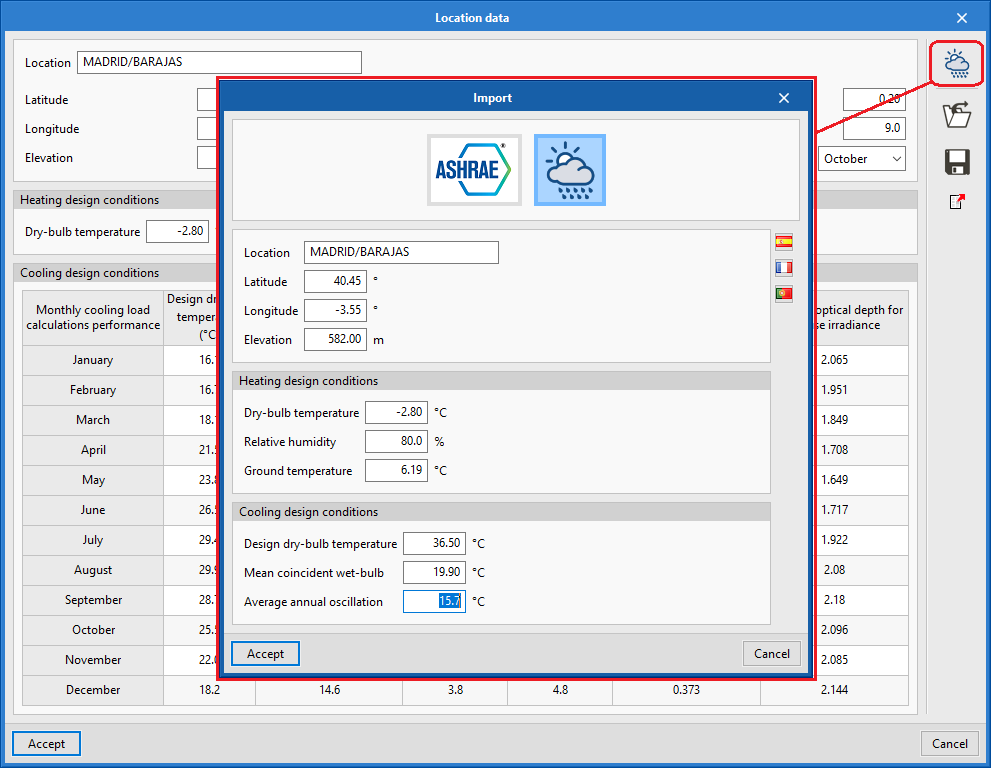
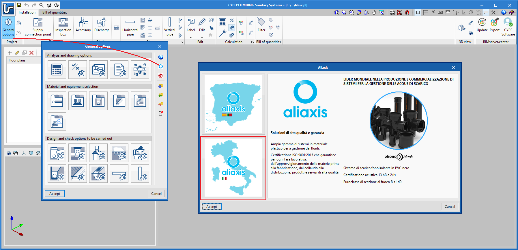
Now, in version 2022.a of the same programs, complete construction systems offered by the manufacturer Grupo Valero can be imported, including the products in their insulation catalogue. These systems can be imported using the icon displaying the Grupo Valero logo in the CYPE Construction Systems and CYPETHERM LOADS applications. Depending on the type of construction system to be defined, the corresponding group of products is shown: external walls, roofs, slabs between floors or floors in contact with the ground.

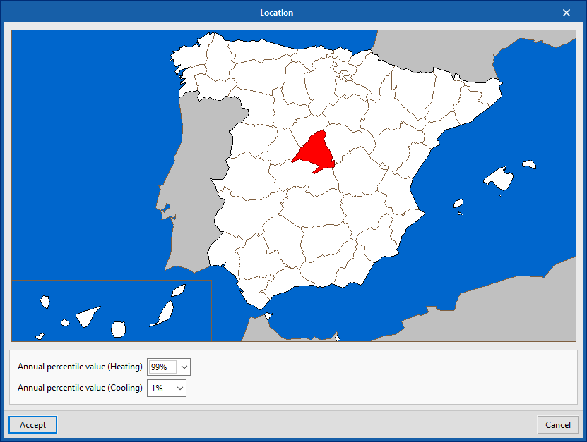
The components that appear in Grupo Valero’s construction solutions catalogue have been divided according to the climate zone where the project is located. Consequently, users must indicate this information before choosing the most appropriate solution. The selection panel shows the layers of the materials of which it is composed and their total thickness along with the system reference in order to facilitate this choice.

It is important to note that if the construction systems are defined in CYPE Construction Systems, it will not be necessary to reassign them in the thermal study applications as the information is transmitted via the Open BIM workflow.

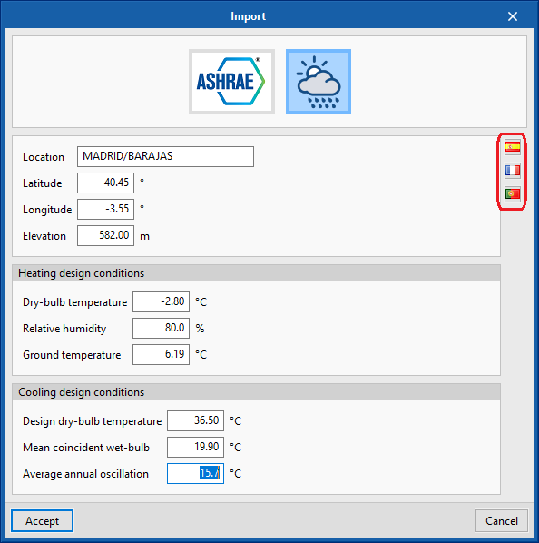
Although Grupo Valero icons can be found in all the languages in which the aforementioned applications are installed, the manufacturer’s construction systems shown correspond to the products supplied by Grupo Valero in Spain.

Open BIM Water Equipment

Connection with Open BIM analysis applications

Two new buttons have been added to the BIMserver.center group in the toolbar. These allow users to directly connect to the necessary tools for carrying out the analysis of the installations involving sanitary equipment entered in the BIM model, as well as the relevant code checks.

  • CYPEPLUMBING Water Systems. Potable water supply installations.
  • CYPEPLUMBING Sanitary Systems. Wastewater and rainwater evacuation installations.

Open BIM Analytical Model

Geometric definition of the analytical model

As of version 2022.a, Open BIM Analytical Model includes the IFC Builder tool which allows users to design a simple architectural model, suitable for generating the analytical model, in the same Open BIM Analytical Model project. To launch the tool, users must press the "Architectural modelling" button available in the "Project" group in the application’s toolbar.

Once the architectural model is finished, it can be sent back to Open BIM Analytical Model using the "Export" option available in the "Analytical model" group in the IFC Builder toolbar. As the model already contains analytical geometry, when generating the analytical model in Open BIM Analytical Model the "Use the outlines of the spaces defined in the IFC model" option in the configuration panel must be checked.

CYPECAD

Automatically importing beams from a BIM project

As of version 2022.a, beams can now be entered in a BIM project when they have a correct parametric definition in the IFC file (section + extrusion or section + faces). Users can import beams from our CYPE Architecture modeller, as well as from other BIM modellers.

Faster frame design

The frame design process has been modified in order to make better use of the available processors.

It is difficult to quantify the achieved improvement, however, the example below shows a comparison of the frame design times of various jobs. All calculations have been carried out on a computer with an "Intel(R) Core(TM) i7-8700K CPU @ 3.70GHz, 3696 Mhz, containing 6 main processors and 12 logical processors".

JobTotal surfaceTime in previous
versions
Time in current
version
Improvement
6-storey building650 m21'21"65%
ESC-RETICULAR (Example job)1440 m22' 26"1' 38"33%
10 storey building2619 m24' 14"1' 31"64%
19 storey building12208 m251' 19"26' 31"48%
20 storey building46746 m21h 5' 18"36' 58"43%
42 storey building61621 m24h 50' 54"2h 17' 51"53%

Post-tensioned tendons in any direction

When entering post-tensioned tendons, users are allowed to do so in any direction, although the preferred directions are those corresponding to the reinforcement of the floor slab. While the introduction is being carried out, a blue line is displayed if the direction matches those of the reinforcement of the floor slab and green in all other cases.

Other improvements and corrections

CYPECAD version 2022.a also includes other minor improvements and corrections of the program that could occur in rare situations:

  • Isolated footing reinforcement checks
    As of version 2022.a, isolated footing reinforcement checks will be carried out considering the number of actually placed bars. Previously, they were carried out with distributed reinforcement that could lead to certain inaccuracies, especially in the case of smaller footings.
  • Warnings during the analysis process
    • In the analysis process, certain warnings can be repeated throughout the analyses carried out in the same job. As of version 2022.a, users can choose not to see these warnings again.
    • Warnings such as "Diagonal bracing data has been modified. Re-analyse the job in order for this to be considered during the design" that appeared in previous versions each time a diagonal brace or sloped beam was analysed, are now only displayed with the first beam or diagonal brace that is modified.
  • The "Colours for representing contour plots" button has been added to contour plots.
  • The size of gltf files exported from CYPECAD has been reduced so that display in BIMserver.center is smoother.
  • Two buttons have been added for accessing the standard configuration of strap and tie beams in the "Strap and tie beams" menu.
  • The "Soil-structure interaction" option can be activated in the "Show References" option to show the subgrade modulus for footing and the axial stiffness of pile caps. This can be useful when assigning values in the "Soil-structure interaction" option.
  • The drawing of texts and foundation elements has been improved in the "Soil-structure interaction" option. Previously, the texts were not displayed clearly depending on the background colour.
  • Variable depth beams are correctly exported to IFC files. Previously, they were exported as constant depth beams.
  • Messages such as "The first floor of column P1a is the same as the last floor of the column on which it starts" have been removed for columns starting on other columns.
  • An error that occurred when adding floors to a job with shear walls whose reinforcement was blocked has been fixed.
  • An error that occurred when the seismic analysis was carried out with code ASCE 7-16 in cases where the ductility or the displacements factor is less than 1 has been fixed.


CYPE Connect Steel / StruBIM Steel

Connections library

In version 2022.a, a connection library has been added, allowing users to save defined connections so they can be applied to other nodes of the same or other jobs. This library is common to CYPE Connect Steel and StruBIM Steel.

From the connection editing panel, users will have access to the added options: Import from library, Export to library and Connections library.

  • Import from library

    This tool allows users to import the list of operations from a connection from the library.
  • When importing, if the section layout is not identical to the one saved in the connection, users will be asked to match the sections of the library with the sections of the current node.
  • Export to library
    Allows a connection to be saved in the job’s connection library. By clicking on "Export", the program will request users to define the reference to save it in the job library.
  • Connections library
    The connections saved in the library will be available for use in the job itself. To save the connections in this library in the drive and to be able to use them in other projects, share them between CYPE Connect Steel and StruBIM Steel, or share them with other computers, users must click on "Export the element to a file".

    The management of this library works in the same way as the other libraries. The following options related to the management of this library are shown at the top:

    • Import the elements saved in the drive to the project
    • Update the elements used in the project
    • Export the element to a file
    • File selection with initial values for the creation of a new job

Connection summary report

The connection summary report has been added. Connection elements, section loads, or the checks of sections, plates, fillet butt welds, and bolts can be displayed in a summarised form in this report.

From the "Report" button in the main CYPE Connect Steel window, the report can also be generated with a summary of the nodes selected by the user.

Optimisation of analysis time

Optimisations have been implemented in the connection analysis process. With these optimisations, the analysis time has been reduced by approximately 30% according to the tests carried out.

CYPE Connect Steel

Node management in the 3D view of the structure

Up until version 2022.a, the program automatically generated nodes when the project had been created by importing from a structure in IFC format.

In version 2022.a, node management from the 3D view of the structure has been added. The following tools have been added to the top bar of options.

  • Create a node by selecting sections in the 3D view.
  • Edit the selected node in the 3D view.
  • Delete the selected node in the 3D view.
  • Edit the selected connection in the 3D view.
  • Coordinates of the positions of the nodes. This option allows nodes to be located in the space.

The 3D view of the node selected from the node list will be displayed in the lower-left window. If a structure has been imported, it will be shown in the window on the right.

The nodes in the list on the left are managed from the bar of options immediately above it.

Viewing options

Options for viewing the structure and drawing connections in a 3D view have been implemented.

These options allow sections to be represented by drawing their axis or the 3D model. Additionally, users can choose whether or not they wish to draw the defined connections.

CYPELEC Core

Additional cable length in circuits

When editing any type of circuit that can be defined in a single-line diagram, the possibility of entering additional cable length is included. This length may include, for example, the connection between junction boxes and switches to complete the lighting points or branches that the circuit may include in its installation that may not have been considered for the cable design, but which have been taken into account for its total bill of quantities.

The total quantities of the cable are displayed in the material schedule report.


CYPELEC Distribution

Concentrated load as an option to calculate the demand of the electric circuit

A new option for calculating the power demand and length of the circuit called "Concentrated load" has been added. Thus, the options available for the calculation of electrical circuits are as follows:

  • Foreseen load. The total power and the length of the circuit are entered manually. The circuit will act as a circuit with its entire load concentrated at the end of the circuit.
  • Distributed load. The power of the circuit will be given by the assignment of the loads and the length of the supply path. The circuit will act as a circuit with the loads distributed in its position.
  • Concentrated load (new option). The power of the circuit will be given by the assignment of the loads and the length of the distance to the furthest load so, in this case, the supply path is not required. The circuit will act as a circuit with its entire load concentrated at the end of the circuit.

CYPELEC PV Systems

Division of the installation analysis

The installation analysis has been divided into two parts:

  • Analysing conductor and inverter checks.
  • Analysing photovoltaic generator power.

This way, if the "Analyse energy produced by the photovoltaic generator" option in the "Checks" window is not selected, only the requirements of the elements making up the installation will be checked, speeding up the analyses. Once all the conductors and inverters have been designed, the "Analyse energy produced by the photovoltaic generator" option can be selected, thus calculating the shade.

MPPT settings in inverters

The "Number of MPPTs" parameter has been added to the definition of the inverters in the element library. This way, the number of inverter trackers can be defined, as well as the maximum intensity per MPPT.

Therefore, once analysed, the invertor’s defined inputs shall be checked.

CYPEPLUMBING Sanitary Systems

Introducing aliaxis analysis settings for Italy

As of version 2022.a, the Phonoblack catalogue by the manufacturer Aliaxis is included in CYPEPLUMBING Sanitary Systems for the Italian market.

In "General options", users can select the Aliaxis icon and, from there, select either Spain-Portugal or Italy to import the different catalogues that include the analysis checks of the elements they contain.

CYPETHERM LOADS

Generation of climate data based on design conditions

With this new data import assistant, users can generate the total climatic data requested by the program which is required for analysing thermal loads, based on main location data (design conditions).

This new feature is added to the existing feature of importing data based on the ASHRAE climatic database (ASHRAE Weather Data Viewer 6.0).

Additionally, to facilitate the introduction of these minimum design conditions, an assistant has been implemented to allow them to be imported from the location selected on a map, a feature available for locations in Spain, France and Portugal.

Arquimedes

Preview of bills of quantities and cost databases

To make it easier to search for bills of quantities or cost databases, the Show contents option has been added, which allows the content of a bill of quantities or a cost database to be previewed.

The Show contents option can be accessed in two ways:

  • When no bill of quantities or cost database is open
    In this case, a window appears where budgets, cost databases or examples included in the program can be selected.
    If any of the following options are selected: "Budget", "Cost database" or "Examples", a list of databases appears. When right-clicking on any of the databases, a context menu with the option "Show contents" will appear.
  • When there is a bill of quantities or cost database open
    The "Show..." option" ("File" menu > "Recent bills of quantities" or "File" menu > "Recent cost databases") launches a window in which the recently opened databases are displayed. When right-clicking on any of the databases that are not currently open, a context menu will appear with the "Show contents" option.

Ope BIM Cost Estimator

Direct links to other applications

As of version 2022.a, CYPE Cost Estimatorincludes a direct connection to the construction site management application, Open BIM Site. For this purpose, the "Site" button has been added to the BIMserver.center group in the application’s toolbar. Using this option, the data related to the budget estimate will be exported to the BIMserver.center project and the Open BIM Site tool will be automatically launched to continue with the development of the project according to the usual workflow.

Open BIM Quantities

New example job

The example job "Intro Open BIM (EN)" has been added along with its cost database and set of measurement rules ("English - Intro Open BIM"). It is the first example implemented in technical English in the program, including both the model from the CYPE Architecture application and the bill of quantities in Open BIM Quantities.

Multi-line text field in "Set of measurement rules"

The "Reference" and "Detail line" text fields that appear in the panel for adding a new item in a rule of measurement contained in set measurement rules have been changed to multi-line fields. This way, it is now simpler to enter long references and detail lines with multiple variables.

Open BIM Quantities and applications with a "Bill of quantities" tab

Help window for types of waste

A help button has been added to the waste type selection in the panel for adding a waste component to the decomposition of a concept. Both the types of waste and their definitions are based on the specifications in the Spanish exchange format, FIEBDC-3/2020.