
Scope of the application
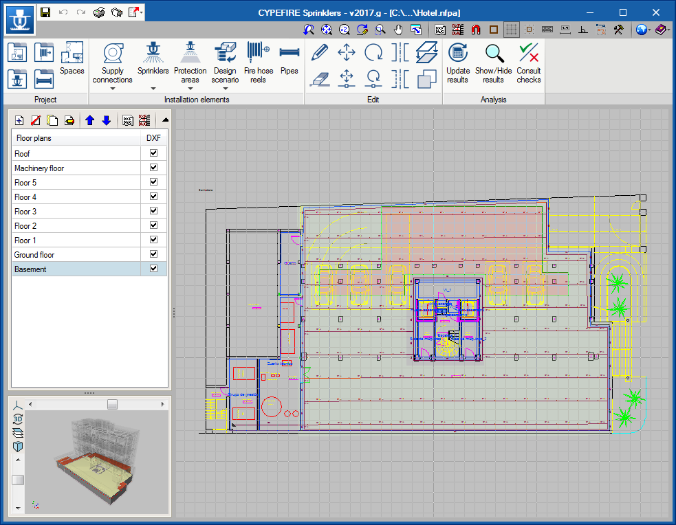
CYPEFIRE Hydraulic Systems allows the sizing and design of hydraulic fire extinguishing networks using sprinklers and fire hose reels (FHR) in accordance with different predefined codes, as well as designing installations by creating customised configurations for calculating other codes or for personal technical purposes.
| País | Code |
|---|---|
 | CP 52 : 2004 (Singapore Standard - Code of practice for automatic fire sprinkler system) |
 | EN 12845:2016 (Fixed firefighting systems - Automatic sprinkler systems - Design, installation and maintenance) |
 | NFPA® 13 (National Fire Protection Association) |
| Customisable codes |
Program properties
CYPEFIRE Hydraulic Systems allows users to design, analyse and size a fire extinguishing installation composed of sprinklers. The program carries out the necessary hydraulic calculations and checks to ensure the requirements of the NFPA®13 standard are met. These include:
- Hydraulic design of grid and branch systems
- Horizontal and vertical pipes
- Flow and minimum pressure in the sprinklers
- Distribution of the sprinklers
- Maximum allowable distance between sprinklers
- Maximum distance between the sprinklers and the wall
- Design of the tank
- Design of the fire hose reels
Hydraulic calculation
Calculation engine
CYPEFIRE Hydraulic Systems uses the EPANET 2 calculation engine (developed by Water Supply and Water Resources Division National Risk Management Research Laboratory) to carry out the hydraulic calculations necessary for designing sprinkler networks and fire hose reels (FHR).
EPANET provides accurate calculation results, which are suitable for compliance with any of the codes available in the application or those that are manually entered by the user.

EPANET allows calculation equations to be selected for solving load loss equations. By default CYPEFIRE Hydraulic Systems calculates according to the Hazen-Williams equation but can be solved using the Darcy-Weisbach equation, which is required for certain cases in the NFPA 13 code.
Sprinklers
CYPEFIRE Hydraulic Systems allows the following types of sprinklers to be used:
- Standard Sprinkler
- Standard Sprinkler Sidewall
- Residential Sprinkler
- ESFR Sprinkler

As well as their typology, the application allows all operation-related parameters to be modified (orientation in the installation, K factor, sprinkler thread size and response speed). Sprinklers can be defined either within the program or imported from the CYPEFIRE Hydraulic Systems predefined sprinkler library.
Introducing and designing sprinkler networks requires careful consideration due to the geometrical checks that must be carried out to comply with each of the codes. To facilitate and speed up this process, CYPEFIRE Hydraulic Systems offers different ways of introducing sprinkler networks.
- Manual introduction
Individual introduction for each sprinkler in the system, very useful for areas with complex geometry. - Branch introduction
The simplest option among those available, it allows a complete branch to be introduced (selecting the type of sprinkler and pipe to be used) according to the length chosen by the user. - Introducing a tree system
A slightly more complex option that allows users to enter a tree system by selecting the number of sprinklers on each side and the length of the cross main. - Introducing a gridded system
Similar to the previous option, but this time a gridded network is introduced by defining the number of sprinklers in each of the branches. - Generating a network
The automatic generation of a sprinkler network allows users to decide whether they want a cross main with branch lines or a gridded network, and by simply selecting the spaces, the desired network is generated.
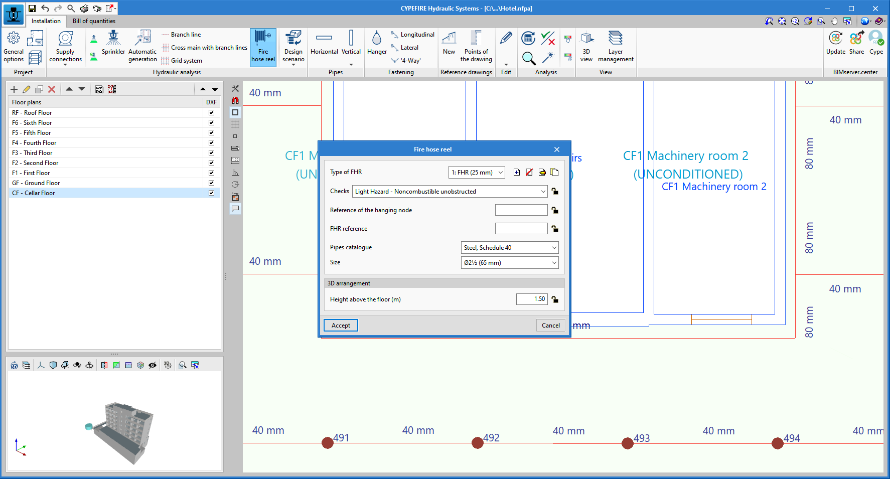
Fire Hose Reels (FHR)
CYPEFIRE Hydraulic Systems also allows Fire Hose Reels to be designed and analysed, either as an analysis method providing a fixed flow that oversizes the sprinkler system or as another element in the system that must comply with the minimum pressure and flow conditions necessary according to the code applied.
Load loss
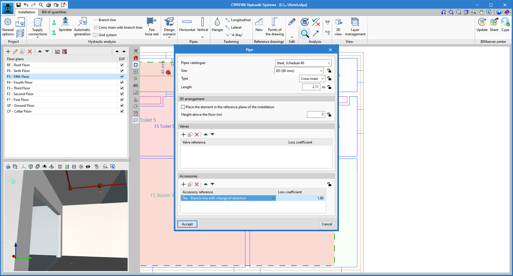
CYPEFIRE Hydraulic Systems provides two ways of calculating load losses produced by the singular elements (accessories and valves) of sprinkler networks and/or fire hose reels.
- Equivalent length method
In this case, the program increases the lengths of all the pipes in the system to consider all the accessories and valves in the network. This increase coefficient can be edited by the user and is not activated by default.
- Loss coefficient
By default, CYPEFIRE Hydraulic Systems carries out the analysis of localised pressure losses by means of the loss coefficient of each of the accessories or valves entered in the network. Furthermore, the application can automatically generate the necessary accessories according to the pipe network entered (elbows, tees, crosses).
Automatic pipe sizing
Analysing and designing an automatic sprinkler system can be quite complex. All the hydraulic calculation requirements that comply with the various applicable codes make selecting the size of the pipes to be used one of the most complex tasks when designing the system.
The sizing tool can be configured by the user in “General options > Sizing rules”. From this panel, it is possible to edit the diameters to be used for sizing and the maximum number of sprinklers that each diameter can feed until the next diameter is reached.
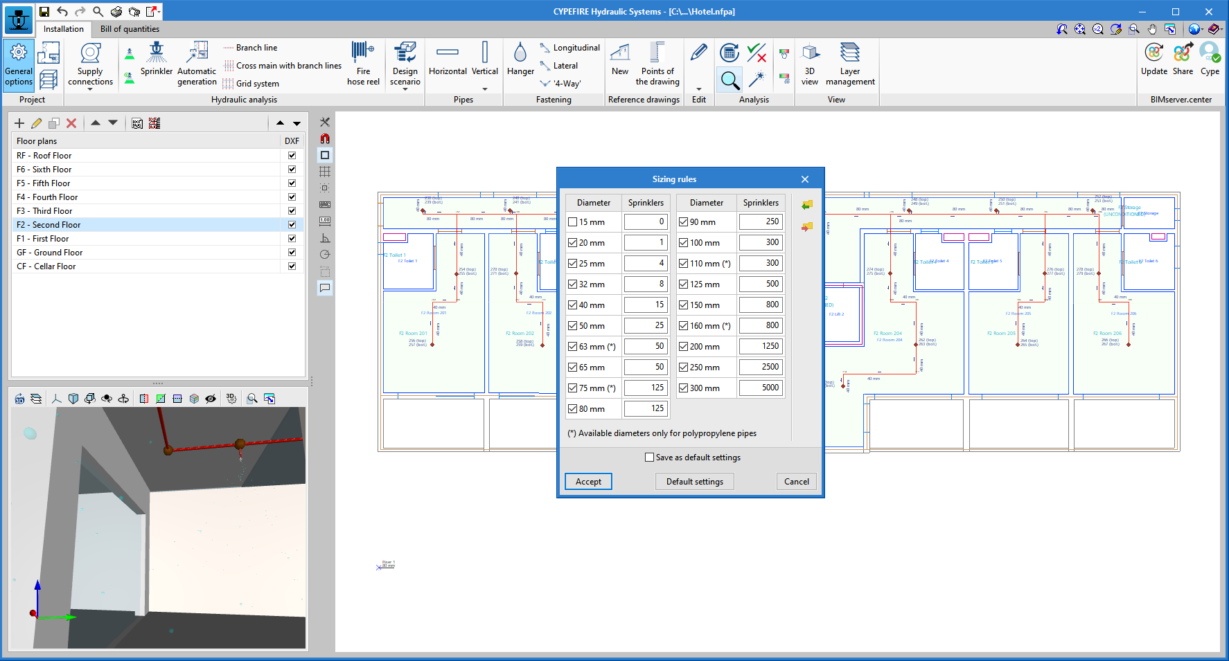
If no changes are to be made to the default data, the " Sizing " tool will start the diameter selection process and then the hydraulic analysis. This selection and hydraulic analysis process will end if no errors are found when comparing the results obtained with the code requirements. Otherwise, the process shall be repeated until valid diameters are selected to comply with the applied code.
Fastening
Hangers
Designing the hangers to keep pipe installations fixed to a building is a task that is easily solved with CYPEFIRE Hydraulic Systems. From the application, the predefined hanger catalogue can be used or a new catalogue can be entered manually.
Once the type of hanger to be used has been selected, users must consider the distribution of the hangers throughout the system so that the weight is evenly distributed.
Seismic brace assemblies
The NFPA 13 code includes a number of checks for designing seismic supports. These checks have been implemented in CYPEFIRE Hydraulic Systems so that this type of element can be correctly introduced wherever it is required (the west coast of North America is the area covered by NFPA 13).
To design this system, the application has the following element catalogues:
- Sway bracers catalogue
- Braces catalogue
- Fasteners catalogue
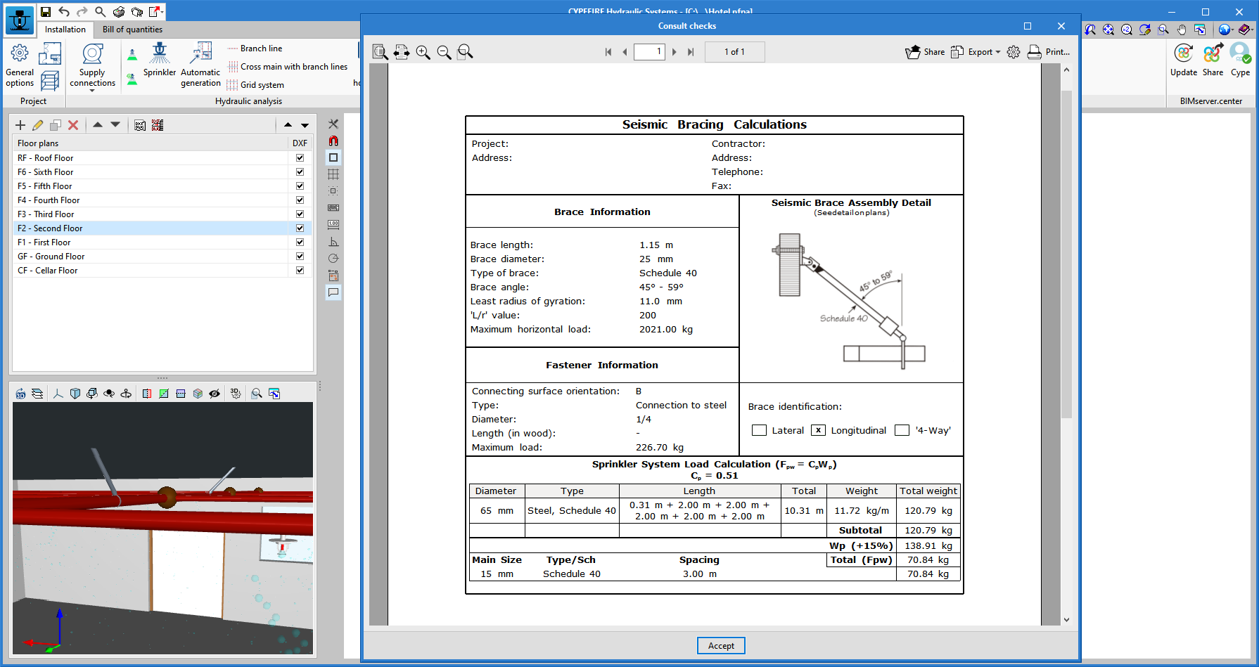
The application can introduce the different seismic brace assemblies that will reduce movement produced by earthquakes with these three elements:
- Longitudinal seismic support
- Lateral seismic support
- '4-way' seismic support
Bill of quantities
In the “Bill of quantities” tab, users can find tools for generating and managing the system's quantities and cost estimations. Here, users can extract the model’s bill of quantities and generate real items using that information. This process is carried out by means of a corresponding system between the elements measured on the analysis model and the concepts of the bill of quantities (mapping). This equivalence is stored in a local or network file so that it can be progressively expanded and used in future projects.

To facilitate entering prices for the job, it is possible to import both complete databases and individual concepts from cost databases that have been developed in accordance with the FIEBDC-3 standard (.bc3).
The quantities and cost estimations documents can be extracted in several reports (Quantities, Cost breakdown structure, Detailed priced bills of quantities, BoQ summary) exportable in HTML, DOCX, PDF, RTF and TXT formats.
Checks, reports and drawings
Once the sprinkler systems and hydraulic analysis have been defined, CYPEFIRE Hydraulic Systems carries out the checks corresponding to the NFPA®13 standard and generates the justification reports and required drawings.
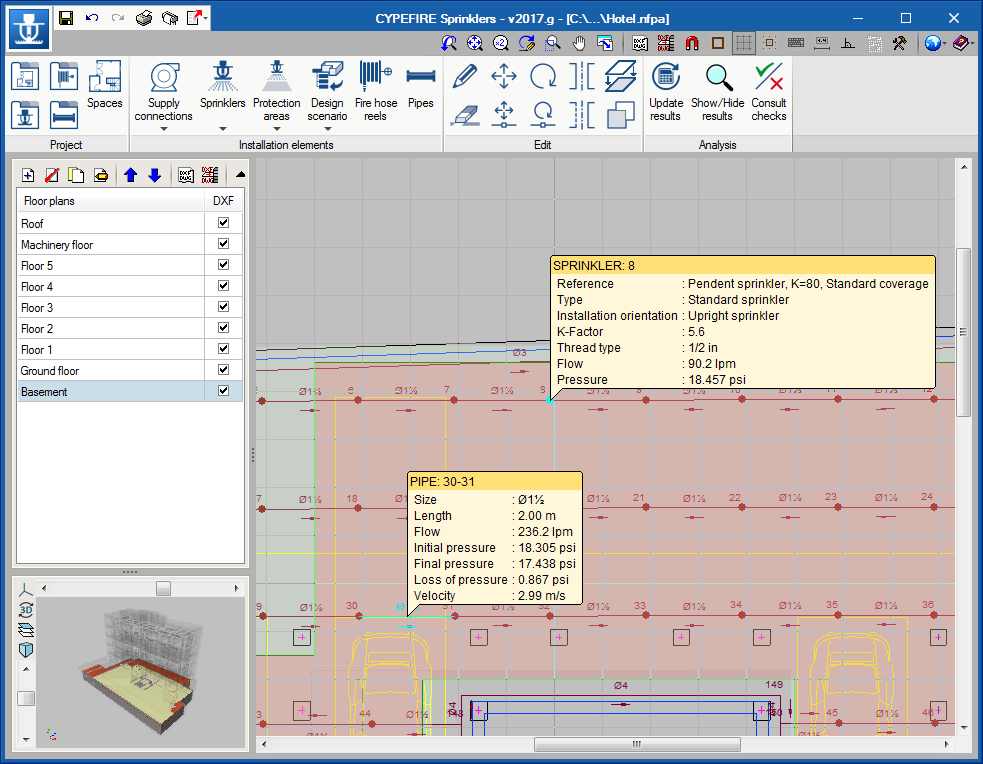
On-screen results
Once the hydraulic design and checks have been carried out on the system, CYPEFIRE Hydraulic Systems can provide an on-screen display of any errors or information on the results of the hydraulic design and the design of the sprinkler system.
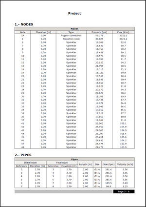
Justification files
CYPEFIRE Hydraulic Systems generates the justification files that are necessary to meet the requirements of the NFPA®13 standard, such as:
- Analysis of the nodes
- Flow in the sprinklers
- Pressure in the sprinklers
- Elevation of the nodes
- Analysis of the pipes
- Elevation and length of the pipes
- Diameter used
- Flow and velocity of the fluid
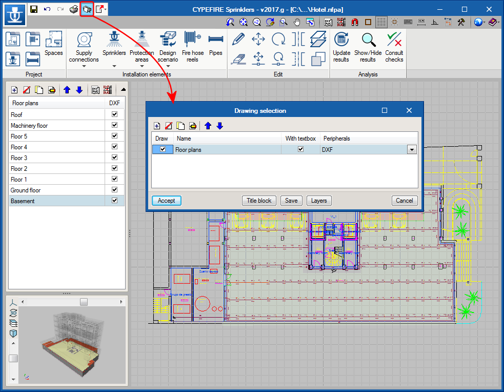
Installation drawings
The program provides detailed drawings of the installation of the sprinkler system. It provides a tool that allows users to configure the floor plans that will be represented in the drawings.
Users can print the drawings directly or export them to different formats (DWG, DXF, PDF, XPS).
User license
In order for CYPEFIRE Hydraulic Systems to be able to carry out the aforementioned specifications, the user license must include the "CYPEFIRE Hydraulic Systems" permission.