Update history​​

CYPE 3D

As of the 2019.d version, CYPECAD, CYPE 3D and Continuous beams allow users to edit the percentage of live load to be considered as quasi-permanent load to take it into account when calculating the differed deflection. To do so, the “Construction process” panel has been included in the “% Quasi-permanent” field. 

The panel can be accessed as follows:

  • CYPECAD
    In CYPECAD, users can indicate a different live load percentage as quasi-permanent load for each floor group:


    Project > General data > Permanent and live load > “Edit” button of the floor in question.
  • CYPE 3D
    Project > General data > Construction process
  • Vigas continuas
    General data > Construction process

As of the 2019.a version, CYPECAD and CYPE 3D can take into account the effects of the vertical seismic component by considering them as a percentage of the gravitational effect. Optionally, both programs apply a modification or adjustment coefficient that acts as the sum of the factor of the permanent loads in the seismic force combinations.

This coefficient increases the factor of the permanent loads in seismic combinations for unfavourable gravitational conditions and decreases the factor of the permanent loads for favourable gravitational conditions. In the first case, the gravitational effects are added to the seismic effects. In the latter, the gravitational effects counteract the seismic effects.

Consideration of the effects of the vertical seismic component

In building design, it is usual to calculate a structure to against the horizontal action of the earthquake and neglect the effects of the vertical component. However, in certain cases, it is advisable to consider these effects in the design.

CYPECAD and CYPE 3D apply an alternative procedure to the specification of spectra to consider the vertical seismic action, including its effects in seismic combinations by increasing the effect of the permanent load. This increase takes positive and negative values, due to the reversibility of the seismic action, and increases and decreases the gravitational effects in the combination. By doing so, the effects of vertical movement of the floor in buildings are simulated, such as:

  • The variance of the axial force in elements that resist vertical loads.
  • The variance in the localised deformation at the top of columns and the deflection at floor slab mid-spans.
  • The variance of the total vertical shear force that is transferred between floor slabs and columns.

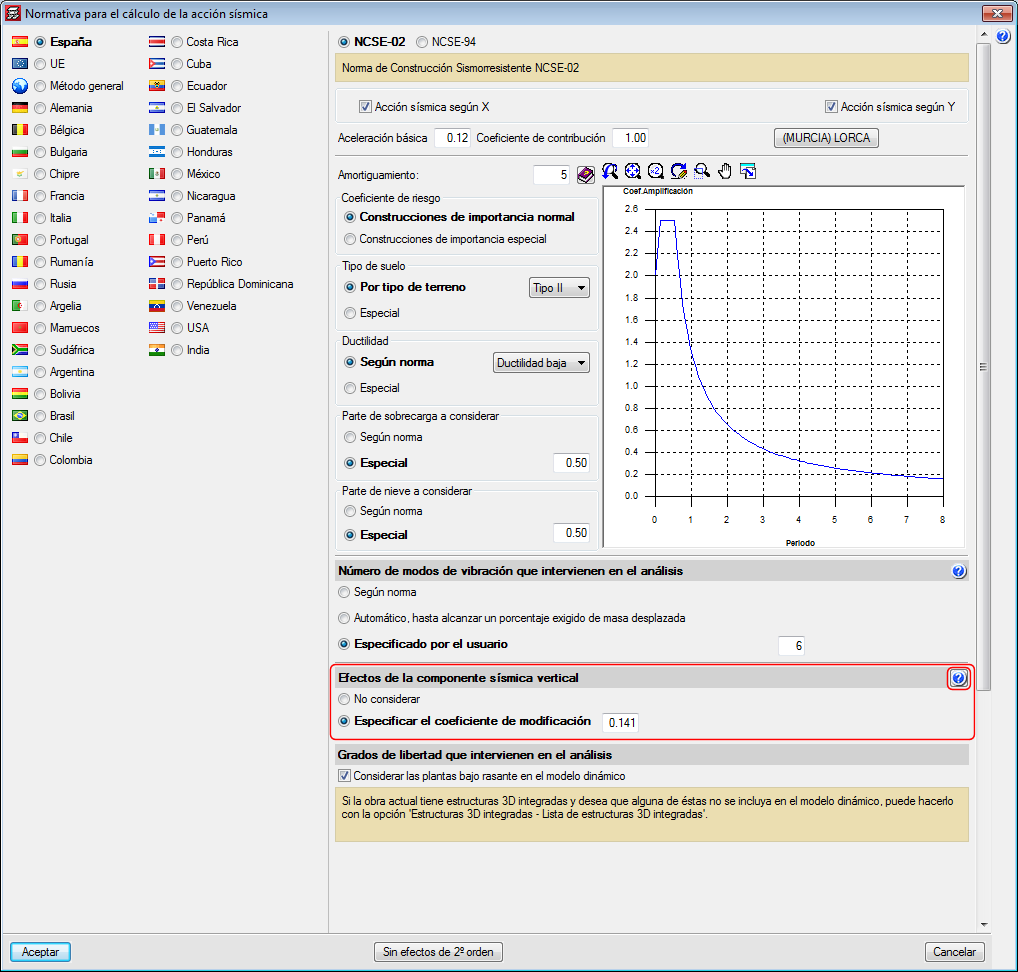
CYPECAD and CYPE 3D propose a simple calculation for this modification coefficient, which provides a value that adapts to what is established in the standards and that is a function of the seismicity of the site that has been selected by the user. Some codes call it "vertical seismic pseudo-acceleration", but it does not represent the total vertical response, only the part that is combined with the horizontal response and the effects of gravity. The data proposed by the program can be modified by users, since different situations to those usually contemplated by the standards may arise.

In the section of the seismic data dialogue where users can activate whether or not the effects of the vertical seismic component are to be considered, there is a help button where more information on the calculation of the "vertical seismic pseudo-acceleration" coefficient can be found.

In the 2019.a version of CYPECAD and CYPE 3D, users can now define steels for which they can indicate their elastic limit. The modulus of elasticity, thermal expansion coefficient, density and Poisson's ratio are defined internally by the program using the values of the steel. For U.L.S. checklists, the type of steel that is used can be seen.

As well as the elastic limit and depending on the selected code, additional data may be required to design connections.

The user steel library can be accessed from General Data. Rolled or cold-formed steel can be assigned to the sections as can steels that are established by each standard.

User-defined steels can be exported to the library to be used in other projects. They can also be selected as initial steels for the creation of new projects. The library is common to CYPECAD and CYPE 3D.

  • In CYPECAD:
  • In CYPE 3D

The following types of steel have been incorporated to the AISI S100-2007 cold-formed steel code: F-20, F-22, F-24, F-26, F-30 and F-36 (of common use in Argentina).

As of the 2018.k version, if the selected concrete code is the “NTC 2017 (Mexico City)” code, the following earthquake codes of Mexico can be selected (as well as the NTC 2017 itself):

  • CFE 2015
    Manual de Diseño de Obras Civiles. Diseño por Sismo. Sección C: Estructuras. Tema 1: Criterios generals de análisis y diseño. Mexico 2015.
  • CFE 2008
    Manual de Diseño de Obras Civiles. Diseño por Sismo.

Normas Técnicas Complementarias. Diseño por Sismo (2017).

Implemented in CYPECAD and CYPE 3D.

Normas Técnicas Complementarias. Diseño y Construcción de Estructuras de Concreto (2017).

Implemented in CYPECADCYPE 3D and StruBIM Deep Beams.

The following new types of cold-formed steel have been added for the EAE 2011 code (Spain) and Eurocodes 3 and 4 (EU):

  • DX 51 D+Z
  • DX 52 D+Z
  • DX 53 D+Z
  • HX 260 LAD
  • HX 300 LAD
  • HX 340 LAD
  • HX 380 LAD
  • HX 420 LAD

The possibility to add comments to the project has been implemented. The comments are managed in the “Job description” dialogue box (File > Job description).

The comments users add can be included in the Project report. This improvement allows, for example, users to manage a history of comments, modifications or revised versions of the project.

Decree 945 of 5 June 2017 published by the Ministry of Housing, City and Territory of the Republic of Columbia partially modifies the “Reglamento Colombiano de Construcción Sismo Resistente NSR-10”.

In the 2018.c version of CYPE programs, the changes indicated in this decree, which affect CYPECAD and CYPE 3D, have been implemented. These changes allow users to select certain municipalities that were previously omitted in the NSR-10 Regulation.

The municipalities that have been added are: Norosí (Bolívar), Guachené (Cauca), San José de Uré (Córdoba), Tuchín (Córdoba), Nariño (Nariño) and Coveñas (Sucre).

CRITERIA FOR EARTHQUAKE RESISTANT DESIGN OF STRUCTURES. Part 1 General Provisions and Buildings.

Implemented in CYPECAD and CYPE 3D.

As of the 2018.a version, CYPE 3D includes the analysis, design and check of prequalified connections in accordance with ANSI/AISC 358-10 (Prequalified Connections for Special and Intermediate Steel Moment Frames for Seismic Applications) and ANSI/AISC 341-10 (Seismic Provisions for Structural Steel Buildings).

Prequalified connections are applied to Special Moment Frames (SMF) and Intermediate Moment Frames (IMF) as indicated in the ANSI/AISC 341-10 code.

It is possible to define prequalified connections in projects in which the rolled and welded steel code: ANSI/AISC 360-10, has been selected.

Implemented prequalified connections

The prequalified connections that have been implemented in the program are:

  • 4E four-bolt unstiffened
  • 4ES four-bolt stiffened
  • 8ES eight-bolt stiffened

Nodes with interaction of several beams

Column-beam prequalified connections can be part of a node interacting with connections of other beams, which can or cannot be prequalified connections. For example:

  • Prequalified 4E connection to the flange of the column and moment connection to the web of the column and ordinary front plate.


  • Prequalified 8E connections to the flanges of the column and pilled connection using lateral plate to the web of the column.

Checks and drawings

As well as the checks carried out on the connection in accordance with the ANSI/AISC 360-10 rolled steel code, specific checks of the ANSI/AISC 341-10 and ANSI/AISC 358-10 codes are carried out. The check report displays the chapter of the code in accordance which the check is performed.

Operation in CYPE 3D

For CYPE 3D to carry out the analysis, design and check of prequalified connections of columns and beams, the following conditions must be met:

When the type of earthquake-resistant system is assigned to columns and beams, it is also possible to:

  • Define the height of the higher floor to check the shear in the node panel
    This parameter can be calculated by the program or established by users. It is used to calculate the shear of the column above that would affect the check of the shear in the node panel.
  • Check as connection without lateral support in the direction of the seismic frame
    Users can choose whether or not to carry out this option depending on the bracing there may be in the elements of the connection. This check is only carried out for SMF frames.
  • Free span of the beam, between column faces
    Value required to calculate the moment at the face of the column, this value can be calculated by the program or provided by users.

CYPE Mentor