As of version 2024.f of CYPE 3D, users can define buckling analysis groups to independently analyse the buckling behaviour of different sets of elements in the structure.
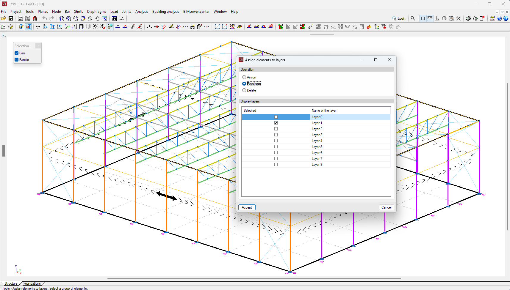
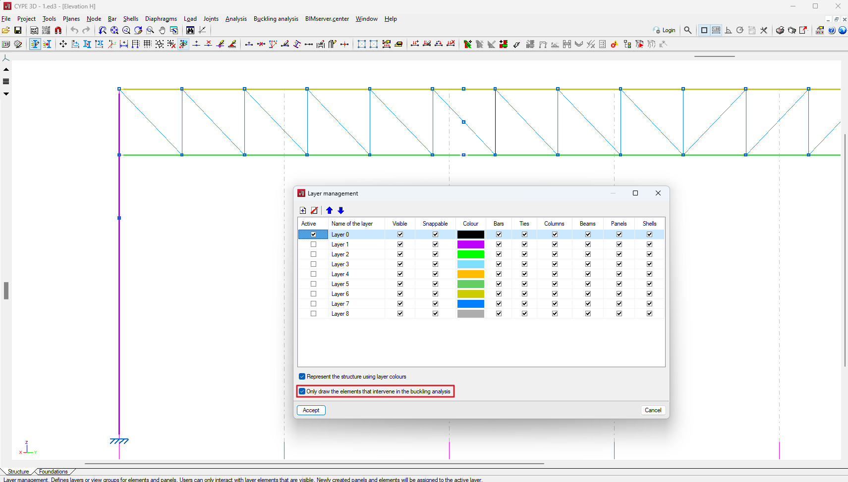
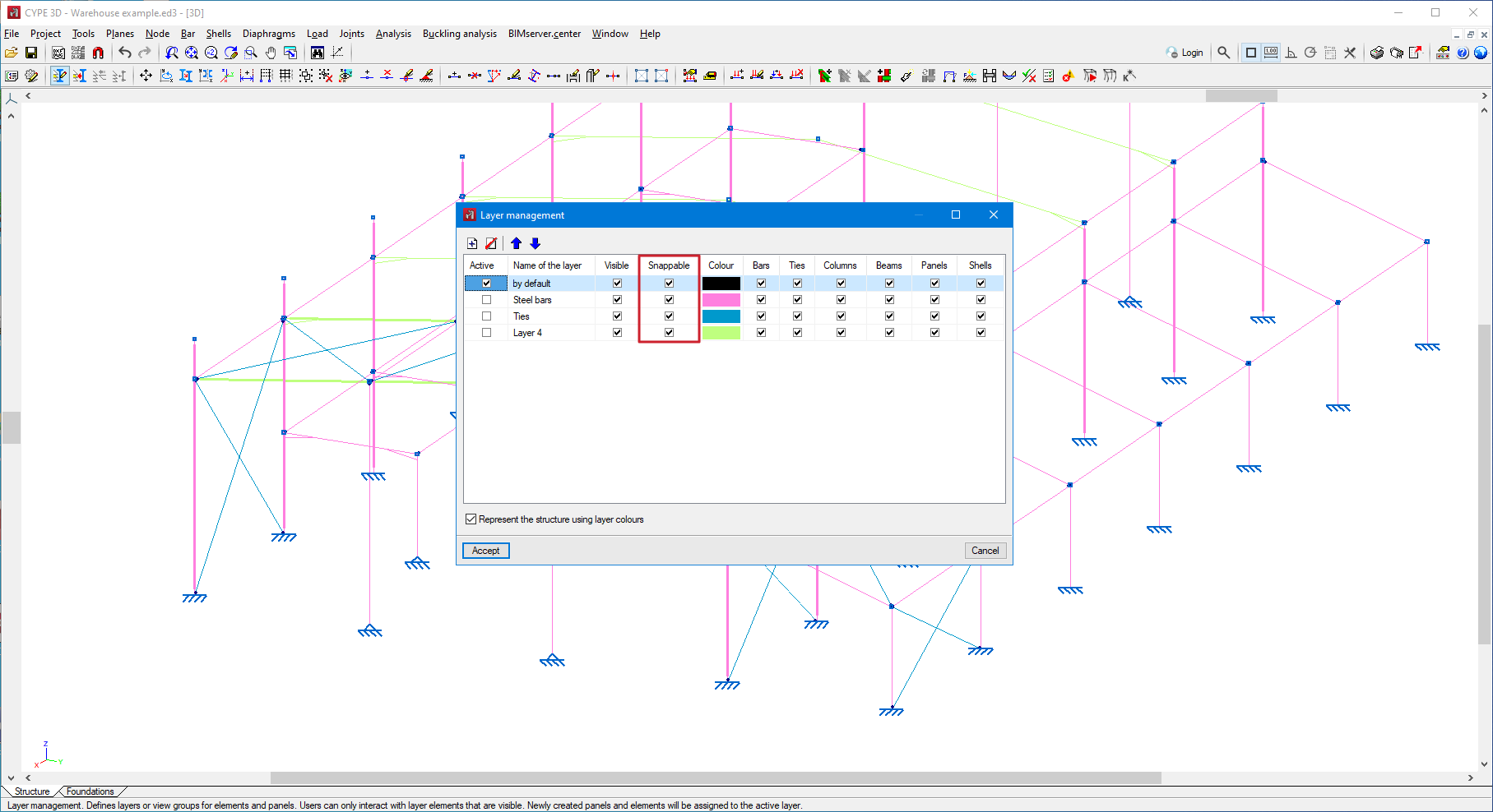
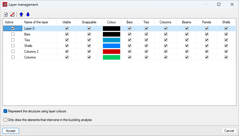
Groups are defined using the "Analysis groups" option in the "Buckling analysis" menu and are based on the layers defined and assigned to the different elements of the structure using the "Assign elements to layers" option in the "Tools" menu. You can consult this version's new feature, Layer management, which describes the improvements implemented in assigning layers to elements since they allow the use of layers as a previous step to define buckling analysis groups.
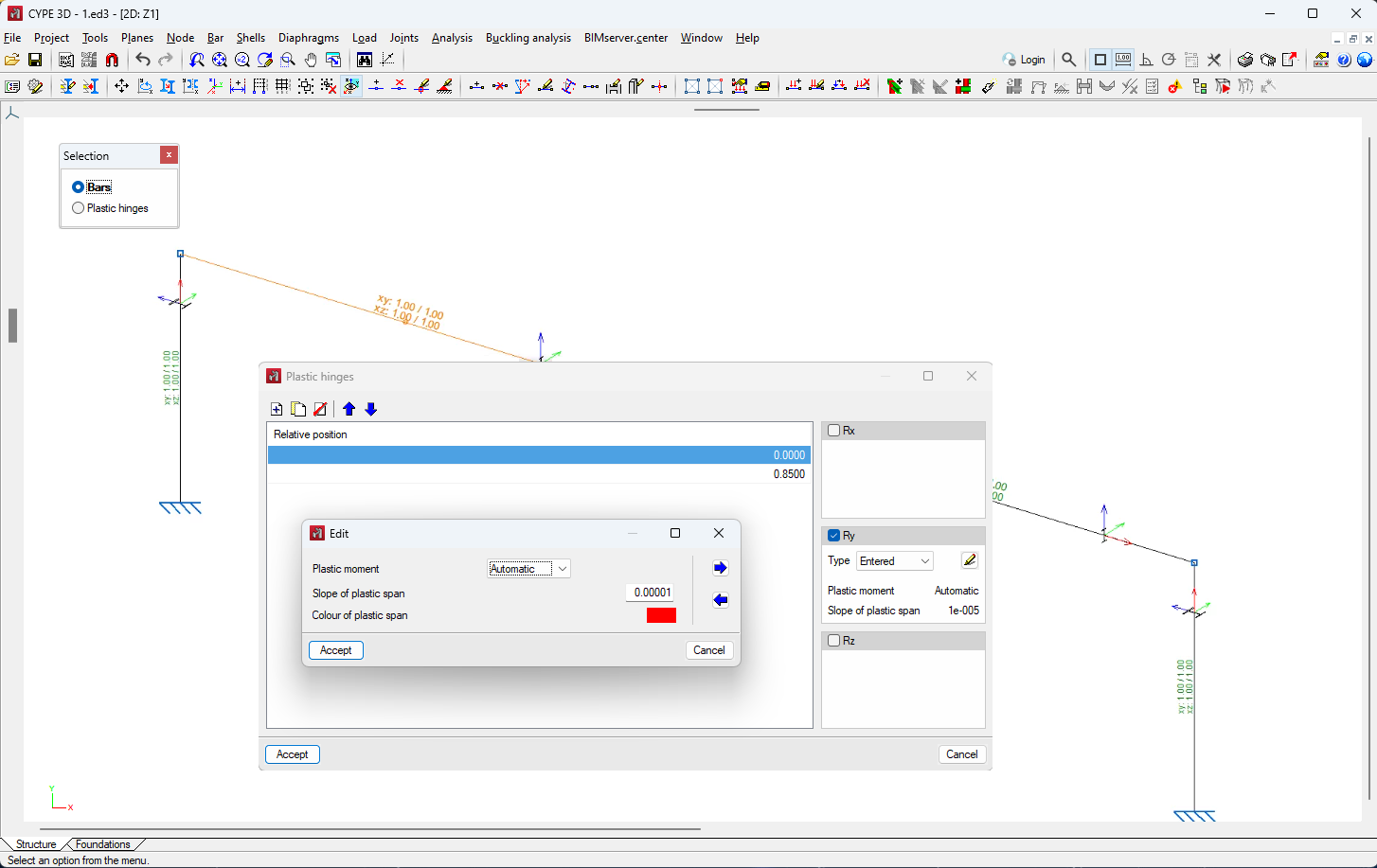
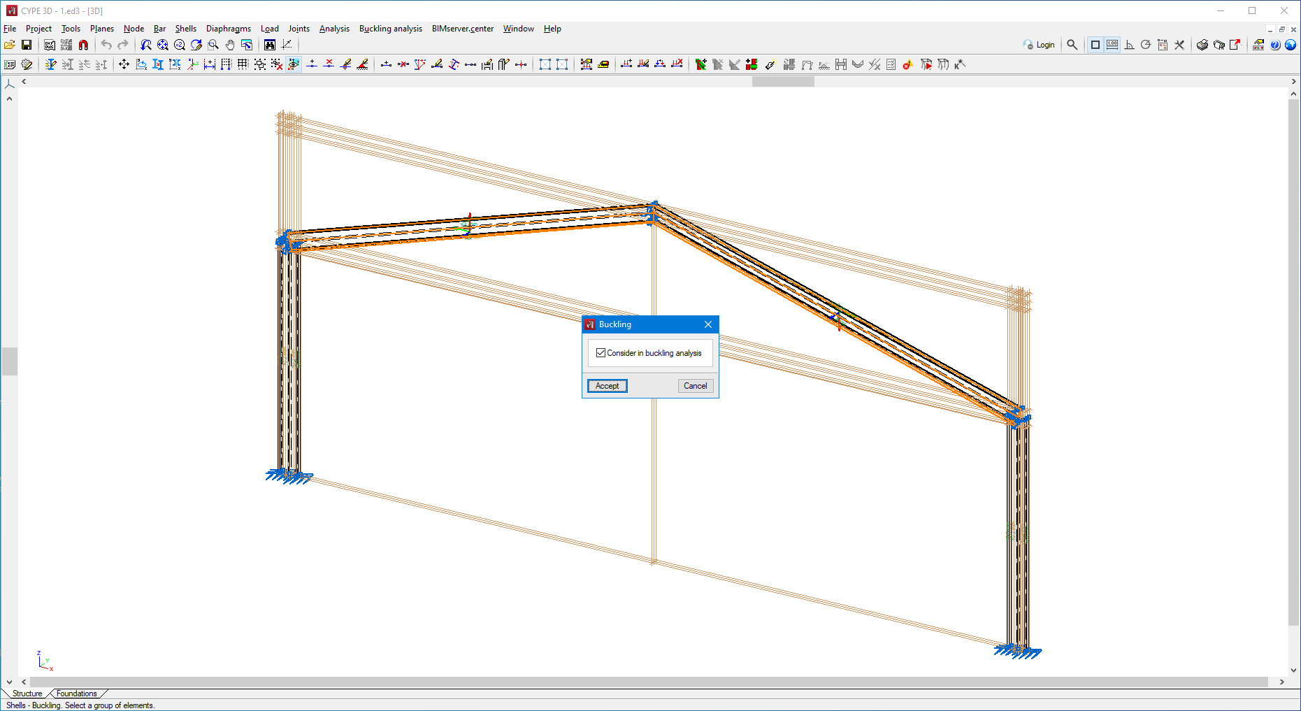
In the buckling analysis of each of the groups, all the elements marked with the "Consider in buckling analysis" option (Bar menu > "Buckling" option) and which also have one of the layers selected in the definition of the group assigned to them will be considered.
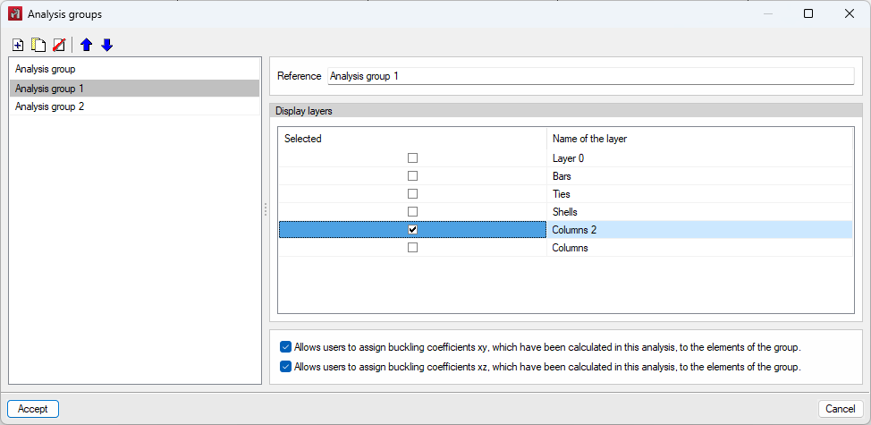
The consideration of groups for the analysis is optional. If no group is entered, the program will perform a single analysis considering all the bars and plates marked with the "Consider in buckling analysis" option. If a bar belongs to more than one group and an automatic assignment of its buckling coefficient in the xy, xz or both planes is carried out, it will be assigned the highest of all the coefficients analysed in the buckling analyses of the groups to which it belongs.
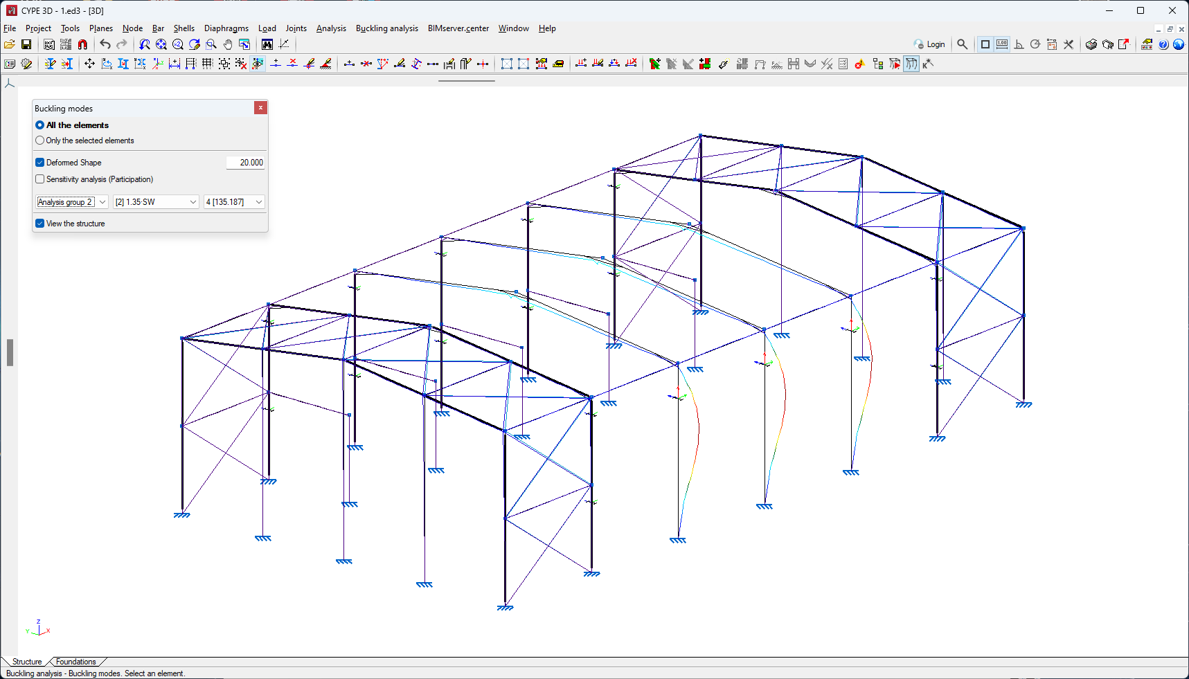
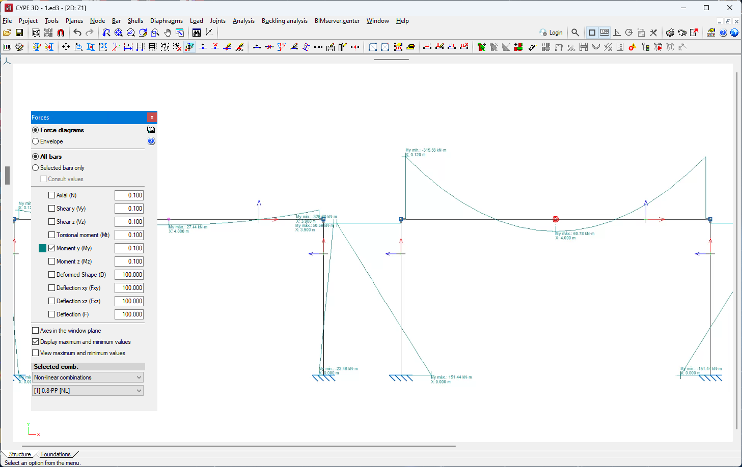
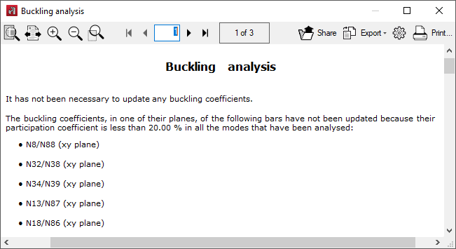
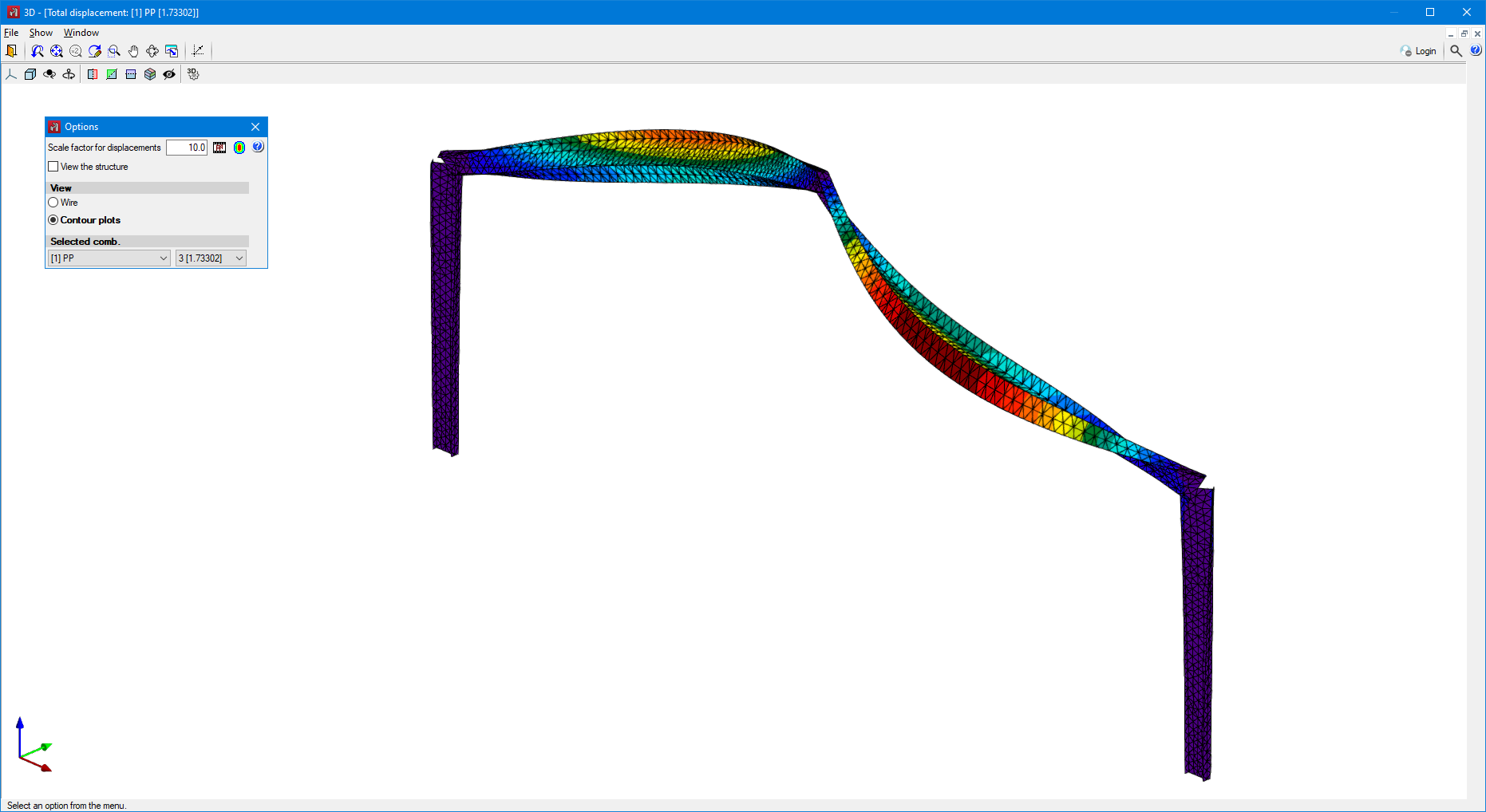
The buckling analysis results are displayed for the selected analysis group.