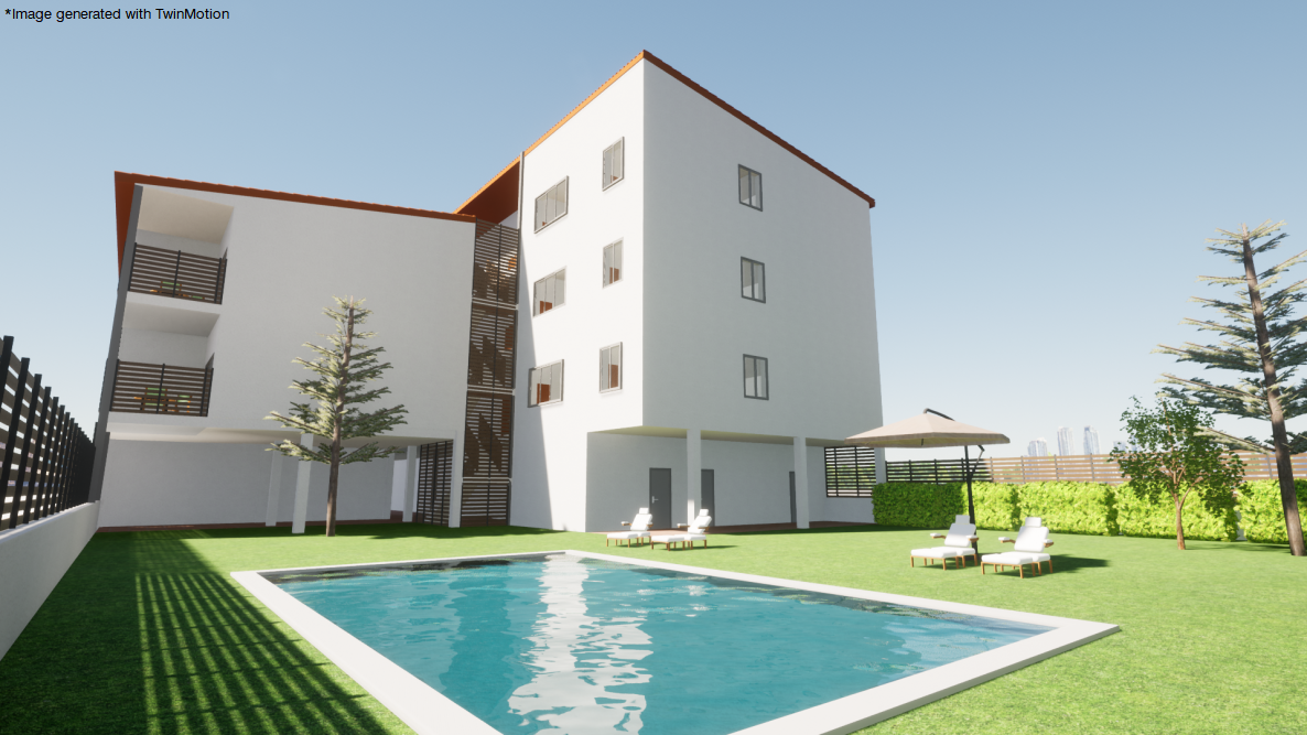
The interface of this submenu has been updated. It consists of the following options:
- Enter dimension lines
- Introduce sections (Sections at cut line)
- Introduce sections (Outside the drawing)
- Modify
- Delete


The interface of this submenu has been updated. It consists of the following options:
In previous versions, the construction elements that could be entered in CYPECAD were defined between groups ("Beam definition" tab > "Loads" menu). Now the possibility to enter "Parapets" has been implemented. Parapets are defined in the same way as the construction elements between groups, but instead of specifying the end group, the height of the parapet must be defined.
Parapets will not be included in seismic analyses, as opposed to partitions.
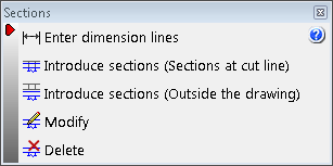
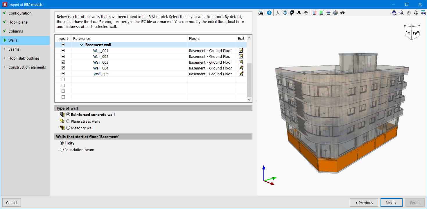
When importing a BIM project, elements whose "IfcWallTypeEnum" property is "PARAPET" shall be automatically marked to be imported as construction elements of the "Parapet" type. If they do not have this property, they can be marked manually in order to be generated correctly.
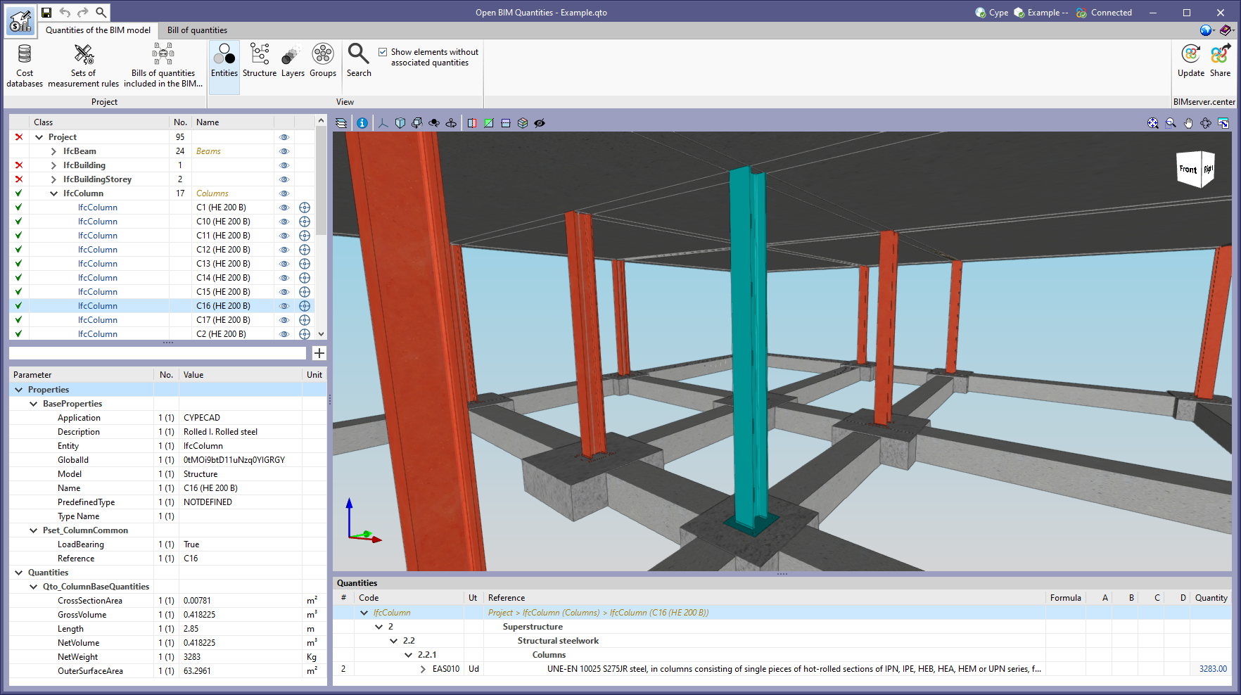
As of version 2023.b, CYPECAD exports the quantities of the IFC standard ("IfcQuantitySet") related to structural elements with steel sections to the BIMserver.center project. These quantities can be read by other applications integrated in the Open BIM workflow via the BIMserver.center platform.
For example, the Open BIM Quantities tool can use this information for generating the bill of quantities.
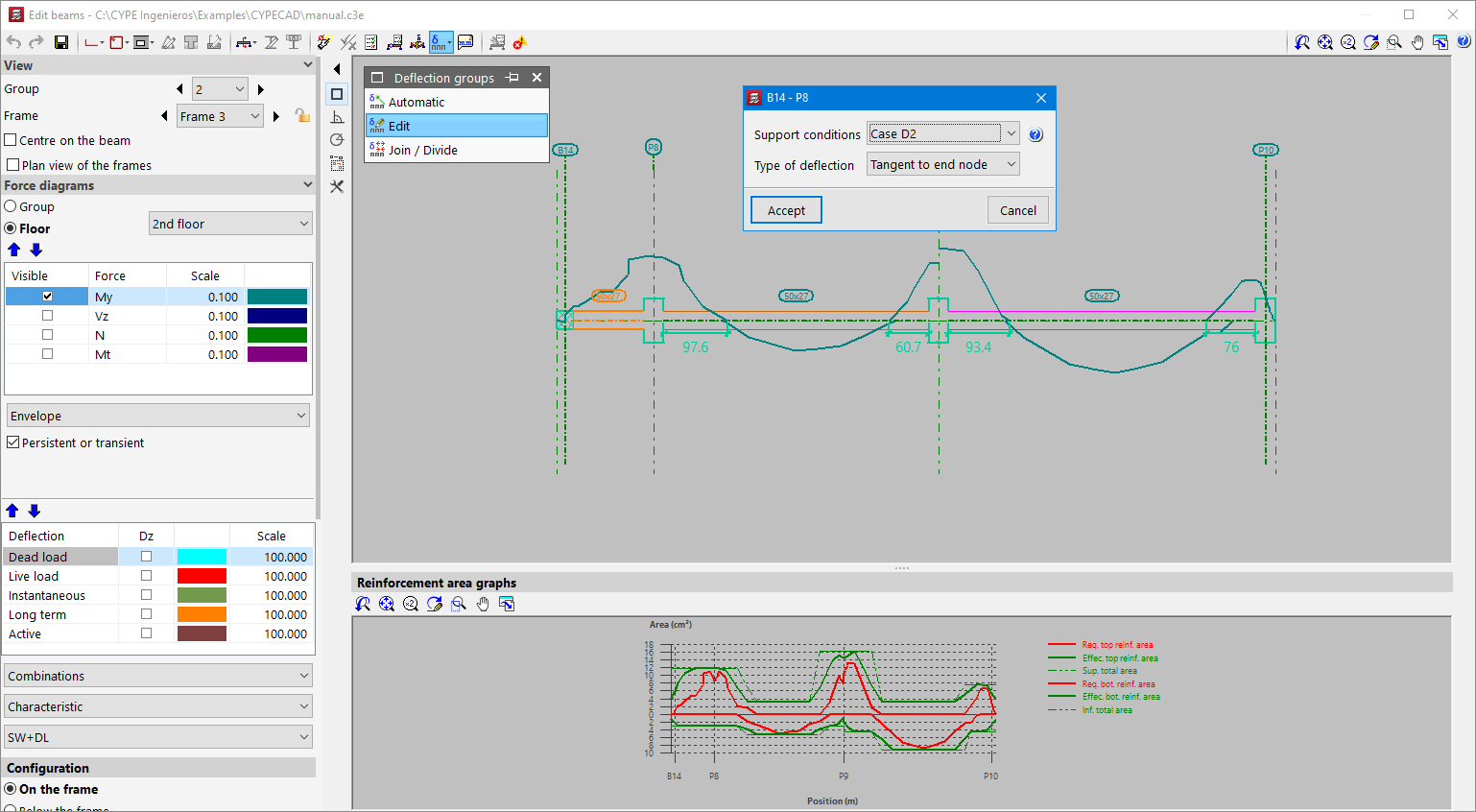
In version 2023.b, three options have been added for editing the deflection groups of beam frames. Up to this version, deflection groups were generated automatically and no changes could be made. These options are as follows:
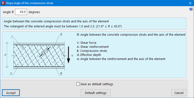
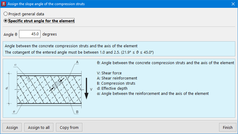
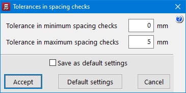
Two options ("Slope angle of the compression struts" and "Tolerances in spacing checks") and several improvements have been implemented in order to optimise the check and design of beams and columns. These options and improvements are available for the following codes:
These new options can be accessed via the “General data” panel:
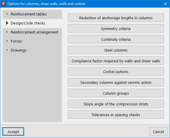
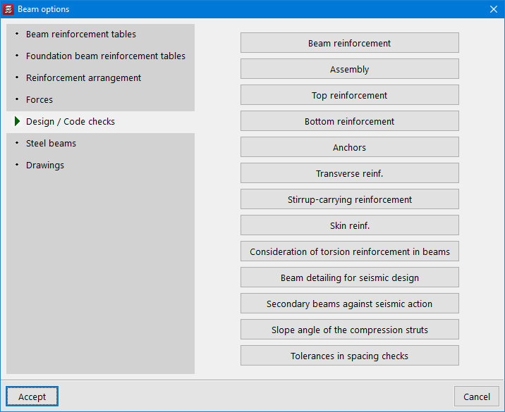
The new options and improvements are detailed below:

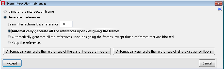
The “Beam intersections references” option has been added to the “Groups” menu of the “Beam definition” and “Results” tabs. These references can now be generated automatically according to the order of the frames.
For jobs created from version 2023.a onwards, this will be the default option. For jobs that have already been created, the order in which they were generated is maintained, but the "Beam intersections references" option can be used to change the order.
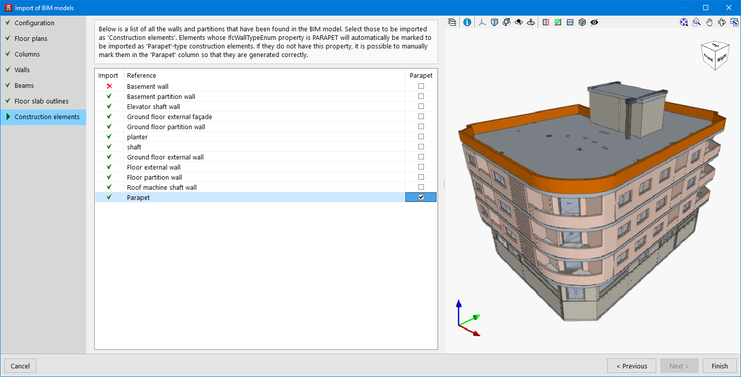
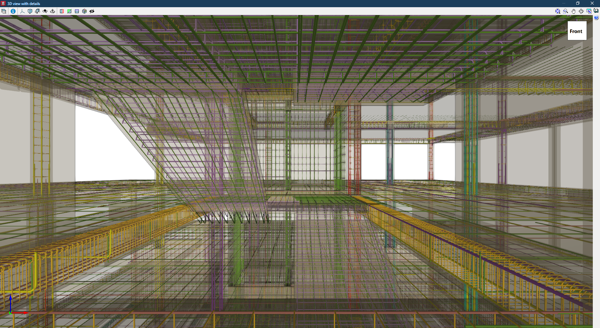
The rebars of shear walls and stairs can now be exported to the BIM model.
In the current version of the program, CYPECAD exports the reinforcement of the following types of elements:
This reinforcement can be viewed in the StruBIM Rebar program along with the reinforcement exported from StruBIM Shear Walls.
They can also be viewed in CYPECAD in the "Results" tab (Groups menu > 3D view with details).
As of version 2023.a, structural walls defined in a BIM project can be imported. This option is available both for projects modelled using our CYPE Architecture tool and for projects created with other BIM modellers.
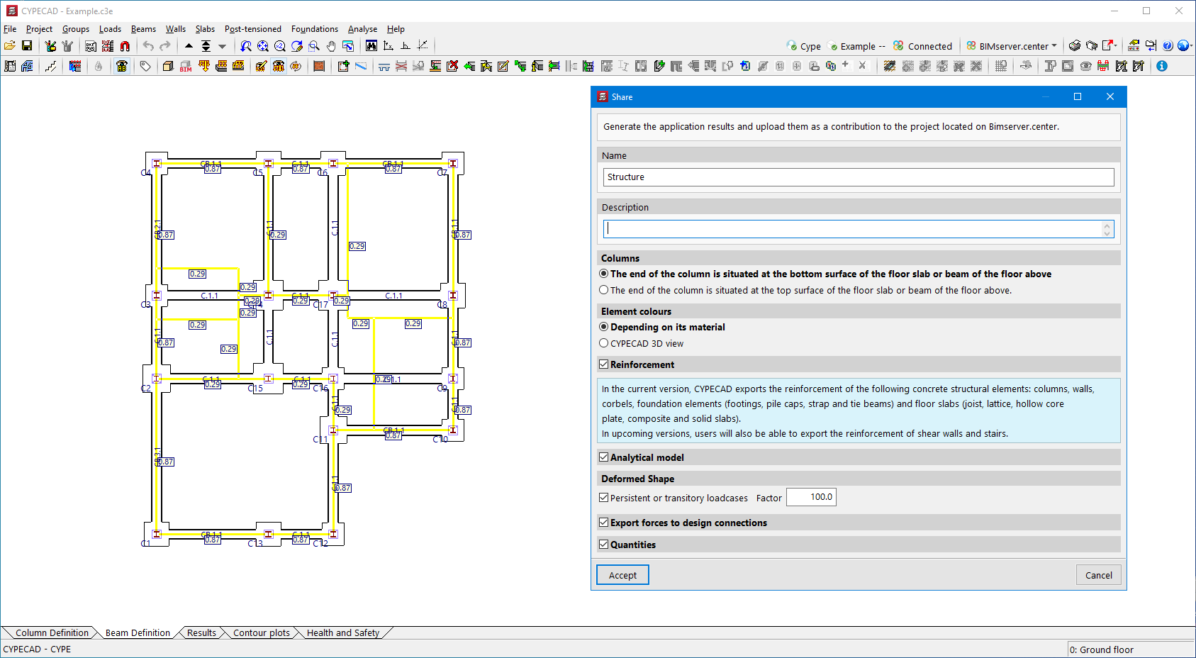
Version 2023.a of all CYPE programs that have the "Print/Save the current view" tool (usually all programs that display graphic information in a window) allows any generated 3D model to be exported in FBX format. This is one of the most common and accepted formats among rendering software (Twinmotion, Enscape, Sketchup+Vray, among others).
Exportation in FBX format is found in the dialogue box that opens when selecting the "Print/Save the Current View" button in any of the programs that include this tool. This feature allows users to export any element that is visible in the current window at that moment in FBX format (as well as elements that have been imported from other programs).