Eurocode 1: Actions on structures. Part 1-4: General Actions - Wind Actions. National Annex AN/UNE-EN 1991-1-4.
Implemented in CYPECAD and Portal frame generator.


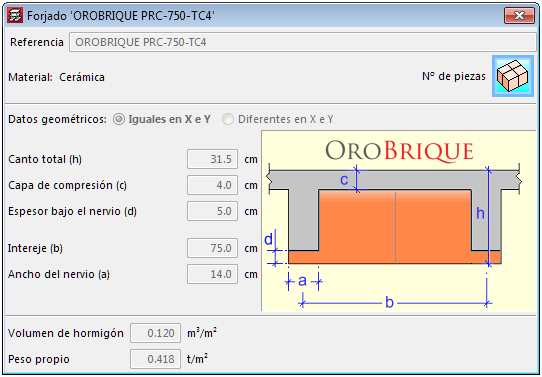
Waffle slabs with ceramic filler blocks belonging to the manufacturer: OROBRIQUE, have been implemented. The feature of these slabs is the ceramic part below the rib, which allows fixed building service elements to be installed.
The following types have been added:
These floor slabs are available for the French reinforced concrete code BAEL-91.
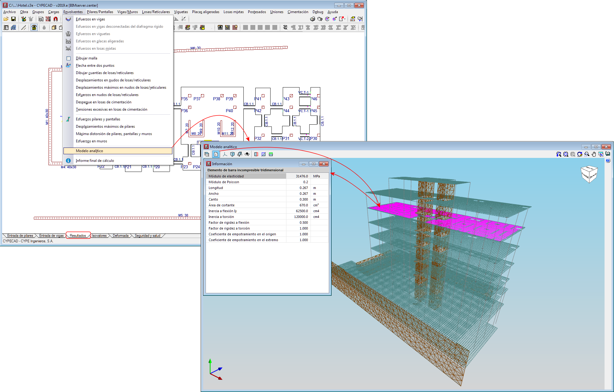
3D view of the analytical mode. New view
A 3D view of the analytical model has been included in the 2019.f version, which substitutes the old “3D model” view.
The 3D view of the analytical model can be accessed by going to the “Envelope” menu in the “Results” tab. This view is generated when the project is analysed and is always that of the last analysis.
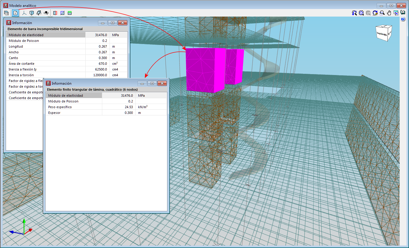
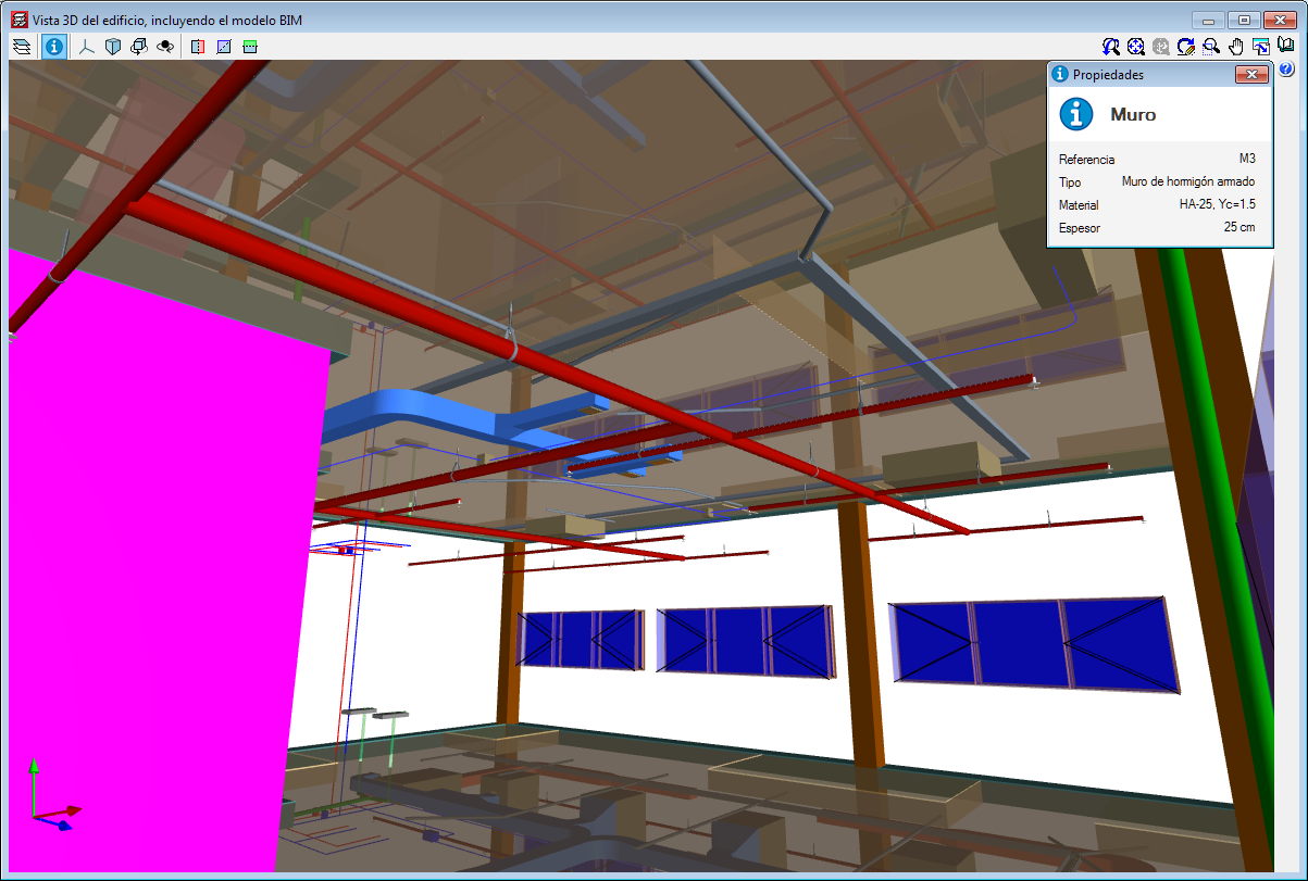
The 3D view has an “Information” tool that is available to users (located in top left hand corner), which displays the properties of the element that users have double clicked on, in a floating window. If users carry out this selection and press the “Ctrl” key at the same time, the floating window remains on screen when another element is selected.
3D view of the analytical model. Export to the BIM model
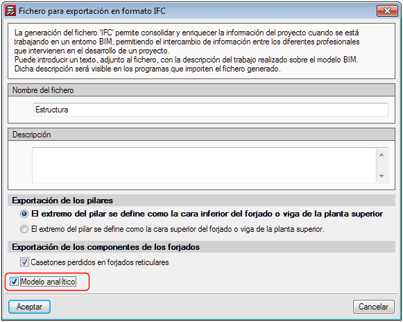
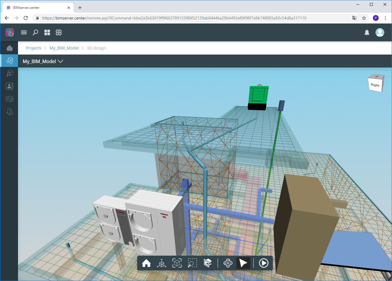
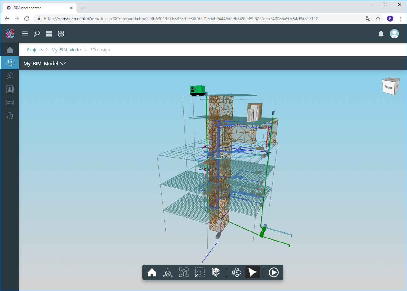
If the project that is being worked on in CYPECAD is linked to an Open BIM model located on the BIMserver.center platform, the new view of the analytical model is also exported to BIMserver.center.
To do so, the “Analytical model” option must be marked in the panel that appears when the information is exported from CYPECAD to the BIM model. This way, the IFC that is generated during the export process will contain the reference to the GLTF file that contains the 3D view of the analytical model containing the information of the elements it is composed of.
Therefore, it is now possible to consult the analytical model and the physical model of the structure using the 3D viewer of the BIMserver.center platform and also from the 3D views of the rest of the applications connected to the BIM model.
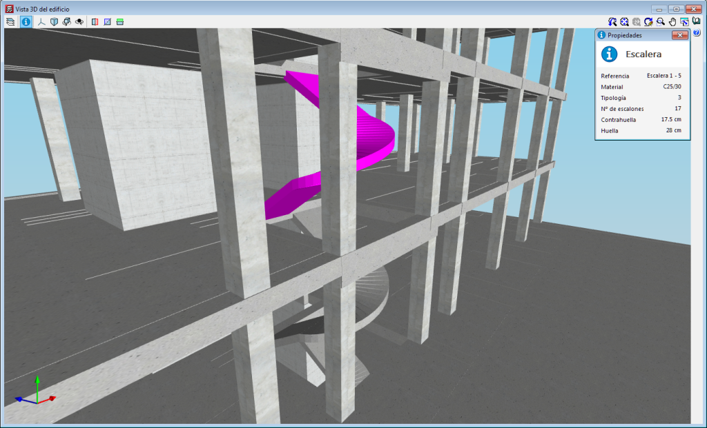
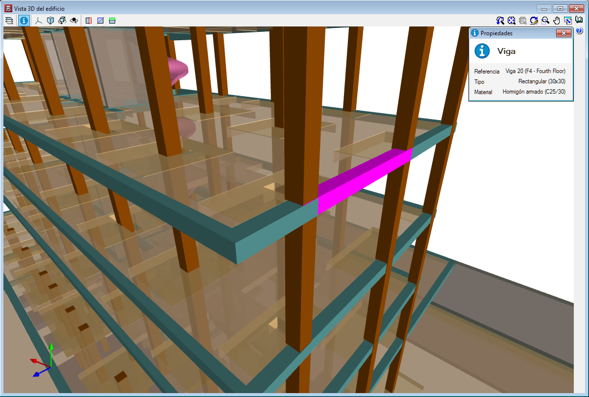
3D view of the structure. Information on the structural elements
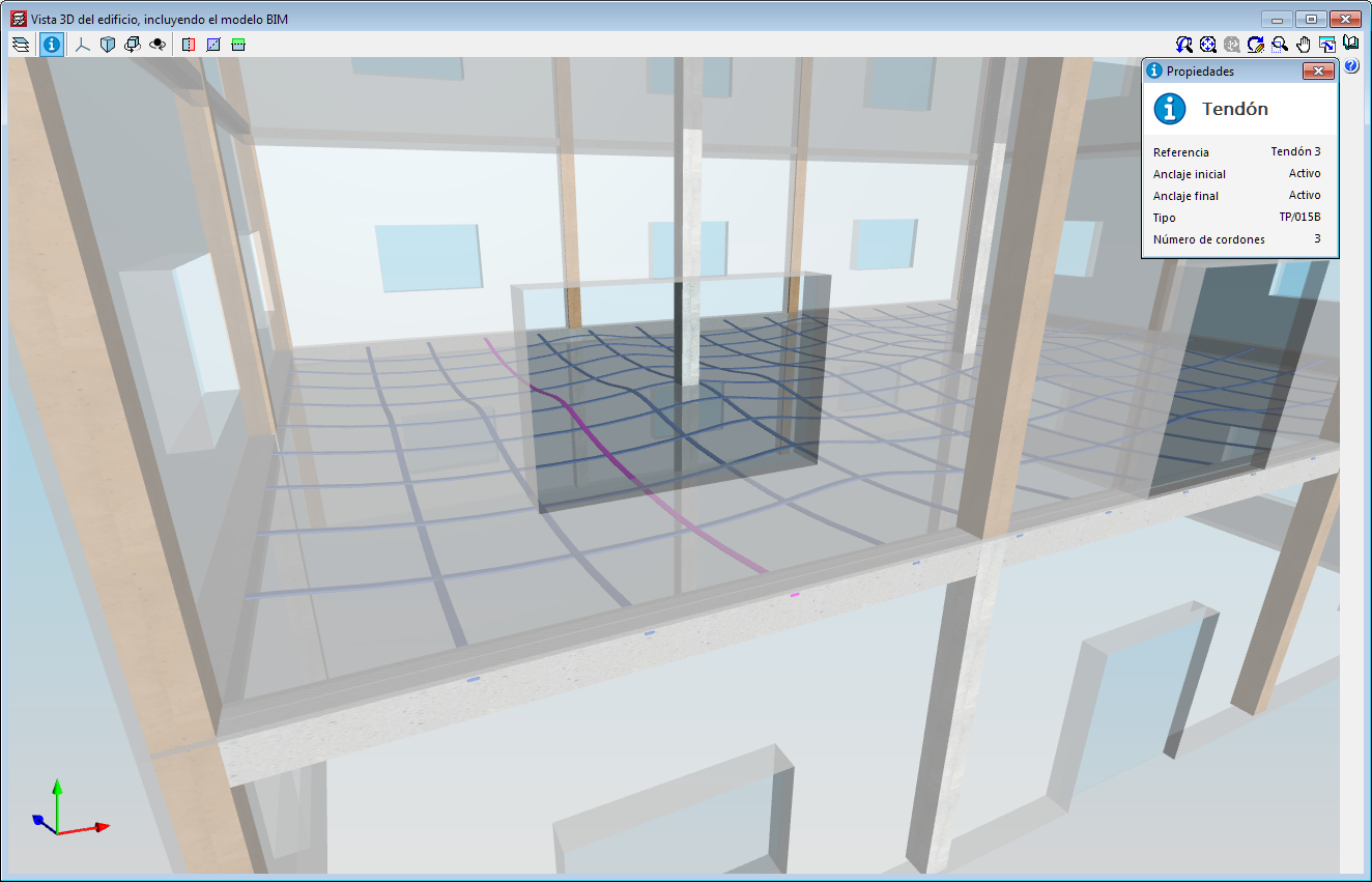
As of the 2019.f version, users can consult the information of the structural elements introduced in the 3D view of the structure shown in CYPECAD, in the 3D view of the BIM model (GLTF) or in the 3D view of the other applications connected to the BIM project. It includes the information on slabs, beams, sloped beams, foundation elements, walls, stairs and post-tensioned tendons.
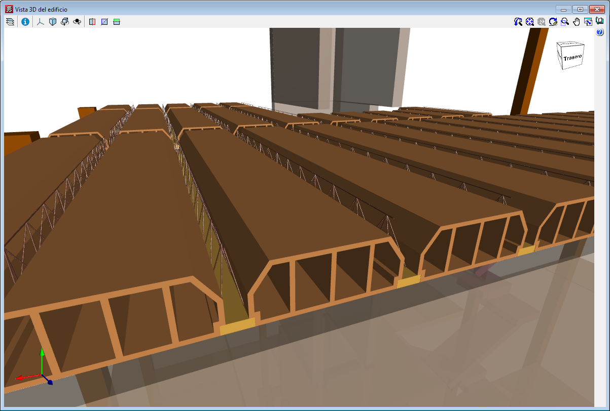
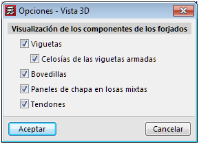
3D view of the structure. New structural elements in the 3D views (joists, forms, composite slab decks and post-tensioned tendons
The 2019.f version provides users with the possibility to include the following structural elements in the 3D view of the structure of CYPECAD and in the 3D view that is exported to the BIM model:
To view these elements in the 3D view of CYPECAD, users must select them in the “Groups > Options - 3D View” menu. A panel appears when the export process is carried out, where users can select the elements.
The “Wind load justification report” has been implemented in the 2019.f version for the following codes:
This report was implemented in previous versions for other design codes and will continue to be implemented for others progressively.