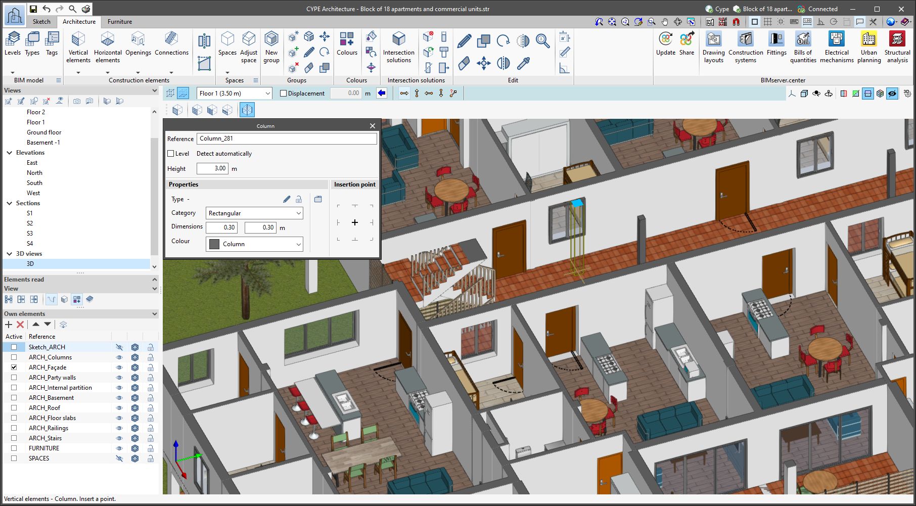
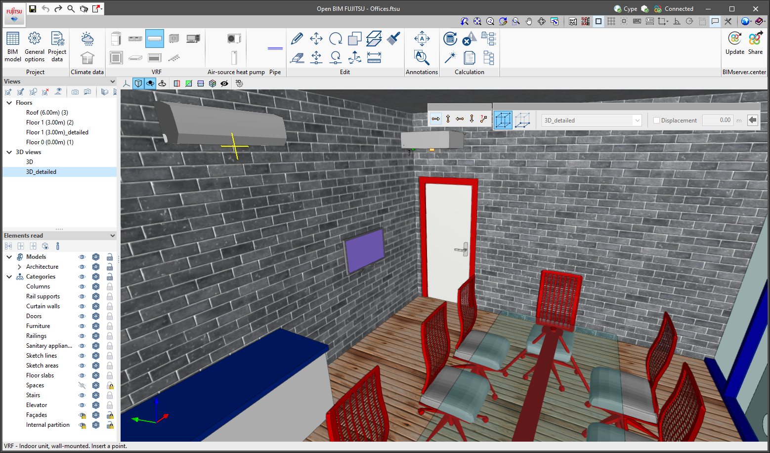
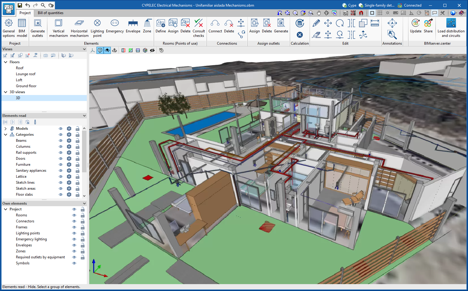
A new tool has been implemented in the user interface that is common in Open BIM applications with a 3D working environment. Now, the management of the elements from the digital model of the building, which comes from the associated BIMserver.center project, is carried out from the "Elements read" menu located in the left sidebar of the application.
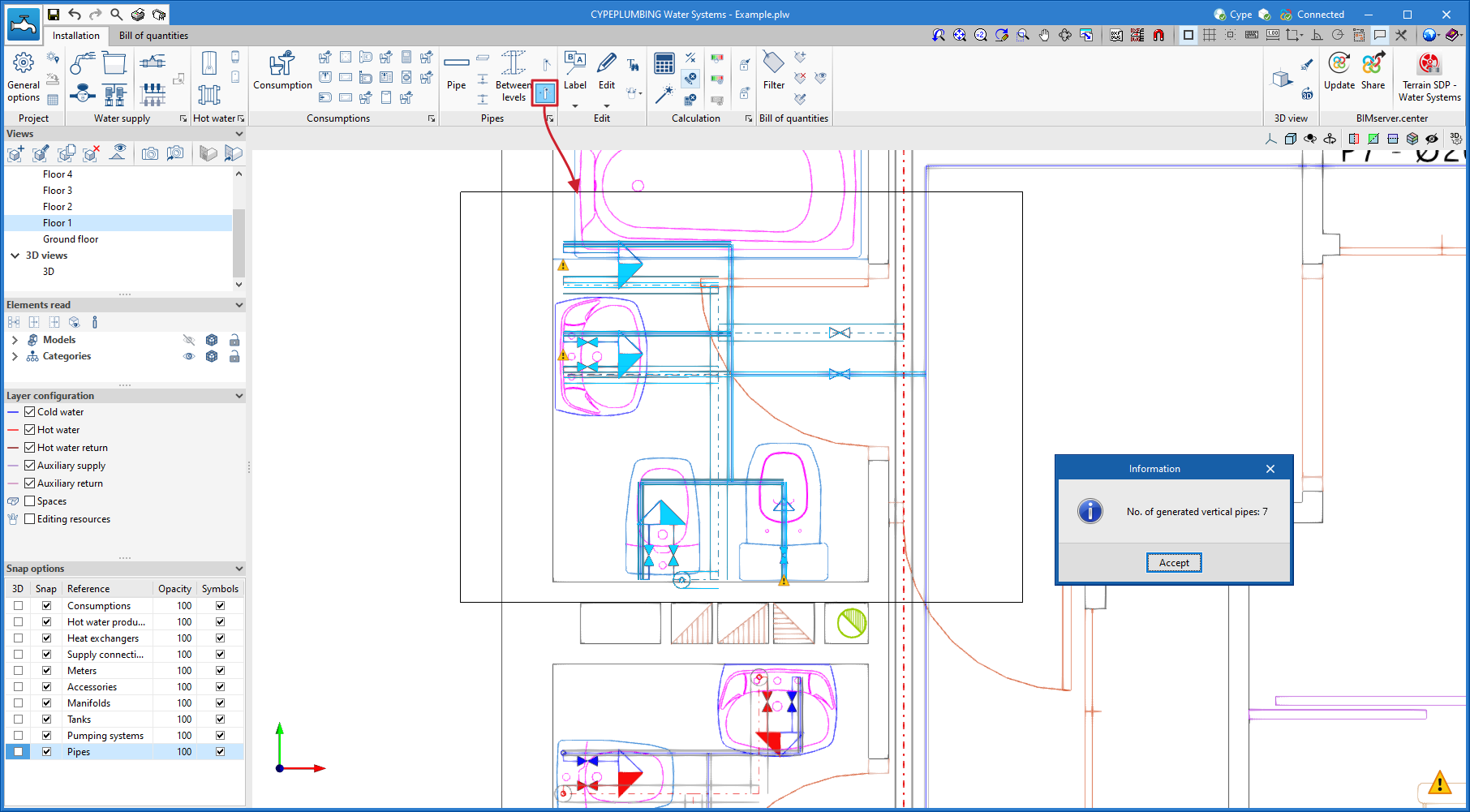
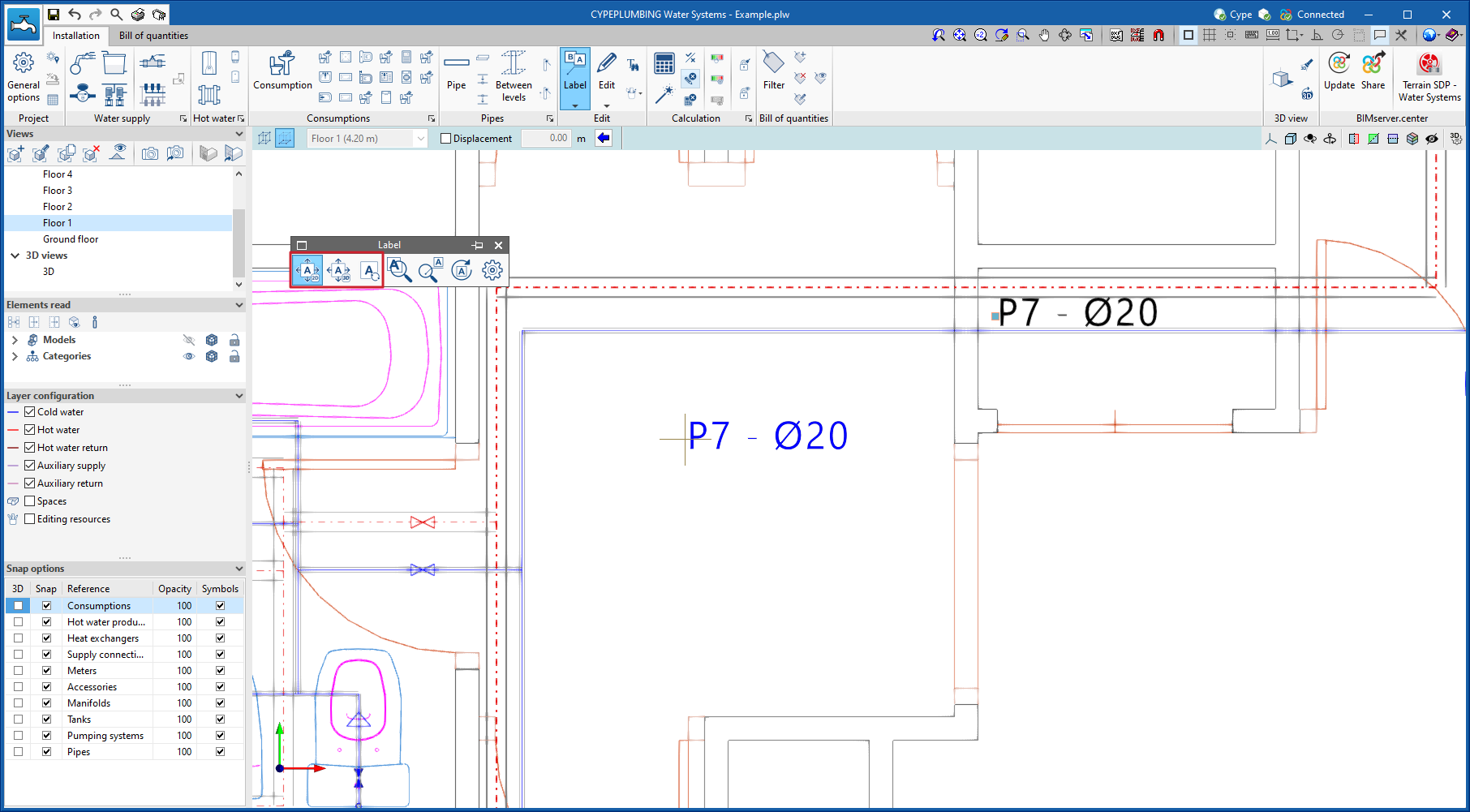
The elements read are structured in the form of a tree based on two classification types: "Models" and "Categories". The organisation by "Models" allows users to inspect each contribution linked to the job and each associated 3D model within it. On the other hand, the "Categories" group the "Elements read" into families according to their features. Next to each tree component, three buttons are displayed to control the visibility, the display mode (solid, transparent or wire) and the object snap. It should be noted that the organisational settings applied to the organisation by "Models" prevail over those indicated by "Categories".
Applications can have default visibility and object snap settings when creating a new view. Furthermore, when entering new components with the tools in the program, the application itself can force the activation or deactivation of the visibility and object snaps of certain categories. When this happens, a yellow padlock will be displayed next to the set options. When users finish using the tool, the tree will return to its original state.
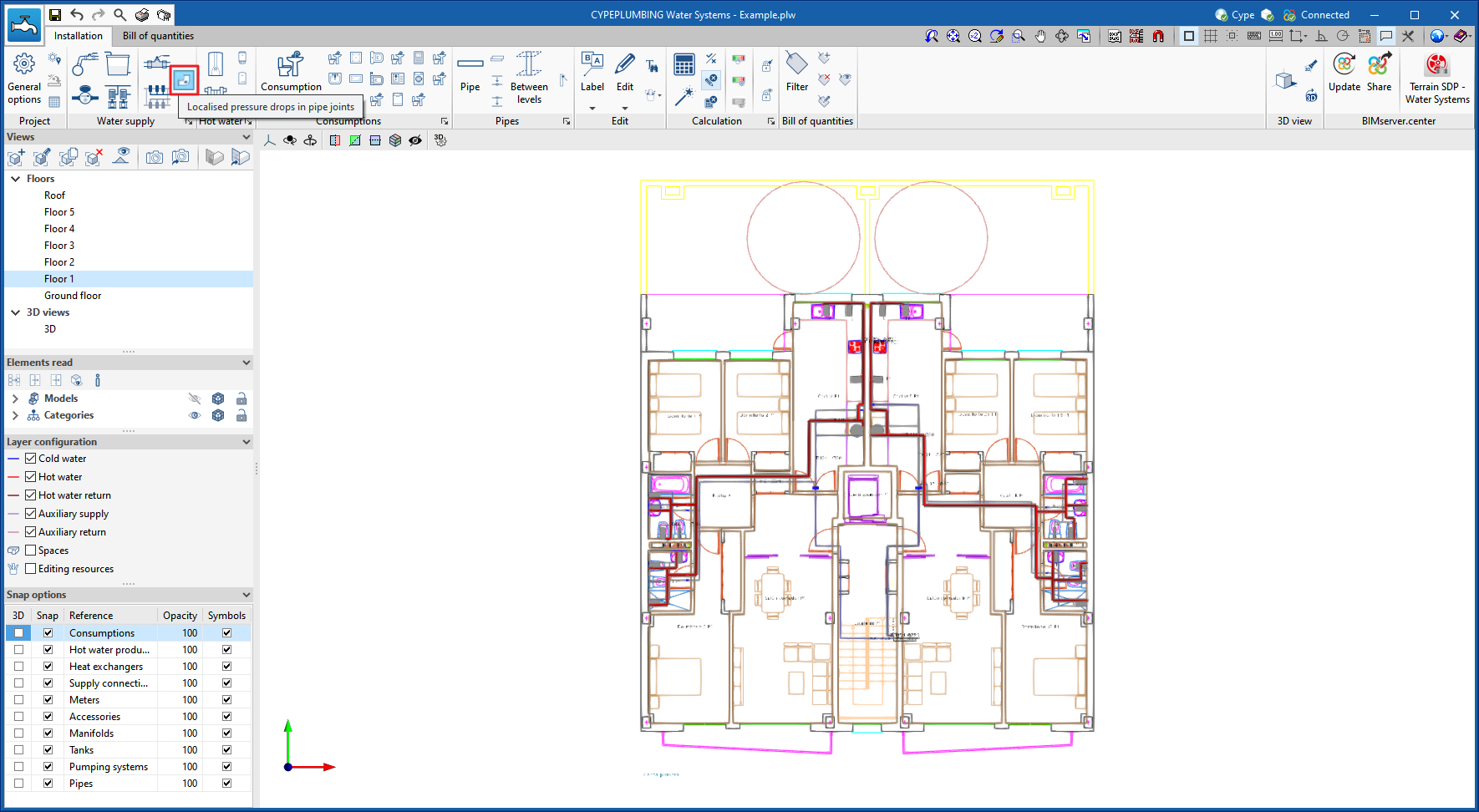
In previous versions, the management of the visibility of BIM project models was carried out in the configuration panel of a view. As a consequence of this improvement, editing is now managed from the "Elements read" menu in the left sidebar and has therefore been removed from the previous location. However, in the editing panel of a view users can indicate whether the view should have its own configuration for viewing these elements or whether it should use the general configuration of the job. For this purpose, the "Use a specific view configuration for the view" option has been added. When this option is active, the "View" text will appear in the "Elements read" menu.
In addition to the component tree of the external models, the "Elements read" menu includes a toolbar with a group of buttons that allow the following actions to be carried out:
- Isolate selection
Allows elements from the 3D model to be isolated. Users can select the elements of the 3D model that they wish to isolate and when right-clicking on them, the rest of the elements from the model will disappear.
- Hide
Allows the selected elements to be hidden. Users can select the elements from the 3D model that they wish to hide and by right-clicking on them, they will disappear.
- Show all
Shows all hidden elements.
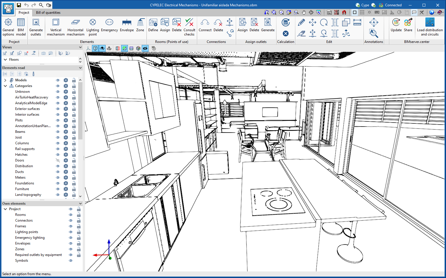
- Aspect
Allows users to choose between normal drawing or monochrome drawing.
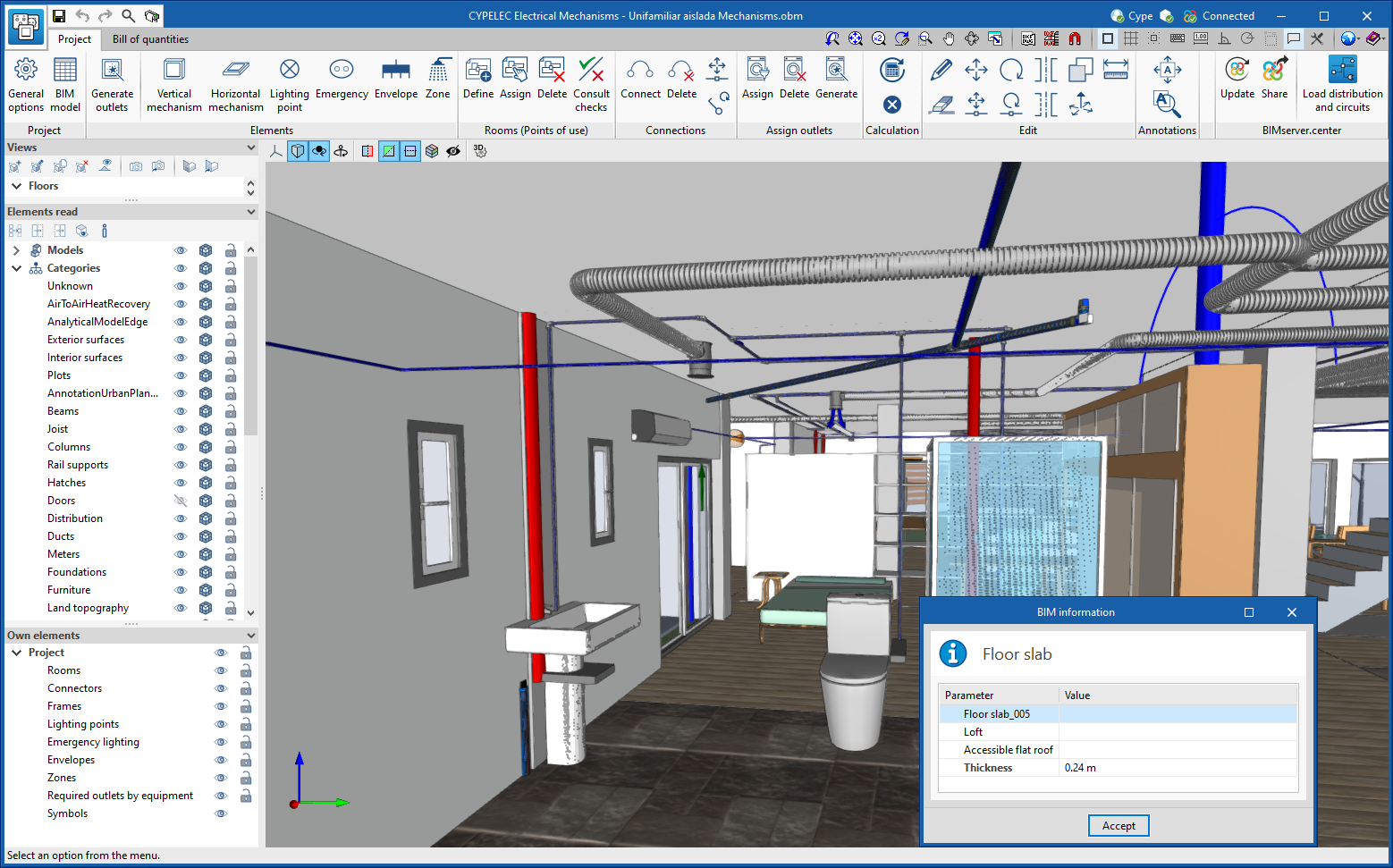
- BIM information
Displays a panel showing the attributes associated with the selected component.
In version 2023.a, the management of visibility and object snaps of external elements is available in the following CYPE Open BIM applications:
- CYPE Architecture
- CYPELEC Distribution
- CYPELEC Electrical Mechanisms
- CYPELEC PV Systems
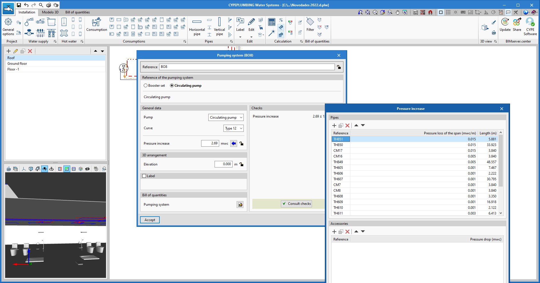
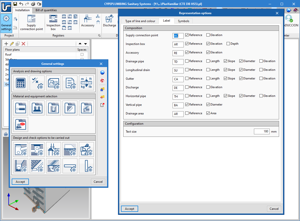
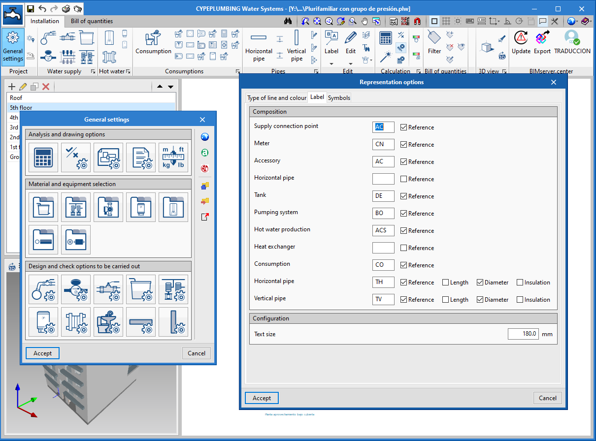
- CYPEPLUMBING Water Systems
- CYPETHERM RE2020
- CYPEURBAN
- Open BIM Analytical Model
- CYPE Construction Systems
- Open BIM COVID-19
- CYPE Lightning
- Open BIM Sampling
- Open BIM Site