As of version 2023.g, applications with a 3D work environment can include a new feature that allows users to associate the elements of their model with levels (the programs that have this utility in version 2023.g are listed at the end of this new feature). The levels can correspond to the floors of a building or any other reference plan required for the model.
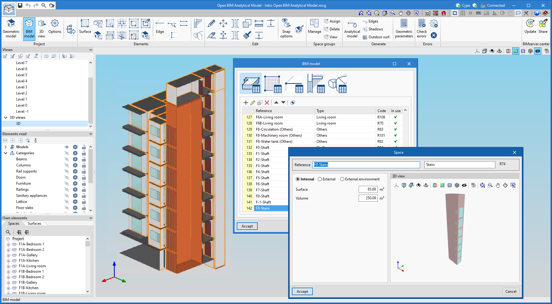
The level management menu is included in the applications by means of a dockable window. In this panel, there is a drop-down list with the buildings and levels defined in the model, as well as the available options (create, edit, delete, assign, etc.).
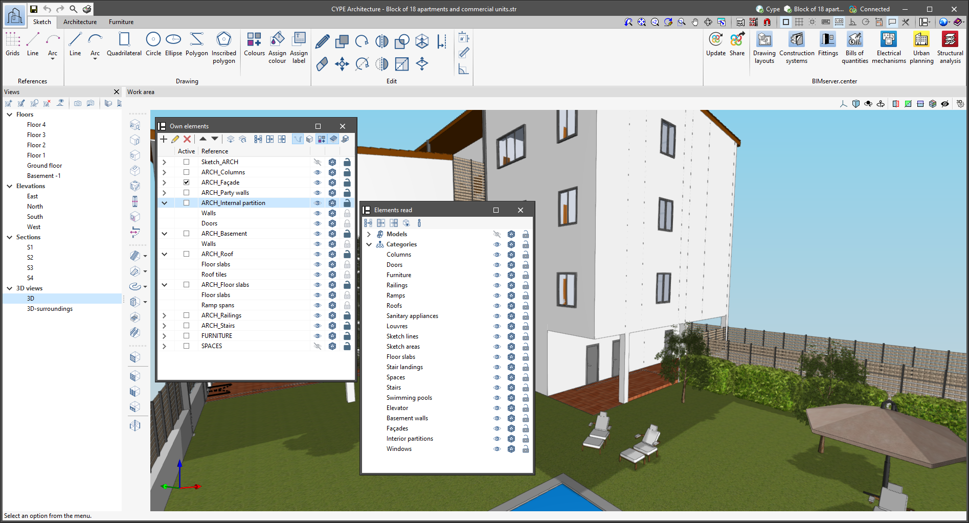
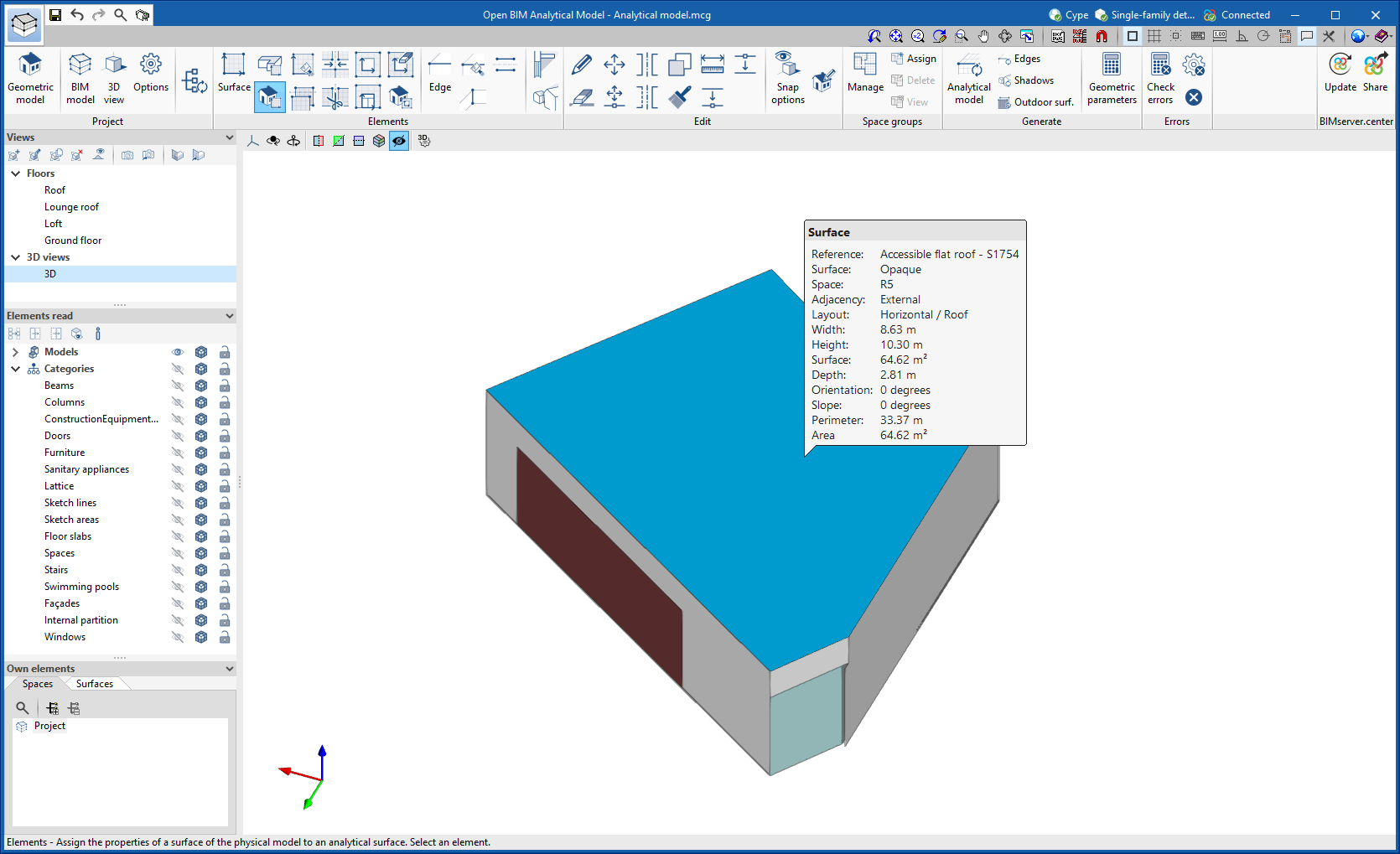
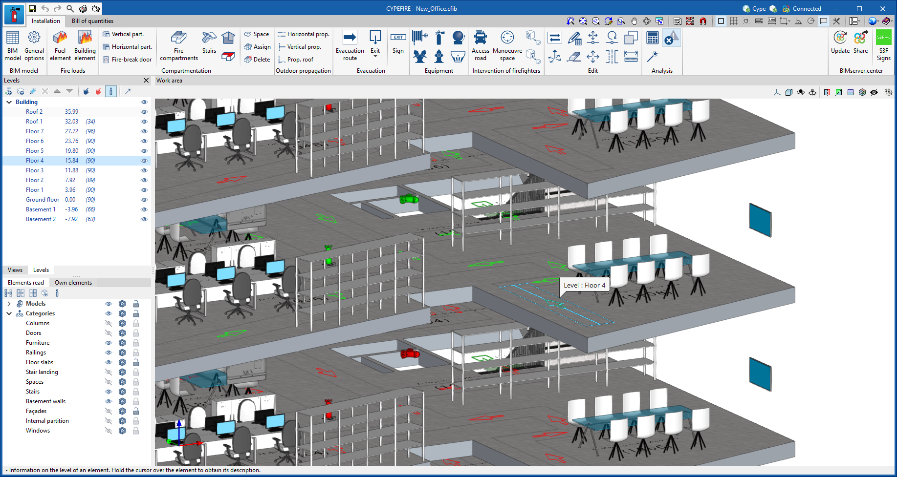
The options in the "Levels" window allow new buildings and levels to be entered in the model. Levels must be defined within a building. Next to each level, we can see its elevation and, shown in brackets, the number of associated model components. Their visibility in the work area can also be activated or deactivated.
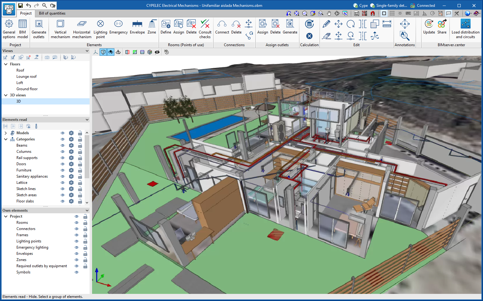
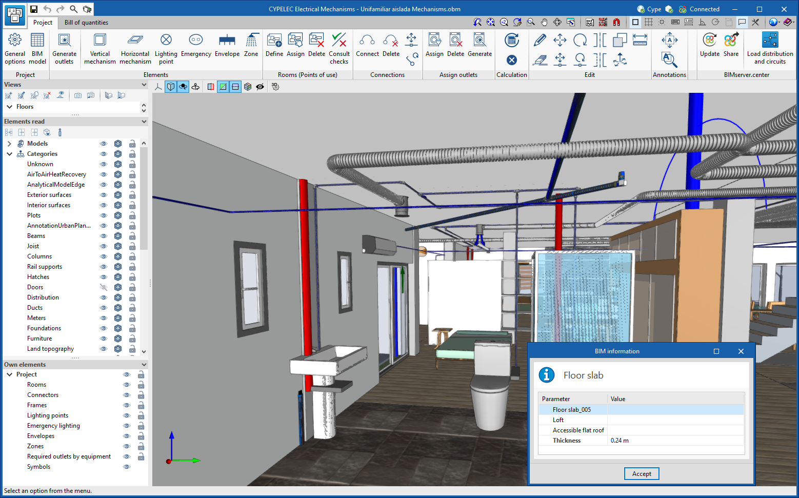
Using the "Assign elements to a level" option, we can select components of the model from the work area and associate them with the level selected in the list. The "Unassign elements to a level" option allows the reverse operation to be carried out. To help users when using these tools, the elements that belong to the selected level will be shown in green and those that belong to another level will be shown in red. The "Information on the level of an element" option is also available, with which it is possible to inspect an object from the work area and obtain its current level. Finally, the "Automatic level assignment" option associates the components of the model to the defined levels automatically. To do this, the geometry of the element is analysed and the level immediately below it is searched for.
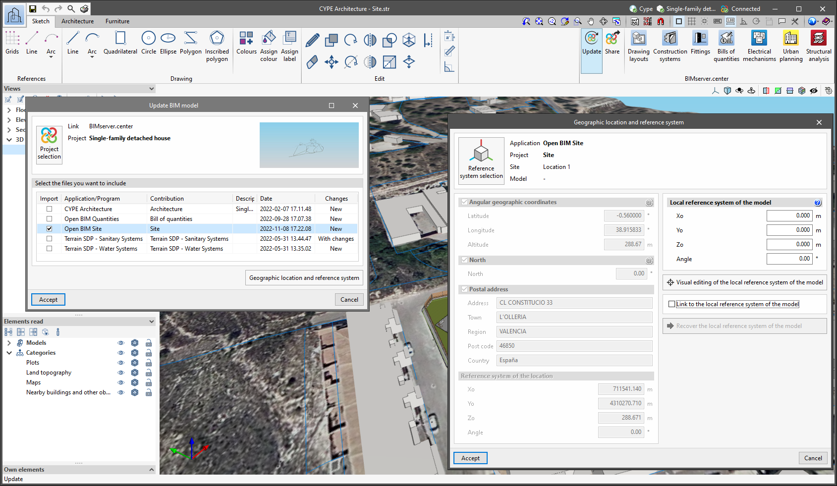
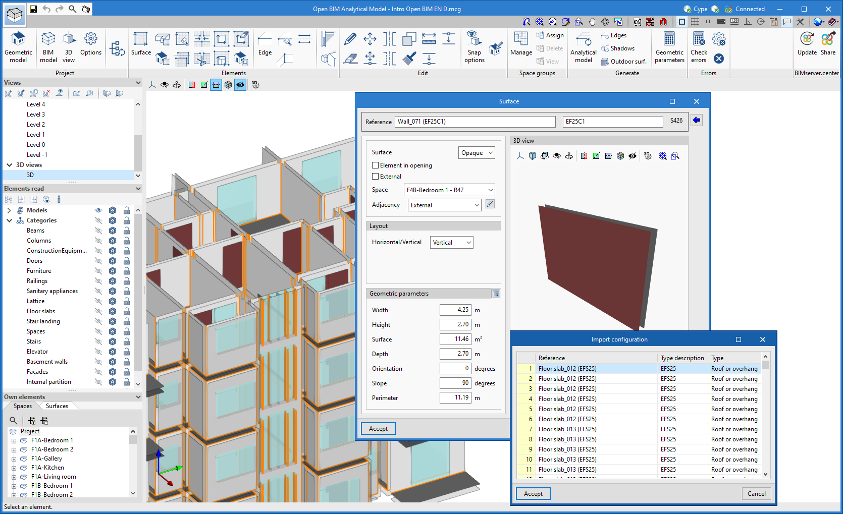
When linking to a BIM project, the application can read the buildings and levels of the contributions. These will be listed in the "Levels" window in blue and we can assign model components to them. To avoid congruence issues between contributions, buildings and levels that have been read from the BIM project cannot be edited.
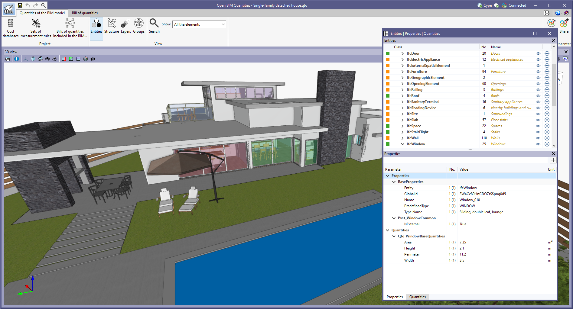
The levels are exported in IFC format via the "IfcBuildingStorey" entity. As this is an entity included in the standard, applications from other manufacturers that work with IFC files can read the levels and their relationship with the components of the model.
In this 2023.g version, the level management window has been included in the following applications:
- CYPEFIRE
- CYPEFIRE Hydraulic Systems
- CYPEHVAC
- CYPELEC Distribution
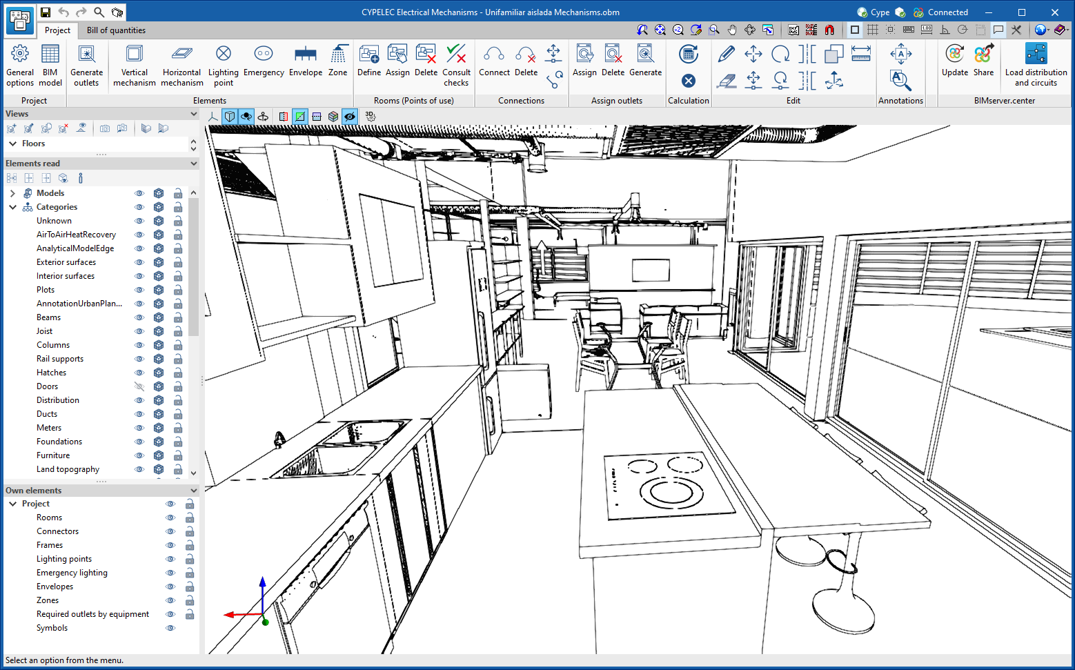
- CYPELEC Electrical Mechanisms
- CYPELEC PV Systems
- CYPEPLUMBING Water Systems
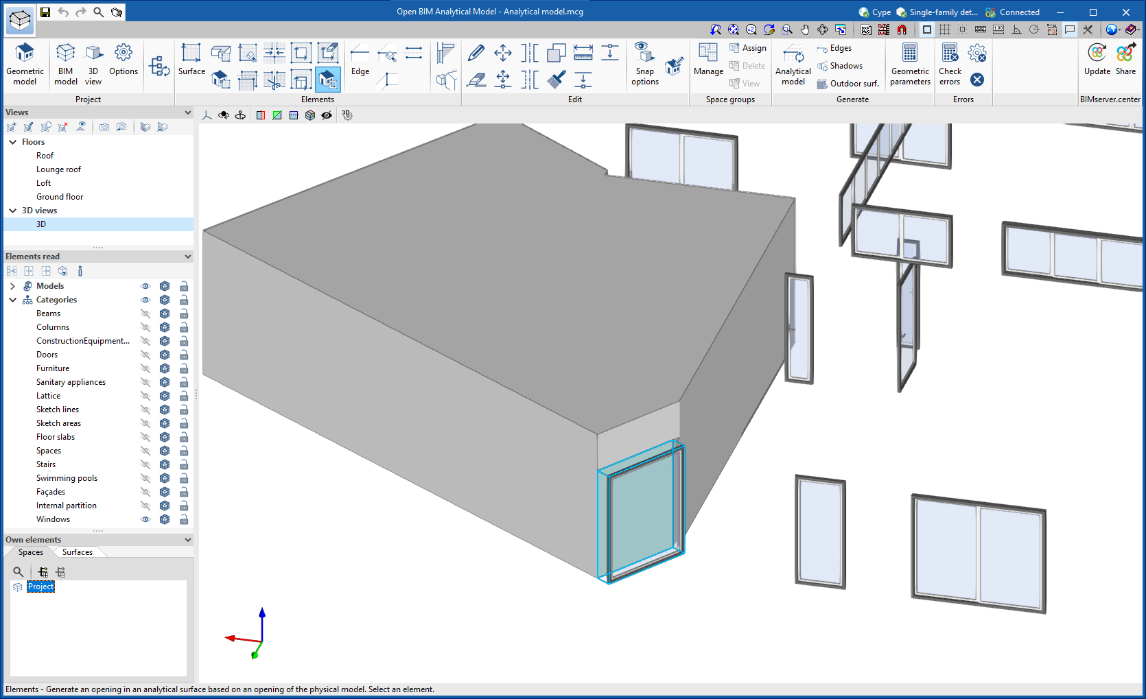
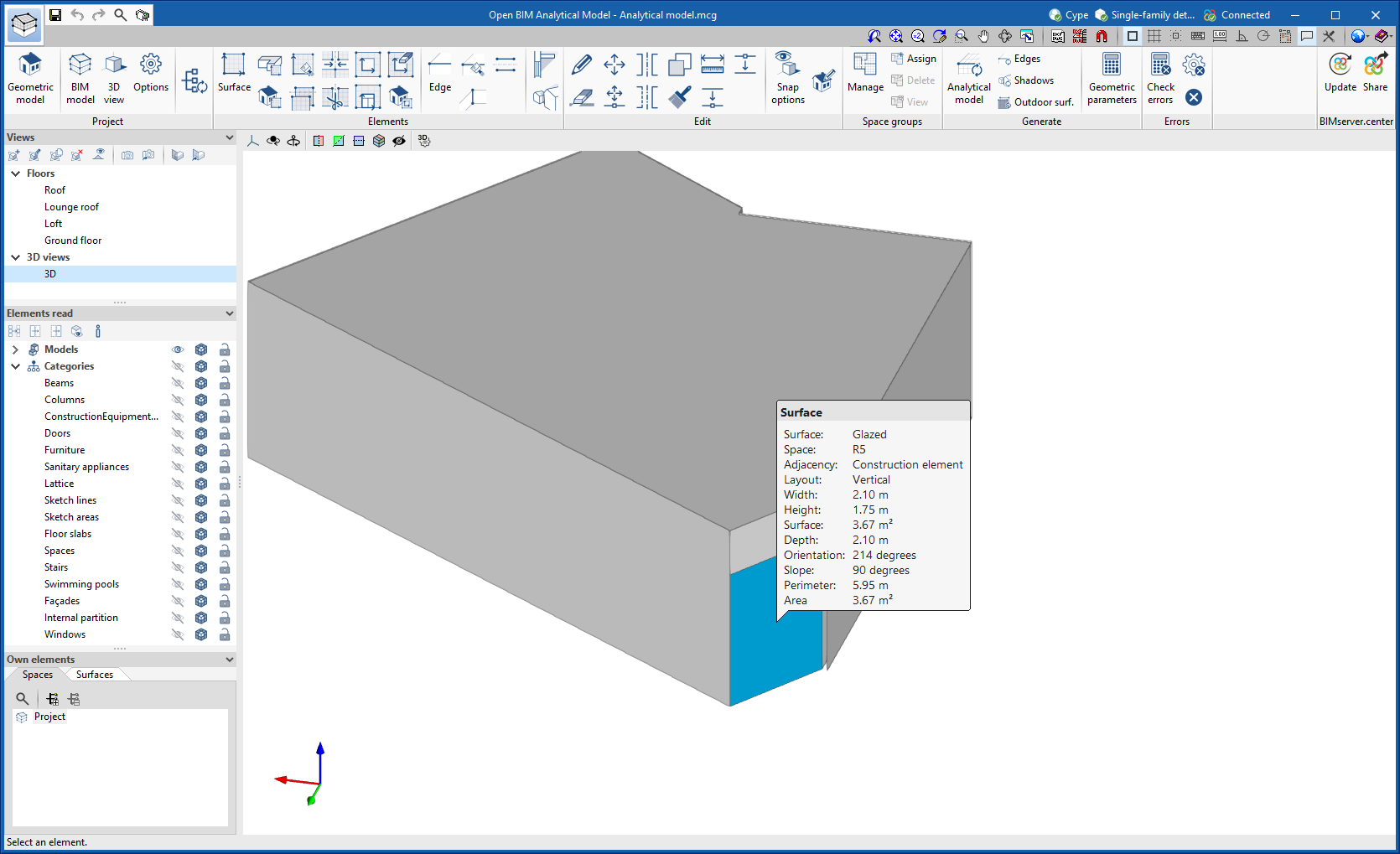
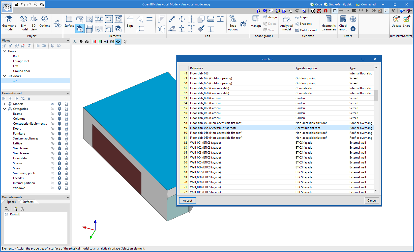
- Open BIM Analytical Model
- CYPE Lightning
- StruBIM Rebar