Update history​​

Open BIM Site

As of version 2022.g, the following tools from the "Edit" menu of the toolbar can be used on the topographic surfaces of the model:

  • Edit
  • Copy
  • Delete
  • Move a group of elements
  • Rotate a group of elements
  • Symmetry (move)
  • Symmetry (copy)
  • Measure

In order to be able to use the reference to objects on topographic surfaces, the "Capture" option has been added to the components list of the site model to capture this type of elements.

As a consequence of the computational cost of triangulating topographic surfaces, a tool has been added to simplify the number of points they contain and thus increase the performance of the application. This option is available in the project's table of topographic surfaces, available from the application's toolbar.

Once the simplification process has been completed, users are advised to review the result and increase its accuracy by editing the topographic points if necessary.

The "Type" column has been added to the project's table of topographic surfaces, available in the application's toolbar. In this new field, users can indicate whether the surface has either a "Mesh" or a "Grid" type definition. A "Grid" type topographic surface is defined by points arranged on the basis of a grid, whereas a "Mesh" type topographic surface is composed of vertices that are arranged without an organised structure. "Grid" type surfaces are more efficient when represented on the drawing area of the program, as the triangulation process has a lower computational cost. However, the points that make up this type of surface cannot be added or edited from Open BIM Site.

Along with the type of the topographic surface, the number of points that define it is also displayed.

The "Topographic surface" column has been added to the project maps table, available in the application's toolbar. For each map, a topographic surface can be selected where the map will be projected and displayed in the drawing area as a texture. If the "Without associated surface" option is selected, the map will be drawn at zero level, as in previous versions of the application.

A button has been added to the project's topographic surface table, available in the application's toolbar, for exporting the selected surface to a points file. The export format is a comma-delimited value file with the X, Y, Z coordinates of each point on each line.

As of version 2022.g, the points forming the topographic surfaces of the project can be modified. For this purpose, the following options have been added to the application's toolbar.

  • Add points
    It allows the user to select an existing topographic surface and add new points to its configuration.

  • Delete points
    It deletes one or several points belonging to the topographic surfaces of the model.

  • Move points
    It allows the user to edit the position of one or several points belonging to the topographic surfaces of the model.

  • Edit points
    It allows the user to edit the elevation of one or more points belonging to the topographic surfaces of the model.

The "Add points", "Delete points" and "Move points" tools can only be used on "Mesh" type topographic surfaces. "Grid" type topographic surfaces, usually imported from Web Coverage Services (WCS), can be transformed into meshes using the tool for simplifying surfaces (see new feature "Simplifying a topographic surface").

As of version 2022.f, Open BIM Site allows a topographic surface to be entered by placing topographic points on the work area. To do this, the "Define using points" button has been added within the "Topographic surface" group available in the application's toolbar.

Once the points have been entered, the application will automatically generate the surface and it will be added to the list of the project's topographic surfaces.

The new snap, "Fictitious intersection", has been included, which improves object snap tracking as it is able to detect possible intersections between objects that are at different heights.

This tracking makes the design more manageable and results in a more organised object distribution.

Currently, Open BIM applications with a 3D work environment have a tool window where the introduction mode of the model components can be configured. As of version 2022.c, when selecting "3D mode" it will no longer be necessary to specify the workplane nor the displacement value. Therefore, these parameters are left for the "2D mode", thus eliminating the duplicity that was present with both methods when entering or editing the position of elements that do not refer to other objects.

The interface for selecting the reference system of the job available during the linking process with the BIMserver.center platform project has been modified. Now, via the "Reference system selection" button located at the top of the window, the base reference system to be used is chosen. This displays a tree with the reference systems available in the BIM project from the contributions that were previously marked for import.

Like in previous versions, once the base reference system has been selected, users can modify the position of the local reference system for the new model that will be created with the active application.

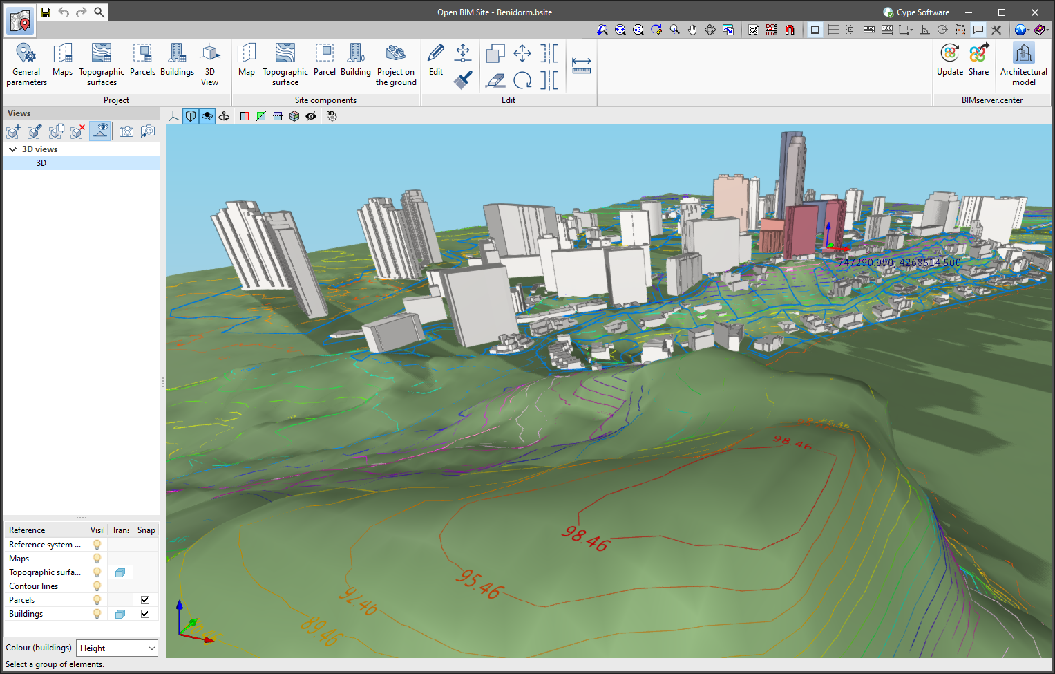
In the field of topography, contour lines are lines that connect points on a map with identical altitudes. Thanks to this technique, areas with different elevation differences can be easily identified.

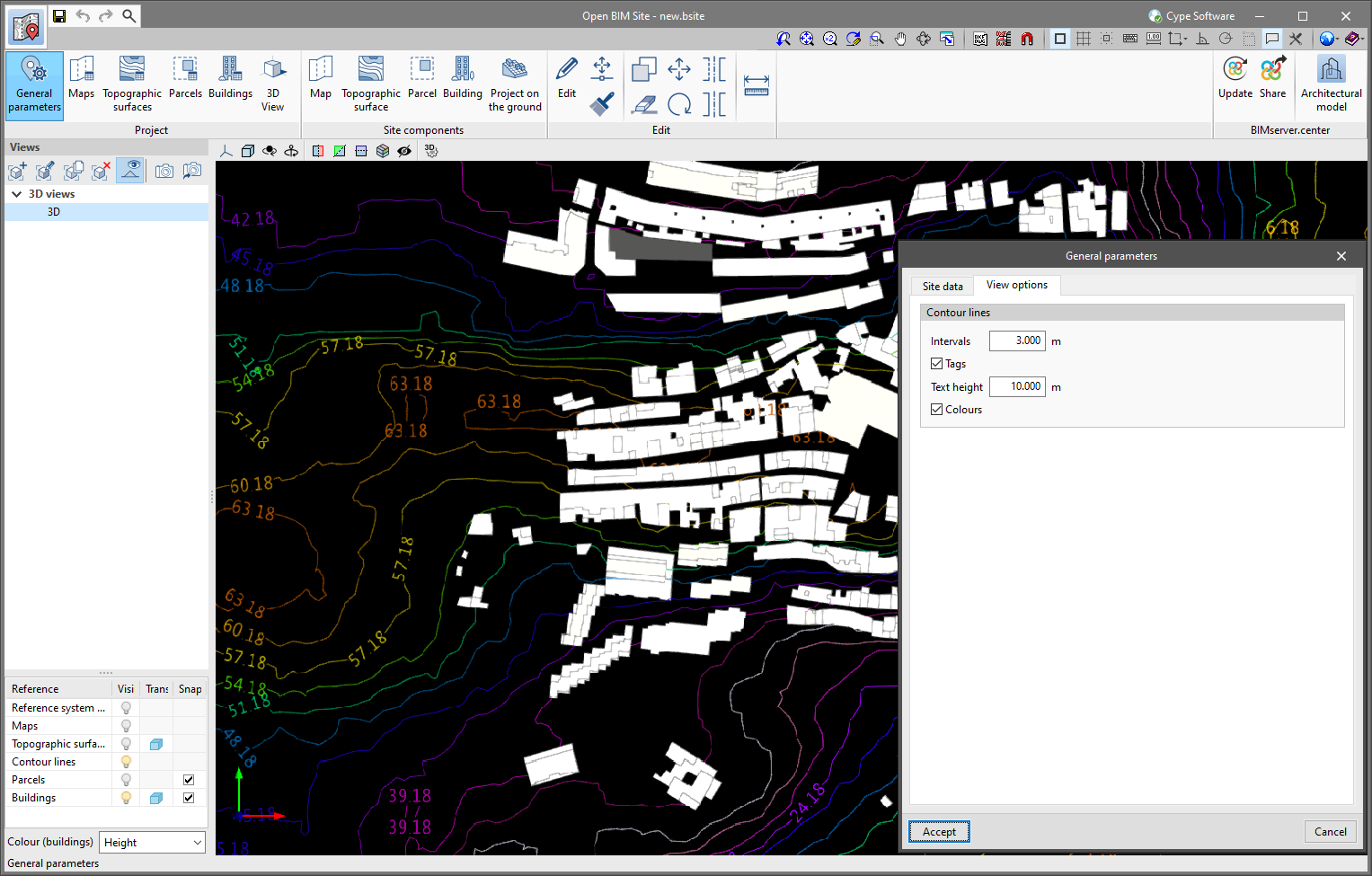
The generation of contour lines in Open BIM Site is automatic. However, users can control their visualisation of the 3D model of the site using the application's left-hand sidebar.

The "General parameters" panel, available in the application toolbar, has been divided into two tabs. The "Site data" tab contains the information related to the georeferencing of the model that was already present in previous versions of the tool. To configure the viewing of contour lines, the "View options" tab has been added with the following parameters:

  • Intervals
    Shows the vertical distance between two contour lines.

  • Tags
    When activating this option, a text is displayed along with the contour lines to show their elevation.
    • Text height
      Determines the tags’ text size.

  • Colours
    When this option is activated, a colour scale will be used to represent contour lines according to their elevation. Otherwise, the contour lines will be drawn in black.

The example job "Healthcare center" has been added.