Now, from the BIMserver.center project information window (displayed by clicking on the project name visible in the top right bar of the application), the owner's public profile page can be accessed on the BIMserver.center platform via the link inserted in the text representing the owner's name.

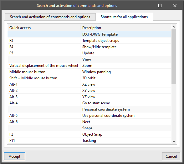
CYPE apps have keyboard shortcuts common to all programs. In versions before 2024.e, each program displayed the keyboard shortcuts for each app via the "Search and activation of commands and options" in the top left-hand corner of the programs.
As of version 2024.e, the "Shortcuts for all applications" tab has been implemented in the dialogue box displayed when selecting this option and it shows all the keyboard shortcuts common to CYPE apps.
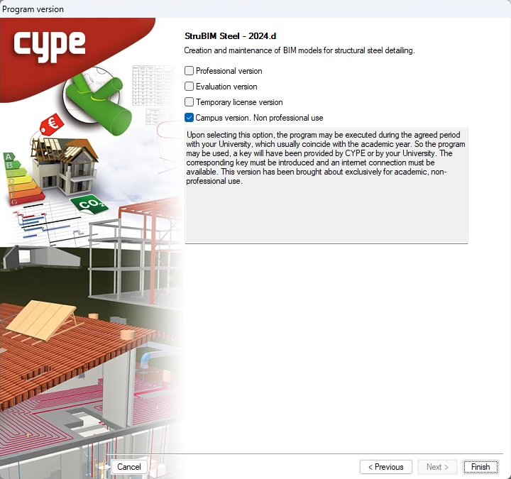
All CYPE programs can be installed in their different versions (Professional Version, Evaluation Version, Campus Version, Temporary License). In previous versions, users could only choose the type of version to be installed from the classic CYPE menu.
As of version 2024.a, the selection of version types has been implemented in all CYPE programs on the BIMserver.center platform.
As of version 2024.d, this selection can be made during the installation of all CYPE programs, regardless of where they are downloaded.
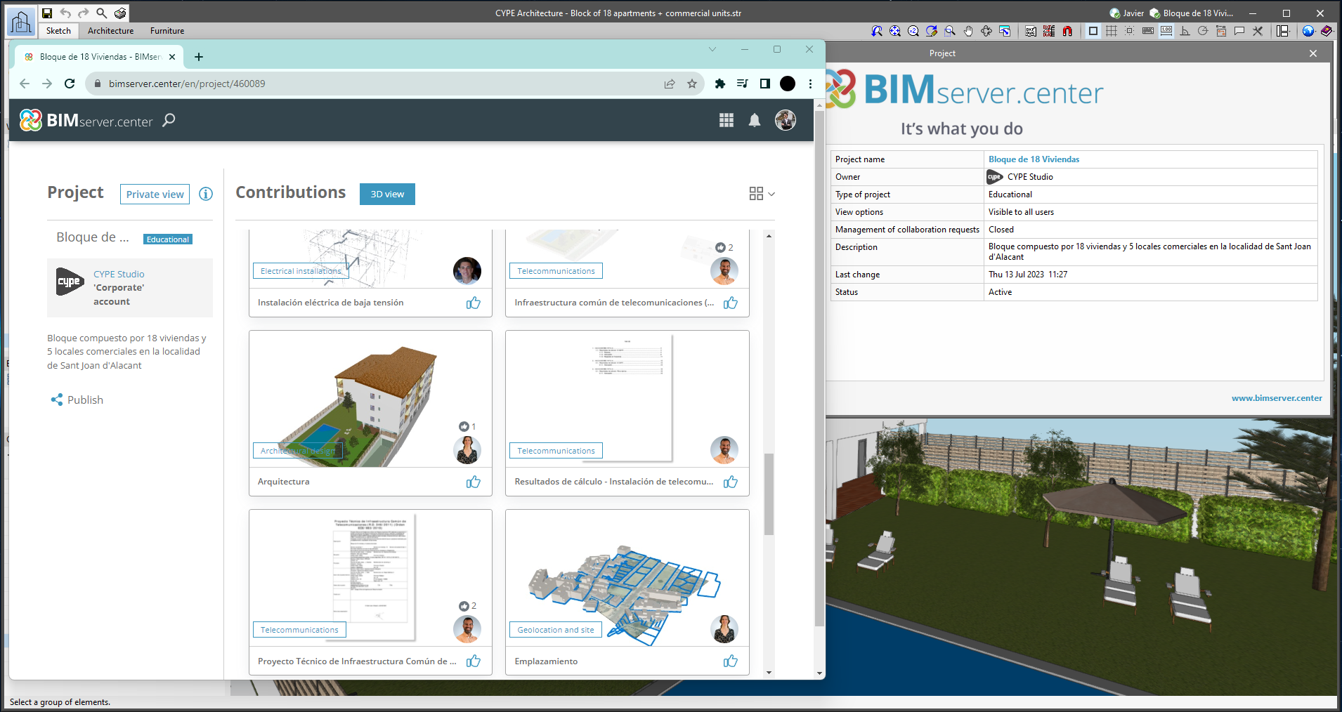
From the BIMserver.center project information window (displayed by clicking on the project name shown in the project information bar - upper right part of the application window) you can access the project page of the BIMserver.center platform via a link that has been inserted in the text indicating the project name.
Likewise, from the information window about the project contributions ("Contributions" option in the project information window), users can access the page of each contribution in the BIMserver.center platform. These links are inserted in the texts indicating the name of each contribution.
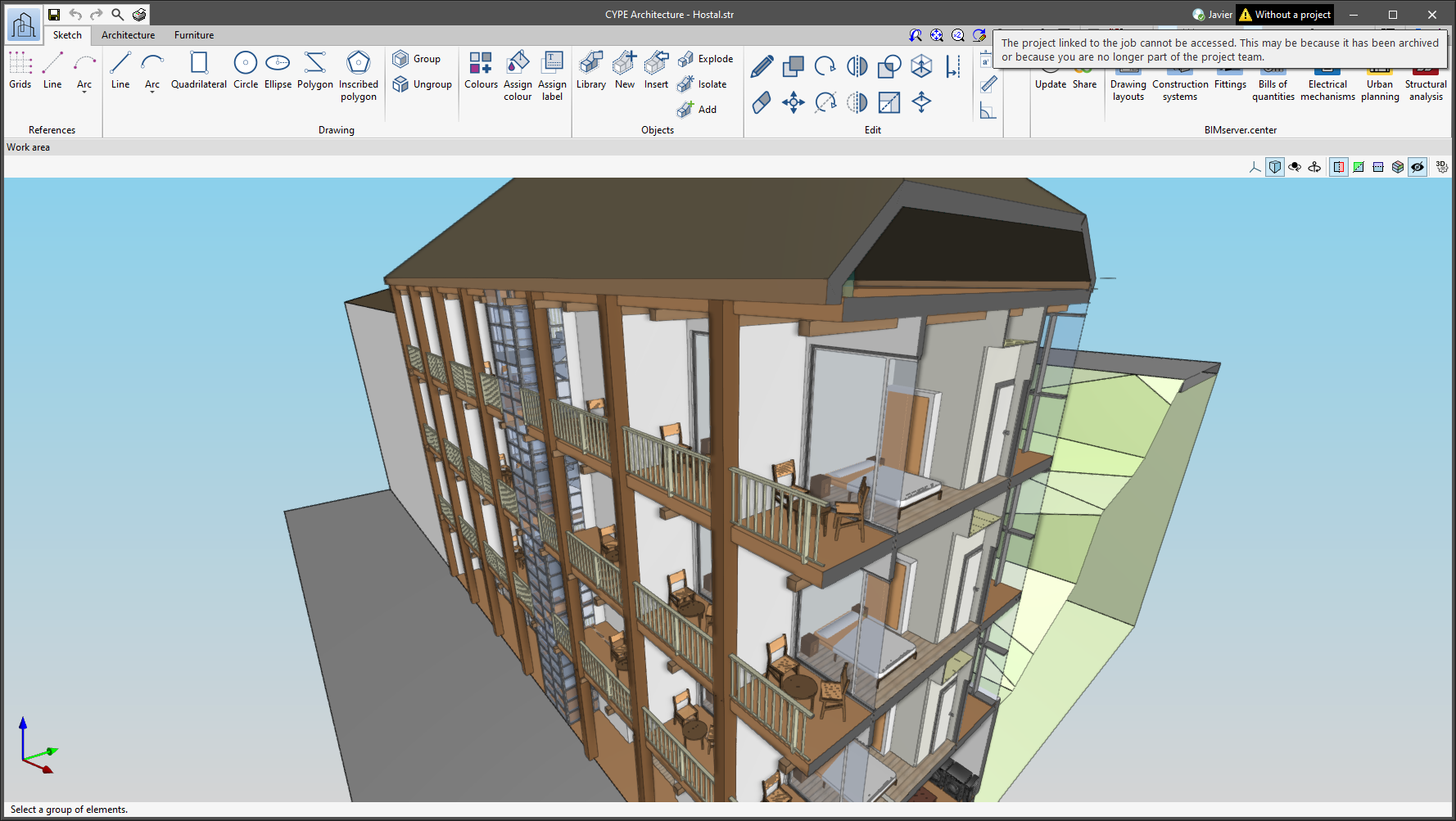
The status information bar of the BIMserver.center project is located at the top right of the window of the programs included in the Open BIM workflow. This bar has been available in the applications since version 2022.e and shows a warning icon when there is a problem with the connection to the project, as well as other things. Now, in version 2024.b, users can obtain more information about the warning by hovering the mouse cursor over the icon.
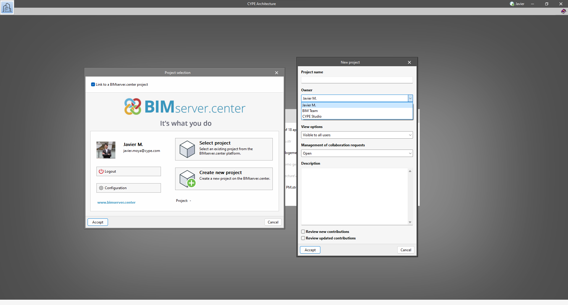
As of version 2024.b, users can create projects associated with a "BIMserver.center Corporate" account from all CYPE applications included in the Open BIM workflow. To do this, the "Owner" field has been added to the window for creating a new project. This is a drop-down menu that includes, as one of the available options, the logged-in BIMserver.center user name along with the "BIMserver.center Corporate" accounts to which it has access. When selecting the user name as the owner, the project will be associated with this personal account, as was the case in previous versions. On the other hand, if a BIMserver.center Corporate account is selected, the project will be associated with that account.
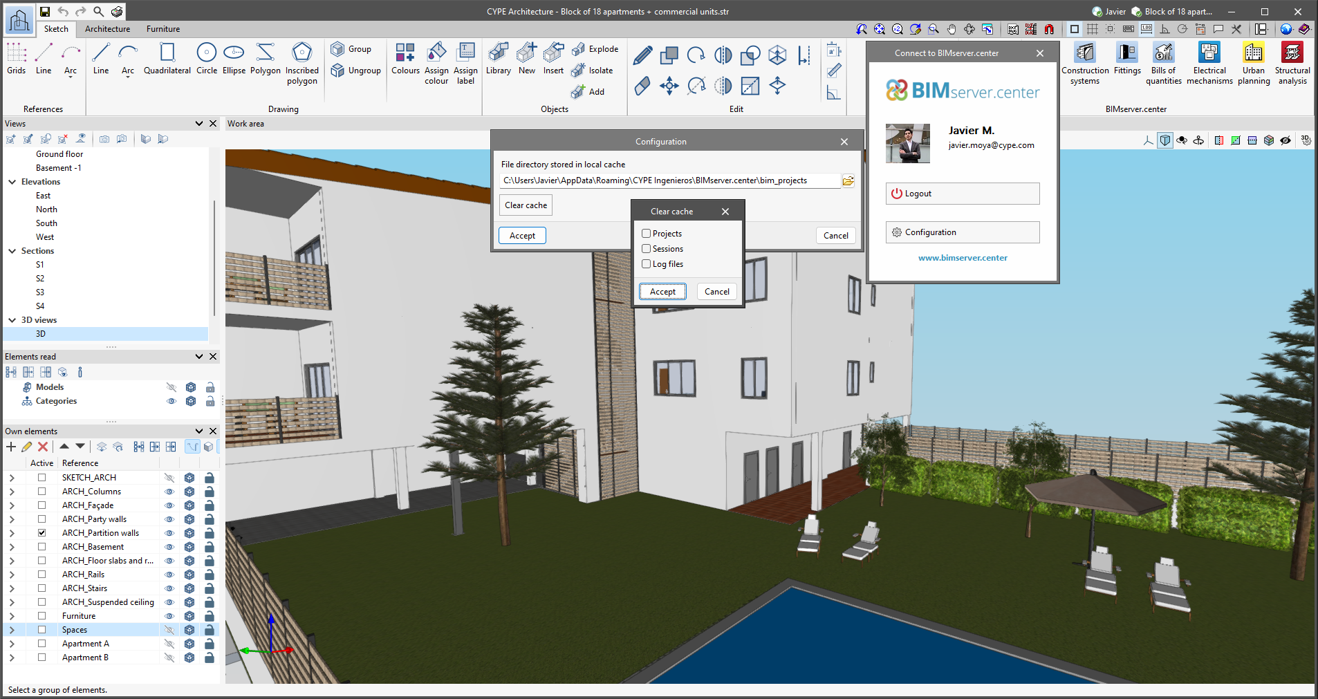
The "Clear cache" button has been added to the CYPE applications included in the Open BIM workflow in the "Configuration" dialogue box that opens with the following sequence of commands: Select any of the options in the "BIMserver.center" tool group > "Configuration" option in the dialogue box that appears. When clicking on "Clear cache", the following options are displayed:
- Projects
Deletes projects, contributions and documents downloaded from the platform that are in the "File directory stored in local cache". - Sessions
Deletes the data of any active sessions. This action will require applications to be re-authorised to access BIMserver.center. - Log files
Deletes transaction logging from applications with BIMserver.center.
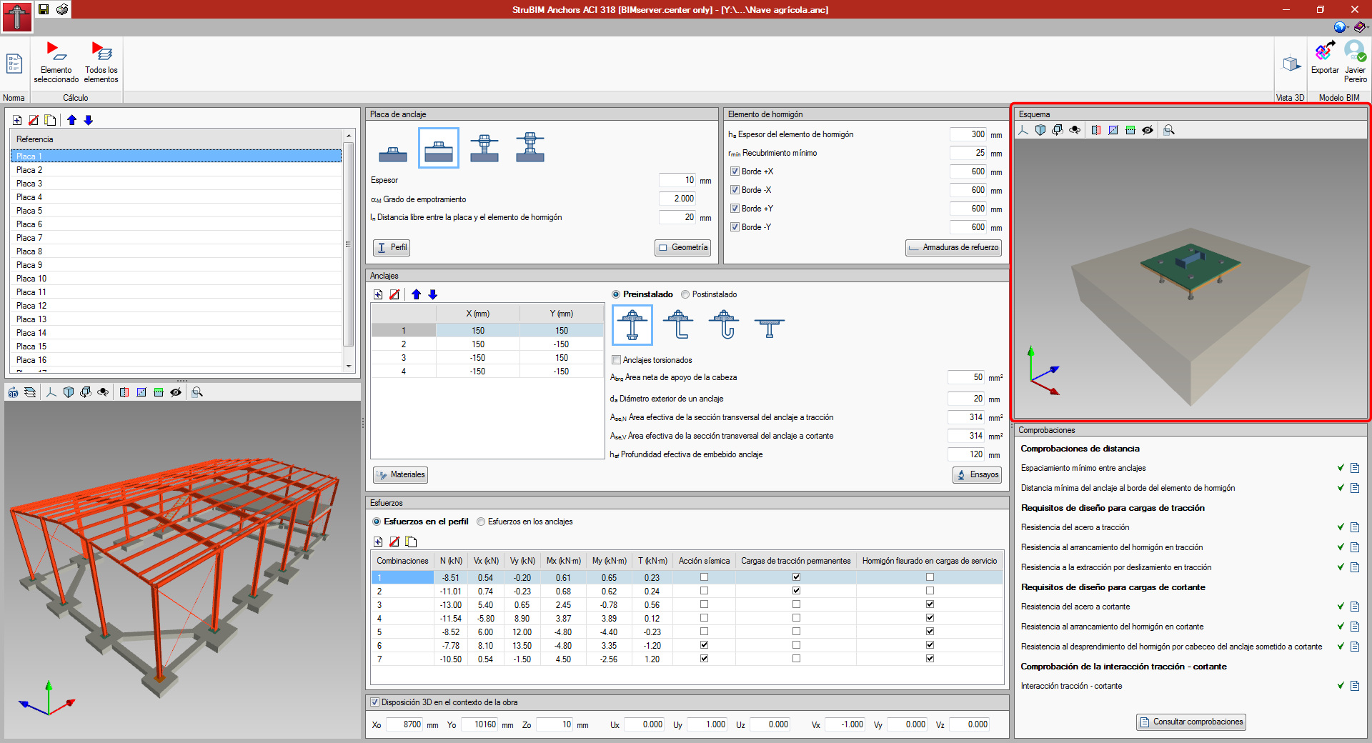
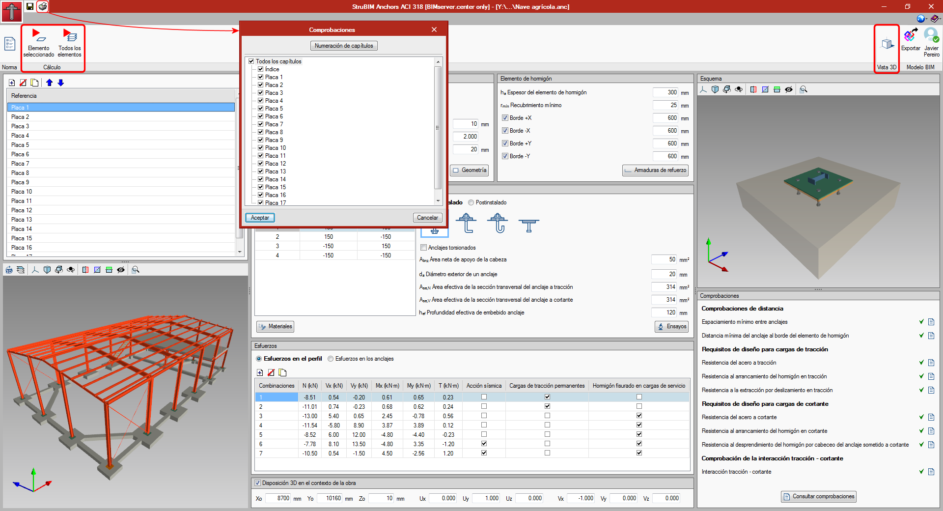
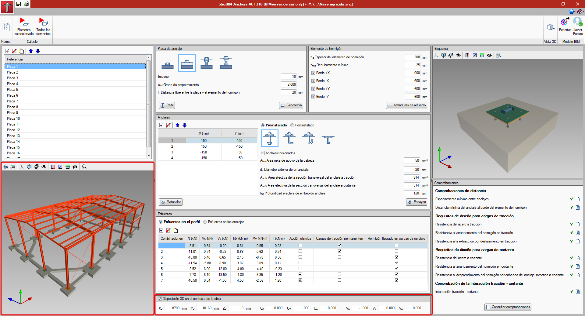
A button has been added in the upper left part of the interface where users can obtain a report where they can consult all the checks of the designed plates. In the dialog that appears, users can select the plates that are to appear in the results report.
The design button has been divided into two buttons, one to design the selected plate and another to design all the plates. This is because, when the number of plates and the number of combinations is high, it may take some time to design them all.
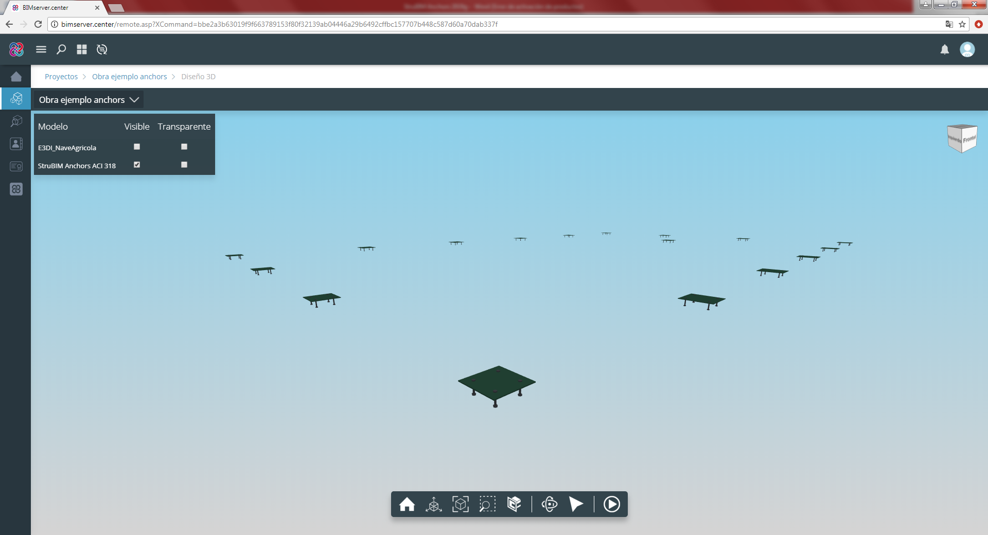
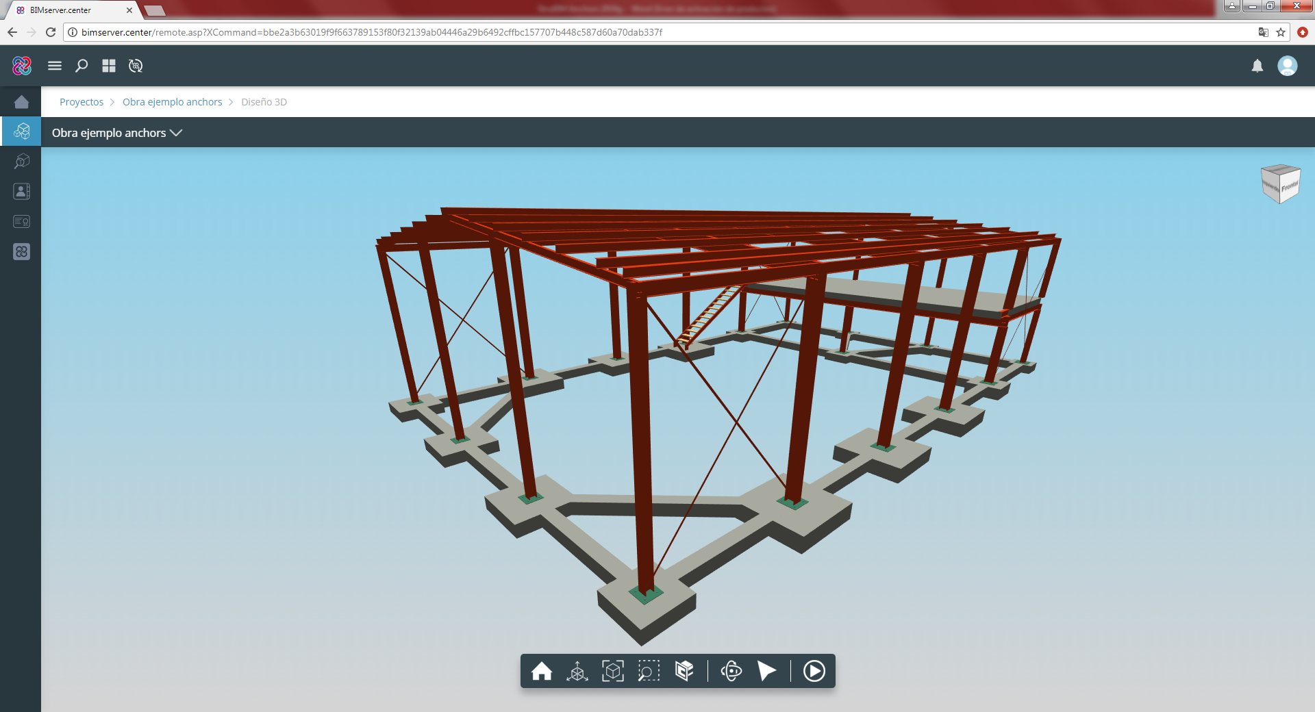
A button has been added in the top right to be able to see the 3D view of the BIM model in a new pop-up window.
View plates and anchors in the BIM model
The plates and anchors that are generated in the program can be viewed in the BIM model view. The model view will regenerate and display the latest changes of the plates and anchors by pressing the "Redraw" button ![]() located in the view panel itself. Furthermore, a new panel has been added in the lower part of the user interface to edit the position of the plate - anchors set in the context of the project.
located in the view panel itself. Furthermore, a new panel has been added in the lower part of the user interface to edit the position of the plate - anchors set in the context of the project.
Export to the BIM model
As of version 2019.g, the 3D view of the plate and anchors is exported to the BIM project via a GLTF file contained in the IFC file that is generated by the program. This IFC file will also contain the PDF file with the check reports, as was done in previous versions.
A 3D view has been added in the top right of the program interface. This view shows the section, plate, anchors, and concrete element. The properties of the 3D view are:
- The view adapts to the geometry that is introduced of all the elements.
- Regarding the anchors, the anchor that is selected in the input table for the anchor coordinates is highlighted.
- The reinforcement in the concrete element can be viewed depending on whether it has been introduced or not. The position of the reinforcement depends on the cover.