
Introduction
CYPETEL Wireless is a program created to perform indoor signal coverage studies of wireless telecommunications systems, such as Wi-Fi, Bluetooth and Zigbee networks.
To get started, a geometric model in IFC format is imported from a BIM project hosted on the BIMserver.center platform. The program can be used to configure the working frequencies, define the attenuation of signals in the building elements, establish the height of the working drawing in the spaces, and position transmitters and receivers.
After the analysis, the program displays the results in the form of contour plot and contour line diagrams overlaid on the floor plans and in the 3D view. It also offers tools to consult results, print reports and drawings, generate bills of quantities, and share project information through BIMserver.center.
Workflows supported by the program
As CYPETEL Wireless is an Open BIM tool and is connected to the BIMserver.center platform, it offers a range of workflow options.
Data entry
Importing BIM models
By linking CYPETEL Wireless to a BIM project on the BIMserver.center platform, you can perform the following actions:
- Importing the model containing the building’s geometry. This allows you to generate the building’s floor plans and import the rooms based on those extracted from the BIM model. The available options include the following:
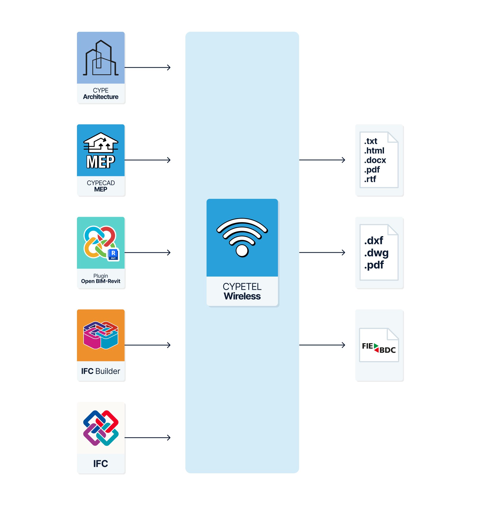
- Importing models designed in CYPE Architecture.
- Importing models designed in Autodesk Revit using the Open BIM - Revit plugin.
- Importing models designed in IFC Builder.
- Importing models in IFC format (generated by CAD/BIM software such as Allplan, ArchiCAD, and others) into the BIMserver.center project via the web platform.
Data output
- Exporting reports to HTML, DOCX, PDF, RTF and TXT formats.
- Exporting drawings to DXF, DWG and PDF formats.
- Exporting the bill of quantities to FIEBDC-3 format.
- Exporting data generated using CYPETEL Wireless to the BIMserver.center platform in IFC and GLTF formats. This enables authorised project stakeholders to view the data.
Work environment
The program has a simple work environment, divided into two tabs: "Floor plans" and "Bill of quantities"
"Floor plans" tab
The default tab activated at start-up is the "Floor plans" tab. It displays:
- At the top are all the tools needed to complete the project, divided into groups for the configuration, the library of building elements, the definition and entry of emitters and receivers, editing and the analysis.
- On the left-hand side, the floor plans of the model, the tree of building elements and the 3D model are displayed.
- In the central right-hand part of the start screen is the modelling area, which is used to enter, edit and display all project elements in 2D.
"Bill of quantities" tab
On the other hand, the "Bill of quantities" tab also shows:
- A top toolbar containing the tools for creating and editing the bill of quantities, as well as the management and report creation tools.
- A specific area for structuring the bill of quantities, in the central part.

General tools in the CYPETEL Wireless interface
CYPETEL Wireless includes tools that are common to other CYPE programs and are available in the following areas of the interface:
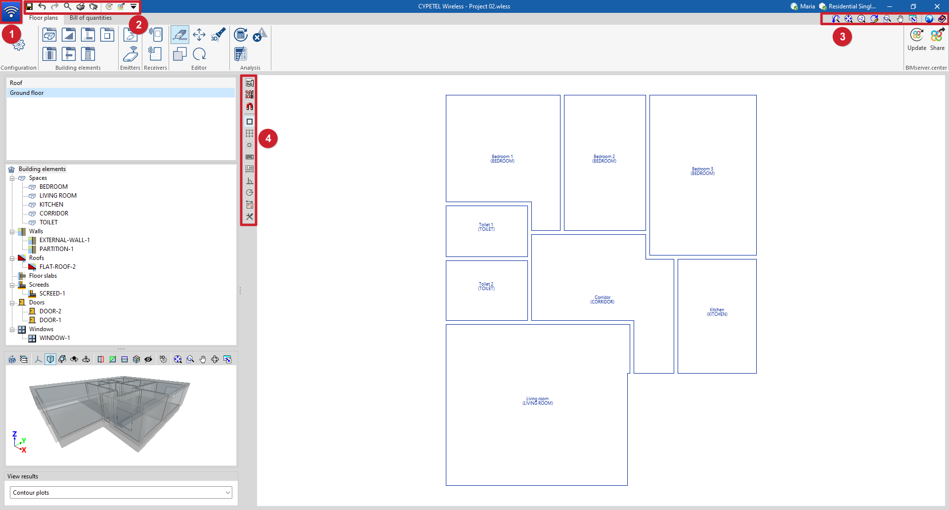
- "File" menu (1)
Create, open or save projects, access the file manager, and view lists and plans.
- Tools in the top-left corner (2)
Save the file, undo and redo changes, and generate reports and drawings, as well as search for and quickly access other program utilities. You can also import and export data to BIMserver.center.
- Tools in the top-right corner (3)
Change the drawing views, access general settings and open the "Help" menu.
- Left-hand side panel (4)
Manage templates and their screenshots, enable various tools to assist with inserting elements, and configure the appearance of the various graphical elements displayed on screen.
Data input and output sequence for the design of a wireless network
Wireless network installations can be defined and analysed in the program using the following sequence of data input and output:
- Creating a new project (from "File", "New").
- Connecting to BIMserver.center, selecting and importing floor plans and room types extracted from the BIM model, and initial configuration (defining operating frequencies and analysis options).
- (Optional) Checking the initial settings (under "Settings"), including reviewing the operating frequencies and analysis options.
- Reviewing structural elements (from the "Structural elements" menu or the structural elements tree), including spaces (defining the height of the working plane in each one) and the structural properties of each element (editing, if necessary, the attenuation proposed by the program).
- Defining the types of emitter to be included in the project (under "Emitters", "Emitter types"), including their properties (operating frequencies, power and radiation pattern).
- Placing the transmitters in the areas shown on each floor within the workspace (under "Transmitters", "Transmitter"), modifying their properties and 3D layout if necessary.
- Installing the receivers in the locations shown on each floor within the work area. This can be done in two ways:
- Manually (from "Receivers", "Transmitter").
- Automatically, using the wizard (under "Receivers", "Automatic allocation of reception points").
- Analysing the installation, viewing the results on screen (in the form of contour plots or contour lines) and in the results reports (via "Analysis").
- Obtaining reports and drawings (from "File", "Reports/Drawings").
- (Optional) Generating a bill of quantities (the "Bill of quantities" tab, under "Reports", "Bill of quantities reports").
- Exporting to BIMserver.center (from "BIMserver.center", "Share").
Creating a new job, linking to a project and importing data
When you launch the program and click on "New", you are given the option to create a "New job", which can then be integrated into an existing project on BIMserver.center.
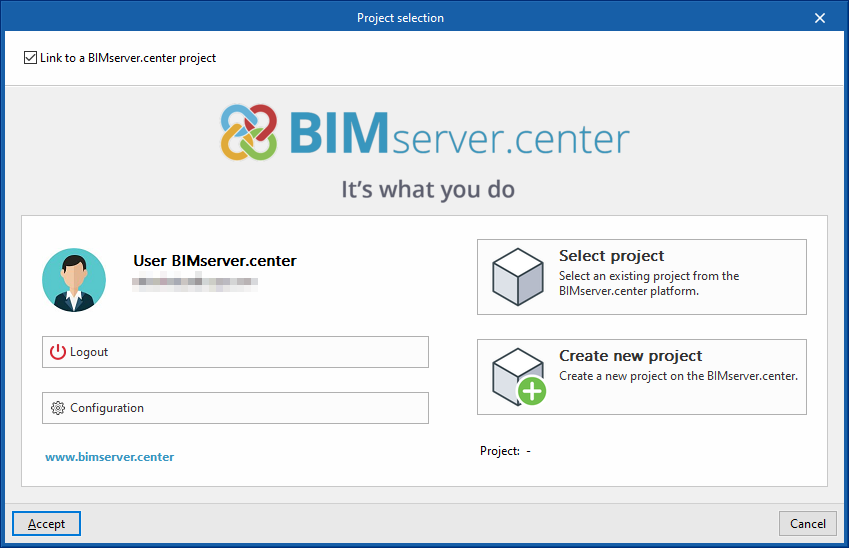
This is done in the "Project selection" window, which offers the following options:
- On the left-hand side, you can sign in using a BIMserver.center account.
- On the right, use the "Select project" option to choose an existing project. You also have the option to "Create a new project". In that case, the project you create will be visible on BIMserver.center from that point onwards.
- The box labelled "Link to a BIMserver.center project", located in the top-left corner, must be ticked. If it is not, the program will display a message stating that the BIM model does not contain the information required to continue.
Once the new project has been created, you will be taken to the program’s main interface after completing the import wizard. At any point thereafter, whilst working on the project, you can share or import project files via the “BIMserver.center” panel, located in the top-right-hand corner of the main interface.
Importing BIM models
When creating a new project, if you have selected a project hosted on the BIMserver.center platform via "Select project", the "Import BIM models" window will appear, displaying the files contained in that project in IFC format.
The app allows you to include one or more existing models from that project. To do this, tick the "Import" box and confirm. You must decide whether the "Type" of each file is "Initial" or "Additional".
The program’s 3D view will then display the imported models, including both the starter files and the additional files. Furthermore, the program allows you to import the geometry of floor plans and spaces from the file marked as the starter file using a configuration wizard.

Setup wizard: selecting floor plans, space types to be imported, and initial configuration
From the "Import BIM Models" window, the program opens the "Configuration" wizard, which consists of the following steps:
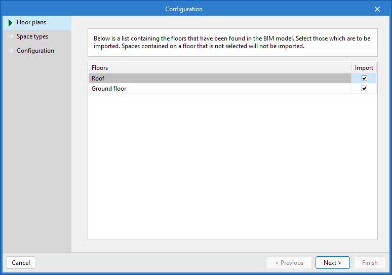
- In the first step, a list of the floors found in the BIM model is displayed. Here, you can select the floor plans to be imported.
| Note: |
|---|
| Spaces included in an unselected floor will not be imported. |
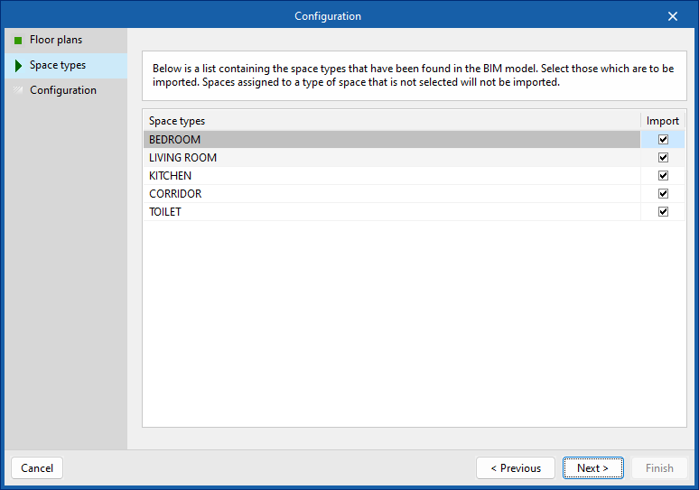
- The next step displays a list of the room types found in the BIM model. Here, you can select the space types to import.
| Note: |
|---|
| Spaces assigned to an unselected space type will not be imported. |
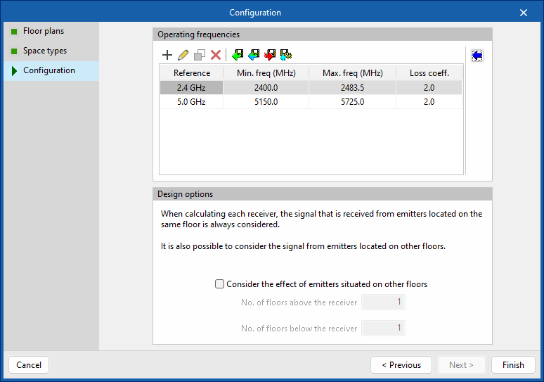
- In the next step, you must define the operating frequencies and analysis options.
- By clicking the blue arrow, you can automatically import the frequency bands based on the selected network type. The program includes the "WLAN/Wi-Fi" standard, as well as the "WPAN/Bluetooth" and "LR-WPAN/Zigbee" options. You must also specify the regulatory body, as this determines the limits of the available frequency bands:
- "FCC" (Federal Communications Commission) applies to the Americas, Australia, New Zealand and various parts of Asia and Oceania.
- "ETSI" (European Telecommunications Standards Institute) applies to Europe, the Middle East, Africa and parts of Asia and Oceania.
- Finally, you can choose to include signals from transmitters located on other floors when analysing the signal for each receiver. In this case, you would need to specify the number of floors above and below the receiver.
- By clicking the blue arrow, you can automatically import the frequency bands based on the selected network type. The program includes the "WLAN/Wi-Fi" standard, as well as the "WPAN/Bluetooth" and "LR-WPAN/Zigbee" options. You must also specify the regulatory body, as this determines the limits of the available frequency bands:
| Note: |
|---|
| It should be noted that the frequency bands may not be exact, given the variations set by the authorities in each country. |
| More information: |
|---|
| The operating frequencies and calculation options can be changed later via the "Settings" option in the main toolbar. |
Import results
Finally, in the last step, the "Import results" table is displayed, showing information about the BIM model elements that have been processed, created, modified or deleted.

Checking the initial settings
In the "Floor plans" tab, within the "Configuration" section of the main toolbar, you will find the "Configuration" option, which allows you to review the working frequencies and analysis options defined when importing the BIM model:

Configuration
From this dialogue box, you can configure:
- Operating frequencies
- Frequencies can be created and edited using the first set of options at the top of the table or via the wizard accessed via the blue arrow.
- Assistant for importing operating frequencies
Allows you to select:- Type of network ("WLAN/Wi-Fi", "WPAN/Bluetooth" or "LR-WPAN/Zigbee")
- Regulatory committee ("FCC" or "ETSI")
- Assistant for importing operating frequencies
- The second set of options in the top toolbar allows you to import and export items to files on your hard drive.
- Frequencies can be created and edited using the first set of options at the top of the table or via the wizard accessed via the blue arrow.
- Design options
Select the "Consider the effect of emitters located on other floors" option and define:- Number of floors above the receiver
- Number of floors below the receiver


Reviewing building elements
In the "Floor plans" tab, within the "Building elements" section of the main toolbar, you will find the options that allow you to review the areas and construction properties of each element:

Spaces
The existing spaces in the project must be checked and the height of the work surface must be defined for each one.
This can be done via "Spaces" in the "Building elements" section, or via the building elements tree located in the left-hand column of the interface. Using the latter method, it is possible to view the highlighted spaces in the 3D view.
- Edit ("Spaces")
Change the default height of the work surface.
| Note: |
|---|
| Once the spaces have been checked, the orange warning markers will be removed from the tree, and in the "Areas" dialogue box, green tick marks will appear in the "Checked" column. |


Building elements
The program includes a library for each type of building element:
- Roofs
- Floor slabs
- Windows
- Walls
- Floor slabs
- Doors
The construction properties of each imported element must be checked, and the attenuation proposed by the program must be edited, if necessary, for each frequency band.
This check can be carried out using the options in the "Building elements" group library or via the building elements tree located in the left-hand column of the interface. Using the latter method, it is possible to view the highlighted building elements in the 3D view.
- Edit("Structural element")
- The first set of options in the top toolbar allows you to import and export elements to files on your hard drive.
- The blue arrow opens the "Building element selection" wizard, which allows you to retrieve the attenuation values built into the program, based on the selected structural element.
- From the table, you can change the default attenuation value for each operating frequency.
| Note: |
|---|
| Once the structural elements have been checked, the orange warning markers will be removed from the tree, and in the dialogue box for each element, green check marks will appear in the "Checked" column. |


Inserting emitters
In the "Floor plans" tab, under the "Emitters" section of the main toolbar, you will find the options for creating and adding emitters:

Types of emitters
This allows you to specify the wireless access points you wish to include in the project.
In the first dialogue box, "Types of emitter", you need to add a new element to the list using the first set of options in the top toolbar. The second set of tools allows you to import and export elements to files on your hard drive.
In the second dialogue box, "Transmitter type", the program requires the following parameters to be defined:
- Reference
Emitter's reference number. - Properties
Adds transmitter properties, defining the gain and radiation pattern of the transmitter antenna for each frequency band. To add an element to the properties table, you must define:- Operating frequencies
Selects the frequency band from those defined above. - Minimum power
Sets the minimum power (dBm) for the selected frequency band. - Maximum power
Sets the maximum power (dBm) for the selected frequency band. - Radiation diagram
Edits the following properties:- Gain
Sets the antenna gain for the transmitters. - Predefined antenna types
A wizard that allows you to import the properties of various antenna types included in the program. From within the wizard itself, you can view a preview of the "Azimuth/Elevation" and "3D view". - Azimuth / Elevation
Displays the azimuth and elevation angles of the transmitter antennas. - 3D view
Displays the radiation pattern of the transmitter antennas in three dimensions. - Configure
Sets the azimuth and elevation angles of the transmitter antennas. This enables the user to set the direction of the radiation pattern according to the requirements of the installation.
- Gain
- Operating frequencies


Emitter
Adds pre-defined emitters to the workspace by selecting a point on the floor plan. Once they have been added to the installation, their spatial position is also visible in the 3D view.
To insert an emitter type, the program requires the following parameters to be defined:
- Reference
Emitter's reference number. - Properties
Edits the emitter's properties:- Type
Selects the emitter type. The defined types can be created and edited using the option to the right of the drop-down menu. - For each defined operating frequency, the following must be set:
- Power
Sets the power within the range specified when creating the emitter type. - Azimuth
Sets the azimuth angle of the emitter antennas. - Elevation
Sets the elevation of the emitter antennas. - Azimuth / Elevation
Displays the azimuth and elevation angles of the emitter antennas. - 3D view
This feature allows you to view the radiation pattern of the emitter antennas in three dimensions.
- Power
- Type
- 3D layout
- Height
Defines the elevation of the emitter on the floor plan.
- Height


Inserting receivers
The options for creating and adding receivers can be found in the "Floor plans" tab, within the "Receivers" section of the main toolbar:

Receivers
Defines the receivers and inserts them manually into the workspace by selecting a point on the floor plan. The spatial arrangement of the receiver points is determined at the user’s discretion.
The program requires the following parameters to be defined:
- Reference
Recipient's reference number. - Transmitters
Selects a emitter from those previously created, and specify:- Distance to the emitter
Sets and locks the distance between the receiver and the transmitter. If it is not locked, the program will automatically calculate and assign the distance. - Structural elements
Creates or edits structural elements by selecting the element type (wall, roof, floor slab, floor, door or window), the specific type and the quantity. You can lock this section to prevent the program from modifying it during the analysis. Alternatively, you can leave it blank so that the program assigns it automatically during the analysis. - Results
Displays the following results for each operating frequency:- Frequency band [MHz]
- Power of the signal of the emitter [dBm]
- Gain of the emitter antenna [dBi]
- Signal propagation due to distance [dB]
- Signal propagation losses via floors [dB]
- Signal propagation via walls [dB]
- Total signal propagation loss [dB]
- Signal power in the receiver [dBm]
- Distance to the emitter


Automatic distribution of reception points
Inserts receivers automatically into the workspace using the "Automatic distribution of reception points" wizard.
In the wizard, you can deselect the areas where you do not want to place the receivers.
| Best practice: |
|---|
| To reinsert the reception points and replace the existing ones, you must first use the "Delete" tool in the "Edit" menu. |


Editing tools
The "Edit" section of the main toolbar contains the options for editing the model elements:

The following tools are available:
 | Delete | Deletes a previously entered item. |
 | Move a group | Moves a group of items. |
 | Lighting 3D | Highlights a selected element or group of elements in the 3D view in orange so that they are easily identifiable. |
 | Copy | Creates a copy of one or more items. |
 | Rotate a group | Highlights a selected element or group of elements in the 3D view in orange, making them easily identifiable. |
Analysis and checks
The "Analysis" section of the main toolbar contains options for analysing and checking the model elements in accordance with the user-defined requirements:

Refresh results
Analyses the power balance for the installation in accordance with the latest changes and updates and modifies any unlocked calculated parameters.
After updating the results, the program displays warning messages regarding items that contain errors or fail a check; it also allows you to view the results on screen and access the check reports (using the "View results" option in the same section of the main toolbar).

View results
Displays the checks carried out during the most recent analysis performed in the job. Once you have selected this option, you can hover the cursor over an element to view its results on screen, or click on a reception point to go directly to the specific list of results for that point.
| Best practice: |
|---|
| If any changes have been made to the system components, you must use the "Update results" option so that the program can update the results displayed. |


If the results preview is disabled and you click on a reception point, a panel opens allowing you to view and edit the structural elements that the signal passes through, as well as the distance to the emitter. You can also view this distance in the 3D model, where the emitter is highlighted in orange to make it easier to locate.
| Note: |
|---|
| This results query is particularly useful, as it allows the transmitter to be repositioned in the event that the structural elements it passes through cause significant signal loss. |

Show/Hide results
Shows or hides the result display options (contour plots and contour lines) overlaid on the floor plans.

"Bill of quantities" tab

The "Bill of quantities" tab in CYPETEL Wireless contains tools designed for generating and managing measurements and quotations.
From this window, you can manage general settings, certificates, cost databases, mapping and project databases. It also offers options to import and export data in BC3, manually edit the bill of quantities, manage its display, generate reports and update quantities, amongst other functions.
| Further information: |
|---|
| The following link provides detailed information on the "Bill of quantities" tab in Open BIM apps that include it, explaining all the available features in greater detail. |

Results output
The analysis results can be obtained in the following ways:
Viewing results on screen
After the analysis, the results can be displayed directly on the screen by means of contour plots or contour lines, both on the floor drawings and in the 3D view. The program indicates the highest and lowest power zones depending on the proximity to the emitter or wireless access point. From "View results" at the bottom left of the interface, the display option between contour plots or contour lines can be changed.
| Best practice: |
|---|
| To regenerate the 3D view, click on the "Redraw" option located on the top toolbar of the 3D model. |


On the other hand, when selecting the "Consult results" option in the "Analysis" group, CYPETEL Wireless shows the results in the tooltip or informative text that appears when the cursor is positioned on an element in the system, such as the reception points or transmitters, as well as the checks carried out on them.
Results reports by element
Using the "Consult results" option in the "Analysis" group and clicking on the reception points, the corresponding report of results for each element can be accessed.
These reports show a summary of the analysis results of the selected element and detail the calculation expressions used, as well as the magnitudes obtained.
Job reports
The program can print the reports directly or generate HTML, PDF, TXT, RTF or DOCX files.
The reports are obtained via the "Reports" option in the "File" menu or in the top toolbar.
- Report
Displays information on the analysed results for the system entered, organised in the following sections:- Floor plans
For each floor, a table with the minimum and maximum received power (dB) for each type of space is displayed, as well as a drawing for displaying the results by means of contour plots. - Emitters
Displays a table showing the power (dB) to which each emitter is set, indicating its reference and location.
- Floor plans

Drawings in DWG, DXF or PDF format
The program can print the drawings of the job on any graphic peripheral configured on the computer, or create DWG, DXF or PDF files.
Editing the drawing allows the following options to be configured:
- Scale
- Reference
- Floor plans
- Details
The drawings can be obtained via the "Drawings" option in the "File" menu at the top of the interface.


GLTF file compatible with BIMserver.center
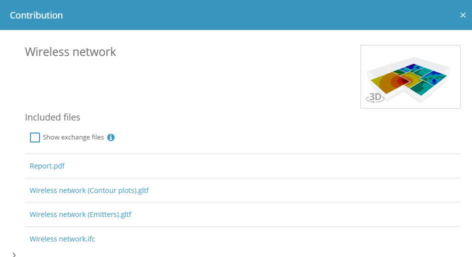
When exporting a job that has been analysed from CYPETEL Wireless to the project hosted on the "BIMserver.center" platform, the IFC file generated includes two .gltf files: one with the coverage contour plot diagrams in the 3D view and the other with the position of the emitters. This means that both can be visualised independently in:
- on the online platform;
- in the BIMserver.center app for iOS and Android;
- in virtual reality and augmented reality;
- in other CYPE programs.
The .gltf file corresponding to the emitters provides detailed information on the emitters, such as:
- Emitter reference.
- Emitter type.
- Installation height.
- Transmitting power.
Bill of quantities
In addition to generating "Bill of quantities reports", the system's bill of quantities can be exported to the standard FIEBDC-3 (.bc3) format so that it can be read by any compatible application.
To carry out the export, simply use the "Export BC3" tool in the "Import/Export" group of the "Bill of quantities" tab, assign a name to the file and activate the desired boxes to include associated information (graphic information, attached documents, specifications, technical information, etc.).
Integration into the BIMserver.center platform
Many of CYPE's programs are connected to the BIMserver.center platform and allow collaborative work to be carried out via the exchange of files in formats based on open standards.
Please note that, to work on BIMserver.center, users can register on the platform free of charge and create a profile.
When accessing a program connected to the platform, the program connects to a project in BIMserver.center. This way, the files of the projects that have been developed collaboratively in BIMserver.center are kept up to date.

| More information: |
|---|
| For further details related to using CYPE software via the BIMserver.center platform, please click on this link. |
Options available on CYPETEL Wireless
The "BIMserver.center" section of the main toolbar contains the features needed to use the program alongside other BIMserver.center tools:

Updating
Updates the information contained in the models previously imported into the project, or imports new models if required. Floors and spaces are imported using the file marked as "Initiator".

During the update process, just as when creating a new project, you can read and import floor plans and room types from the BIM model. This allows the program to automatically generate floor plans and/or spaces or update them based on the latest changes. It also allows you to reconfigure work frequencies and analysis options.
Sharing
Exports the installation data generated by the program to BIMserver.center so that you can share it with other users.
During the export process, you can specify the details relating to the IFC file to be exported:
- Name
- Description
- Additional files
- Reports
CYPETEL Wireless exports, alongside the IFC file, two files in GLTF format: one containing the positions of the transmitters and another containing the coverage contour plot diagrams in the 3D view. Furthermore, if the "Reports" checkbox has been ticked, a .pdf file is generated containing the results of the analysis.