Managing views, read elements and own elements
The various elements of the project can be viewed via the following panels located on the left-hand side of the program’s main interface, which are visible in both the "Building" and "Systems" tabs:
- Views
- Elements read
- Own elements
- View
Each of these is set out below:
View management
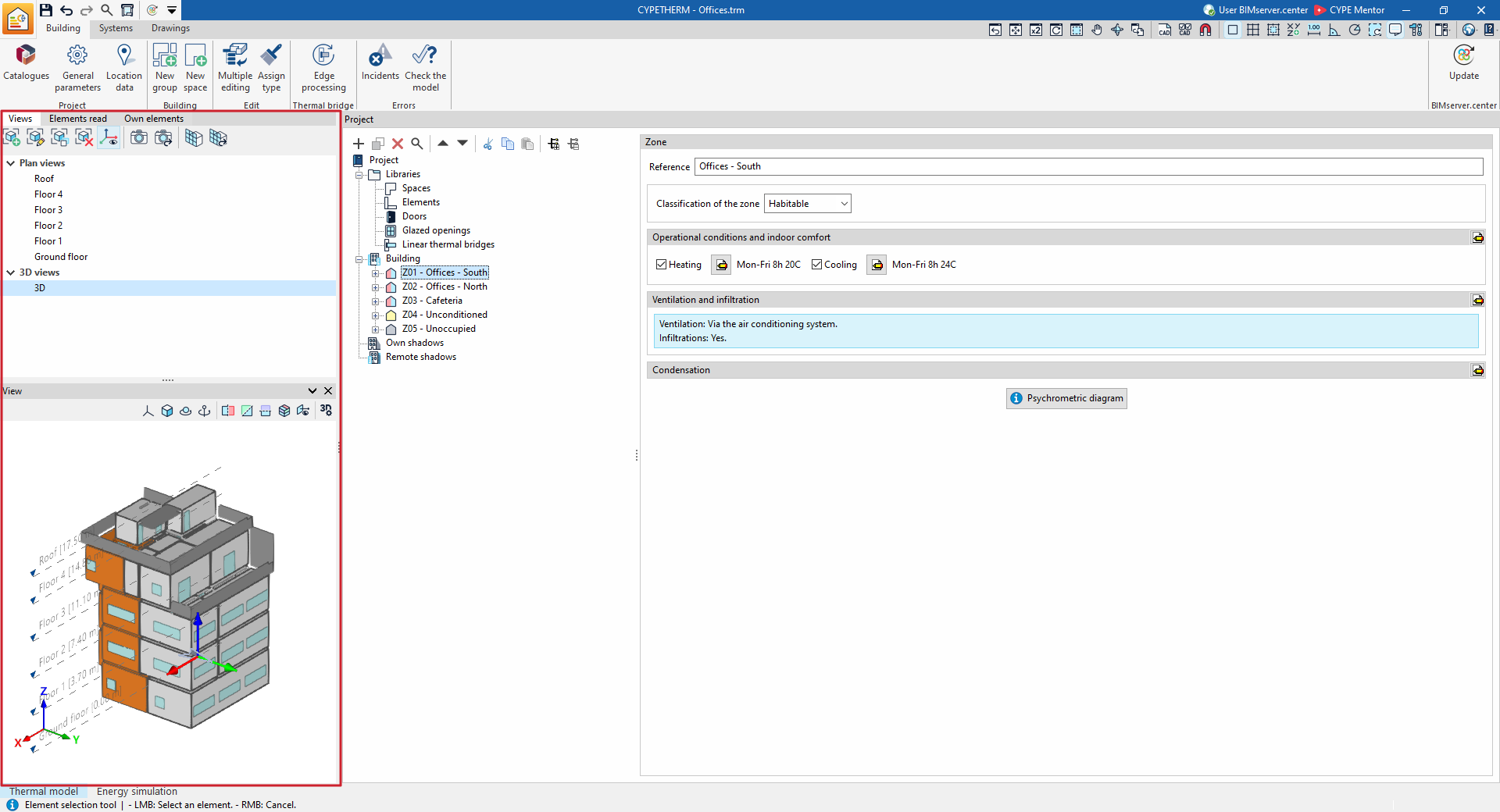
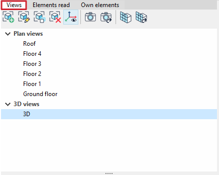
This panel, as in other CYPE programs, provides access to various "Views" to facilitate navigation and the model definition process, such as plan views or three-dimensional views.
Floor plans are generated automatically from the floor plans created in the "3D model" tab when using the "Geometric model" option. They are also generated automatically from the BIM model data if the "Import thermal model from the project" option has been selected when creating a new project.
In any case, you can use this panel to set up and create additional views if necessary.
| Further information: |
|---|
| The view management system is a feature common to several CYPE tools. You can find further information via the following link. |
The view selected in this panel will be displayed in the "View" window, which is located by default in the bottom left-hand corner of the interface.
Managing elements
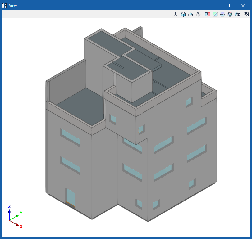
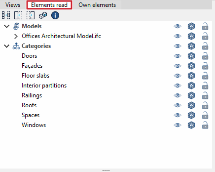
The "Read elements" panel lets you control the visibility (in the "View" panel) of the various models that make up an Open BIM project developed on the BIMserver.center platform and which have been imported into CYPETHERM (for example, the original architectural model). This way, the elements from these external models can be displayed for reference purposes.
There are two ways to manage the visibility of these models:
- In the "Models" drop-down menu, you can filter the various imported .ifc models and sub-models (such as ‘Architectural Model’ or ‘Spaces’).
- In the "Categories" drop-down menu, you can filter the categories of elements found in the imported models, following the IFC schema classification ("Roofs", "Façades", "Floor slabs", "Interior partitions", "Doors", "Spaces", "Windows", etc.).
On the right, the options for managing the visibility of read elements can be used to:
- Toggle the visibility of elements in the workspace (using the "Visible" option).
- Change the "Display mode" of the elements by choosing between normal view, transparent view or wireframe view.
- Lock the "Snap" fields so that they cannot be captured or selected during the various data editing processes.
From the top bar in this section, you can also:
- Using the "Isolate selection" option, you can left-click in the "View" to select a number of elements so that they remain visible; when you right-click, any elements that have not been selected will be hidden.
- From the "Hide" option, you can select a number of elements in the "View" using the left mouse button so that, when you click the right mouse button, they are hidden.
- Selecting "Show all" reverses the actions mentioned above.
- From the "Appearance" menu, you can switch the display between "Normal drawing" and "Monochrome drawing".
- Finally, using "BIM Information", you can click on an element to open a window displaying its parameters and values.
Managing own elements
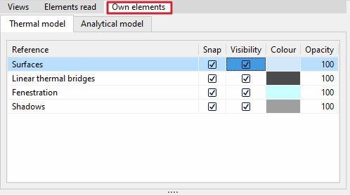
The "Own elements" panel allows you to control the visibility and/or snap (in the ‘View’ panel) of the own elements that make up the CYPETHERM model.
Two tabs are displayed:
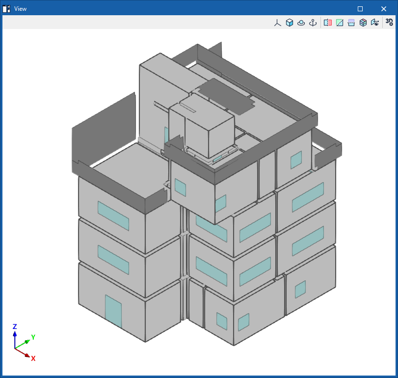
- In the "Thermal model" tab, for each of the following categories, you can enable "Snap", set its "Visibility", and change its "Colour" and "Opacity":
- Surfaces
- Linear thermal bridges
- Gaps
- Shadows
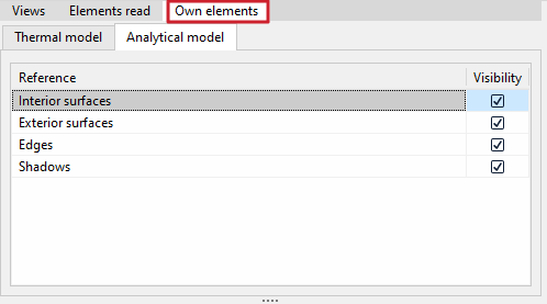
- On the "Analytical model" tab, you can enable "Visibility" for each of the following categories:
- Interior surfaces
- Exterior surfaces
- Edges
- Shadows
| Note: |
|---|
| The thermal model contains information on the building’s thermal behaviour (including the thermal properties of the building elements or the thermal characteristics of the spaces). The analytical model contains information from the analysis of solids and surfaces that is required for the calculation (such as the junctions between surfaces, or the relationships between edges and the elements that comprise them). These models are generated by using the "Geometric model" option in the "3D model" tab, or by selecting the "Import thermal model from the project" option when creating a new project. To import the model from the BIMserver.center project, you must use a program capable of generating analytical models, such as IFC Builder or Open BIM Analytical Model. |
View
The "View" panel, at the bottom left of the interface, displays the "Read-in elements from external models and/or the "Own elements" of the CYPETHERM model, depending on the settings specified in the relevant panels, and depending on the 2D or 3D view selected in the "Views" panel.
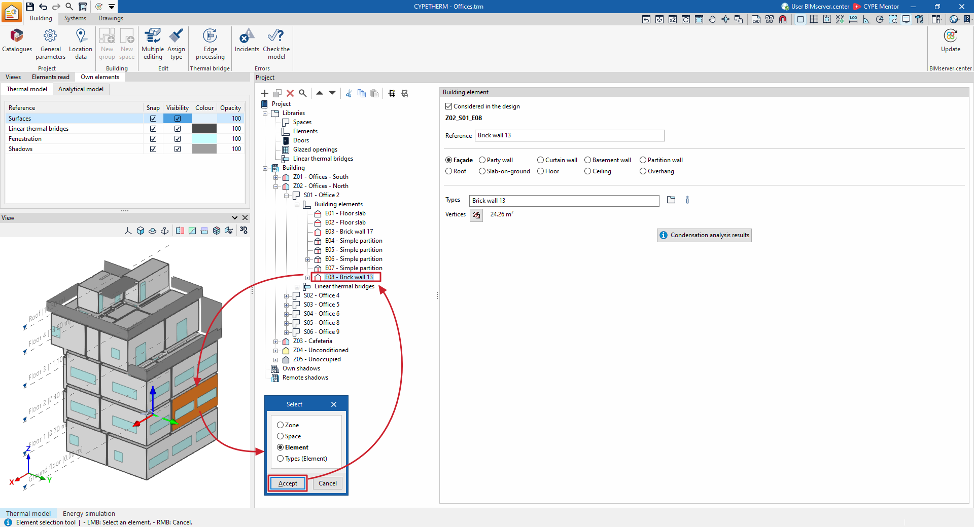
The selection and display of items in the "Project" tree and in the "View" pane are coordinated:
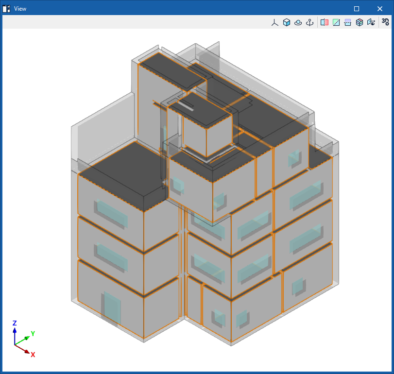
- The elements selected in the "Project" tree are highlighted in orange in the "View" (for example, a zone, a room or a specific structural element).
- Furthermore, if you left-click on a point on the model in the "View", the program opens a pop-up window where you can "Select" the "Zone", the "Enclosure", the "Element" or the "Type (Element)" to which the component highlighted in the view belongs. Doing so will expand the "Project" tree to the relevant level and select the component within it.
| More information: |
|---|
| In the top toolbar of the "View" panel, the program offers a range of tools for controlling the visibility of the 3D model, which are common to other views in CYPE programs and let you carry out operations such as changing the projection, rotating the view or creating sections. |