Introduction
CYPELEC is a program for designing low-voltage electrical systems used for drawing the system’s single-line diagrams and configuring the characteristics of the elements that make up the system.
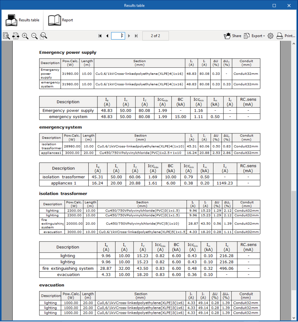
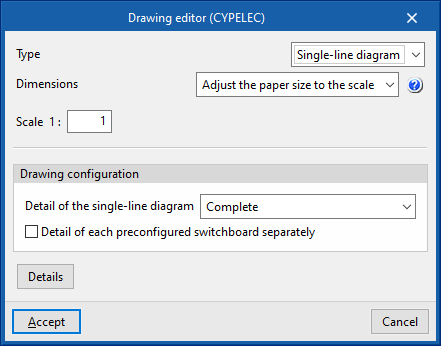
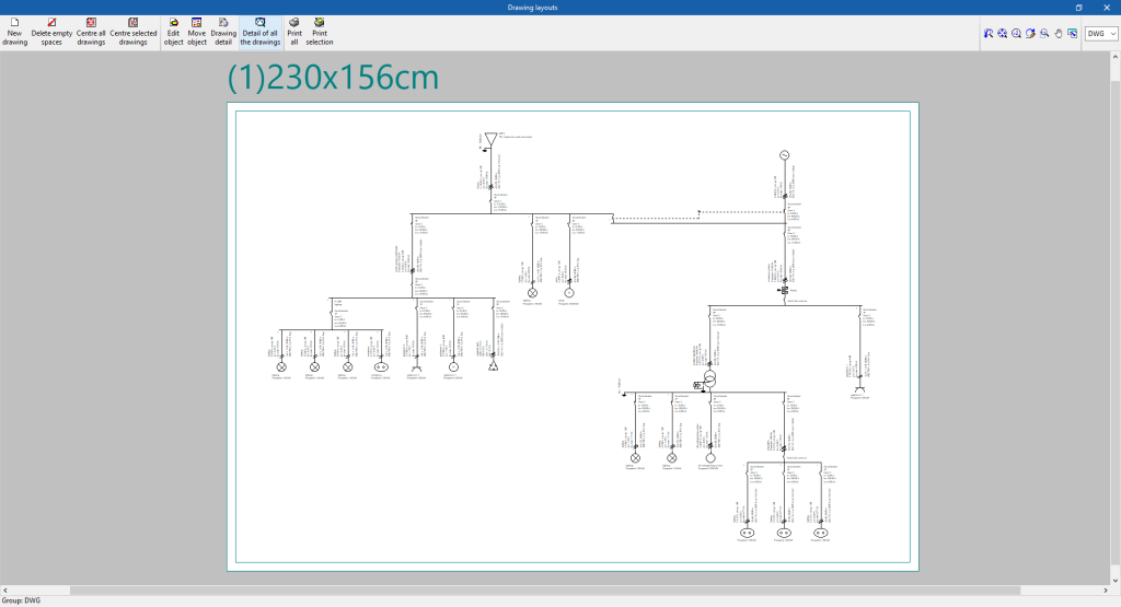
It carries out load flow and short-circuit calculations, with the possibility of editing all its elements with no power or line number restrictions. Its results output can be used to obtain single-line diagram drawings, justification reports, quantities tables and results tables.
The calculation checks carried out in the program are based on the specifications of different national and international codes.
This app is integrated into the Open BIM workflow via the IFC standard, which guarantees interaction with the rest of the tools.
Code selection
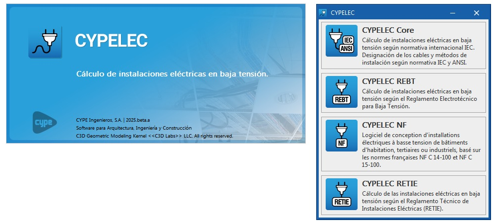
When CYPELEC is launched, a selection window appears where the option corresponding to the code to be applied in the analysis of the low-voltage electrical system must be indicated. This opens a work environment aimed at verifying that it complies with the codes.
The following environments are available: CYPELEC Core, CYPELEC REBT, CYPELEC NF and CYPELEC RETIE.
CYPELEC Core
Designs low-voltage electrical systems in accordance with international IEC standards. Cables and installation methods are designated according to IEC and ANSI standards.
CYPELEC REBT
Designs low-voltage electrical systems in accordance with the Spanish low-voltage electrical regulations Reglamento Electrotécnico para Baja Tensión (REBT).
CYPELEC NF
Designs low-voltage electrical systems in accordance with the French NF C 14-100 and NF C 15-100 standards.
CYPELEC RETIE
Designs low-voltage electrical systems in accordance with the Colombian regulations for electrical installations Reglamento Técnico de Instalaciones Eléctricas (RETIE).
Workflows supported by the program
As an Open BIM tool connected to the BIMserver.center platform, CYPELEC offers different workflow options.
Data entry
Free definition
- Defining the system, its elements and its characteristics by entering them freely in CYPELEC.
Importing BIM models
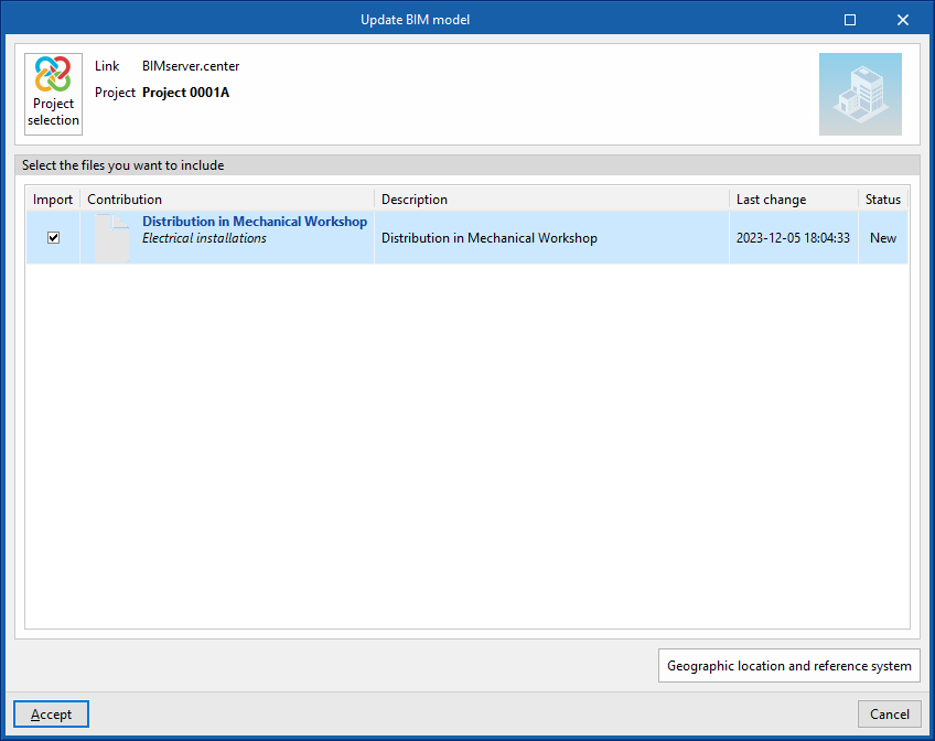
If the CYPELEC job is linked to a BIM project on the BIMserver.center platform, the following can be carried out:
- Import the content of switchboards and sub-switchboards from CYPELEC Distribution in order to use them in the process of automatic generation of lines and circuits in CYPELEC:
- Import models from CYPELEC Distribution
Data output
- Exporting reports to HTML, DOCX, PDF, RTF and TXT formats.
- Exporting drawings to DXF, DWG and PDF formats.
- Exporting the information contained in CYPELEC to the BIMserver.center platform using IFC formats. This allows the information to be viewed by authorised project participants. The information generated by CYPELEC can be used by the following programs:
- CYPELEC Multiline
Automatically generates the multiline diagram. - CYPELEC Networks
Receives the total power of the low voltage system and considers it as a point load for network analysis. - Open BIM Cable Routing
Reads the information on the single-line diagram of the electrical system. - Open BIM Switchboard
Allows users to import the distribution of lines and their assigned protections to create the distribution of protection elements inside the switchboard or cabinet.
- CYPELEC Multiline
Work environment
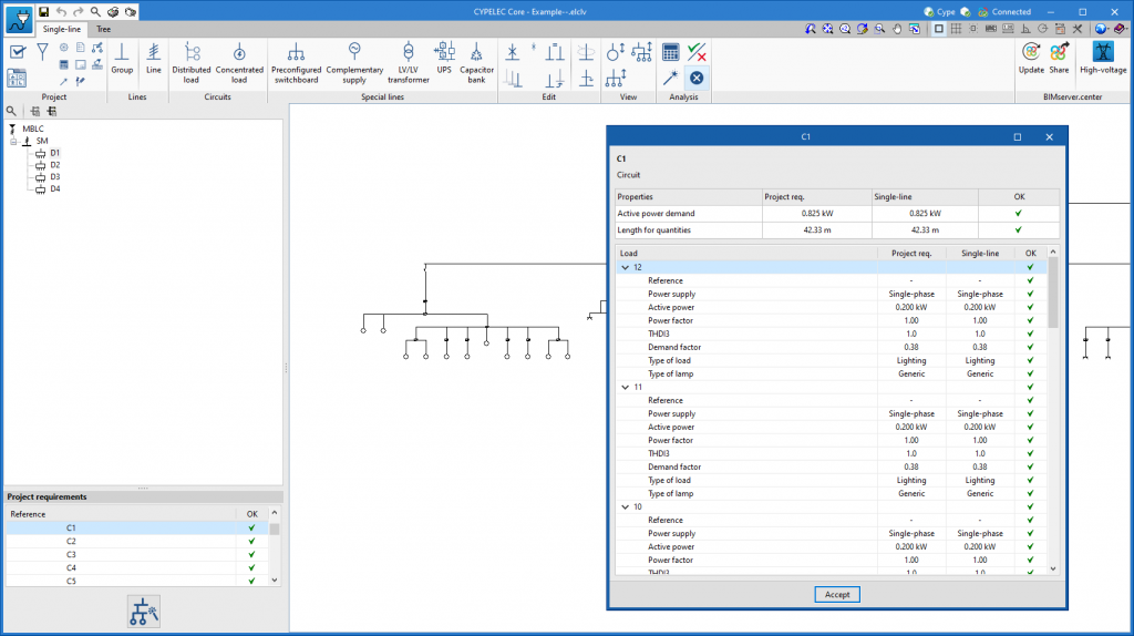
The program interface has two tabs at the top that allow users to access work environments that represent the system differently: "Single-line" and "Tree". Both work environments can be used to define the low-voltage electrical system, as the information entered is shared between the two tabs.
"Single-line" tab
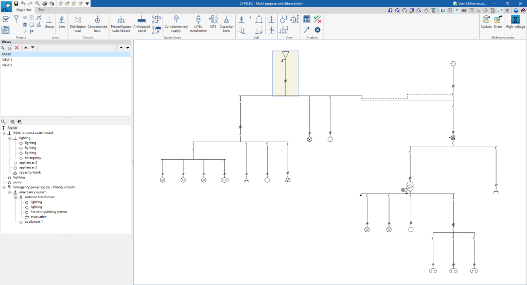
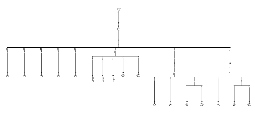
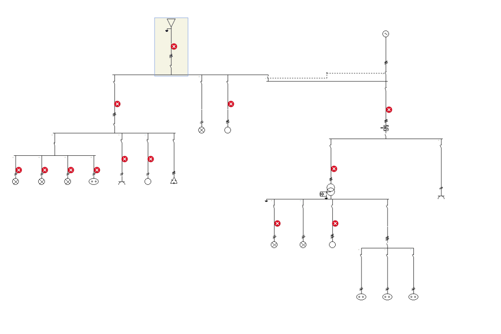
When starting, the tab activated by default is the "Single-line" tab. This presents a work environment that allows users to design and analyse the low-voltage electrical system by directly viewing and editing its single-line diagram.
This tab displays the following:
- A top toolbar containing the tools for managing the general conditions, supply and other project options, such as options for entering and editing lines and circuits, and special switchboard and lines, for using the editing and viewing tools, and for carrying out the analysis, checking and design of the system.
- The single-line diagram display area, on the right-hand side of the screen, where the lines and components of the electrical system can be selected, viewed and edited.
- On the left-hand side, a tree structure of the lines and circuits making up the electrical system, which can be expanded or collapsed.
Also, by double-clicking on a line in the tree diagram, it is possible to access its editing panel.
"Tree" tab
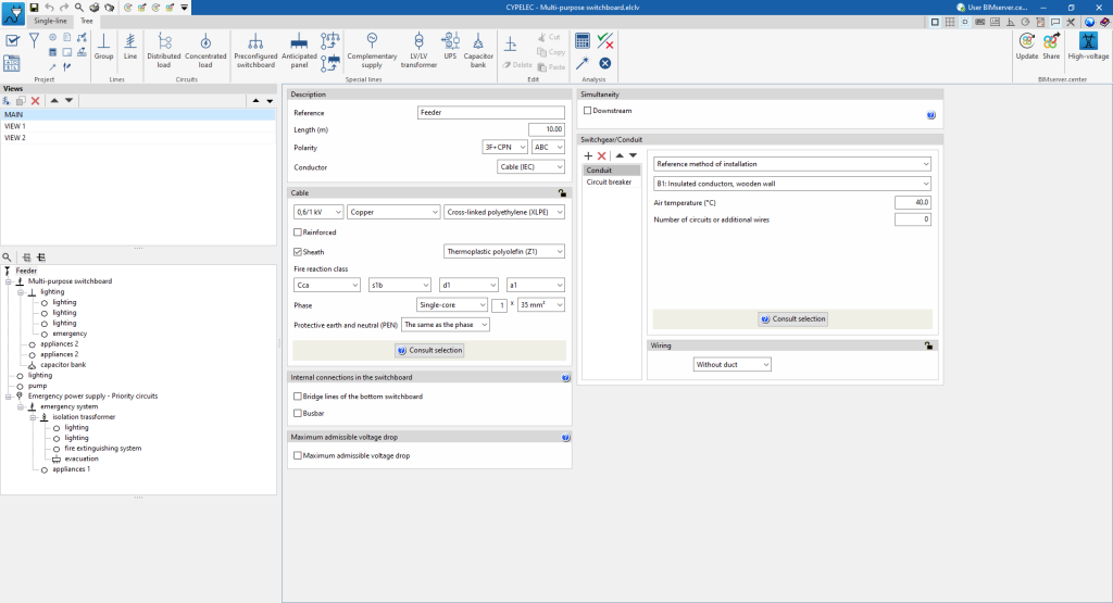
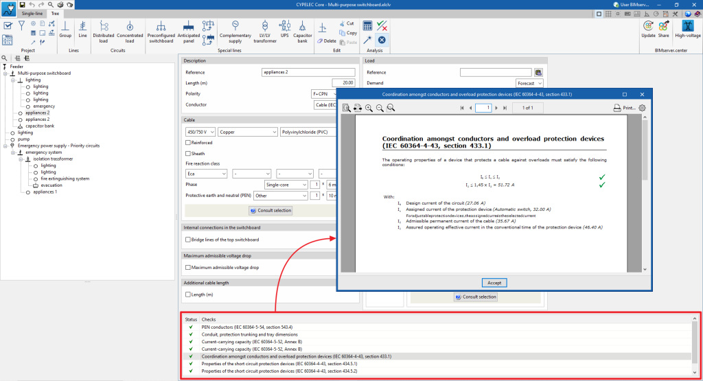
On the other hand, the "Tree" tab presents a work environment that allows users to design and analyse the low-voltage electrical system by directly accessing the panels for defining the lines and components from the project's navigation tree diagram.
This tab displays the following:
- A top toolbar containing the tools for managing the general conditions, supply and other project options, such as options for entering and editing lines and circuits, and switchboards and special lines, for using the editing tools and for analysing, checking and designing the system.
- The data editing panels of the lines and components of the electrical system, on the right-hand side of the screen.
- On the left-hand side, a tree structure of the lines and circuits that make up the electrical system can be expanded or contracted.
Data input and output sequence for the implementation of circuit and load distribution in electrical systems
The design of low voltage electrical systems can be carried out in the program by means of the following input and output sequence:
- Starting the program and selecting the work environment and regulations.
- Creating a new job (from "File", "New").
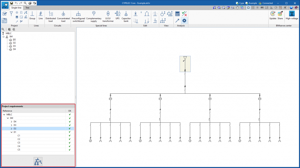
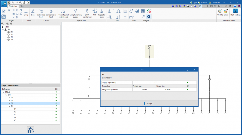
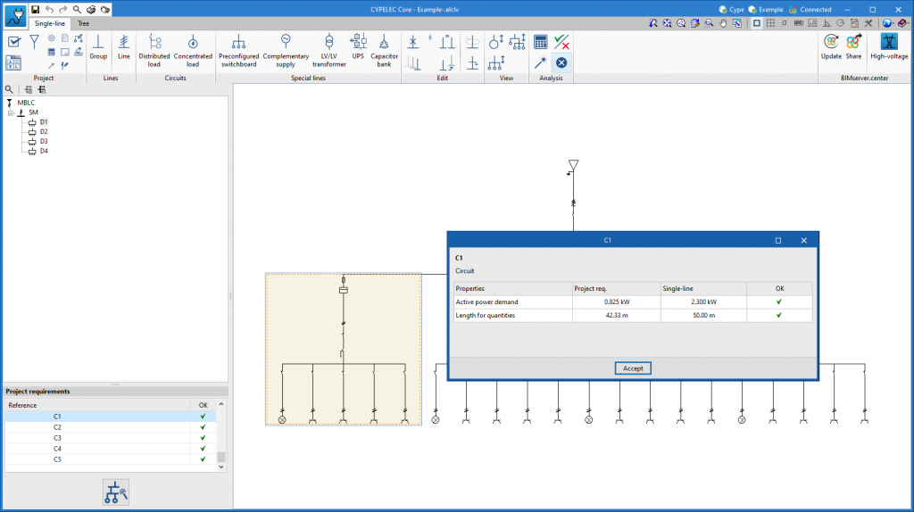
- (Optional) Linking to BIMserver.center and importing project requirements from the load distribution and circuits read from the BIM model.
- Setting the general options (from "Project, "General conditions").
- Configuration of the supply (from "Project", "Supply").
- (Optional) Defining types of elements (from "Project", "Element library").
- Reviewing the configuration, analysis and design options (from "Project", "Configuration"/"Analysis options"/"Design options").
- Defining and entering the elements of the single-line diagram of the low-voltage electrical system. This can be done in several ways:
- (Optional) Generating the single-line diagram from the project requirements in case they have been imported from the BIM model ("Generate a single-line diagram that meets the project requirements" option on the left-hand side).
- Defining and entering and/or revising the schematic elements manually:
- Defining and entering the hierarchy of groups and lines in the intermediate levels of the schematic (options in the "Lines" group).
- Defining and entering the circuits at the final levels of the schematic (options in the "Circuits" group).
- (Optional) Defining and entering the special lines of the schematic (options of the "Special lines" group).
- Analysing or designing the installation, consulting the results on screen and in the results reports (options in the "Calculation" group).
- Obtaining reports and drawings (from "File", "Reports/ Drawings").
- Exporting to BIMserver.center (from "BIMserver.center", "Share").
Defining the project characteristics
In the "Project" group of the main toolbar, in either the "Single-line" tab or the "Tree" tab, the following project data can be defined:

These options allow users to set the project's general characteristics, the supply conditions and the libraries of elements used, to adjust the analysis and design, and to adjust the presentation of the information on the screen and the drawings.
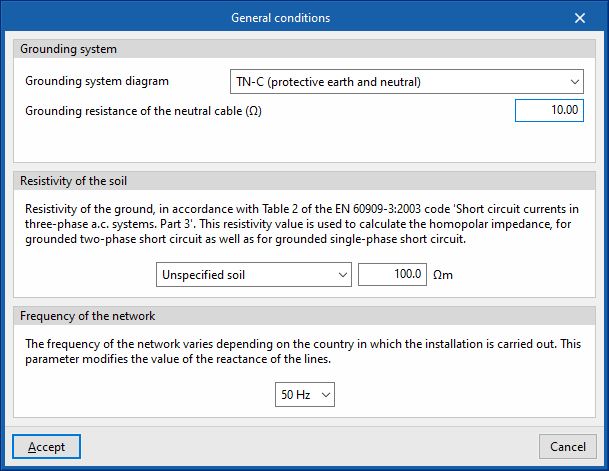
General conditions
When clicking on this button, a panel is displayed where the general conditions of the job can be established, which will be used to determine the starting points for the analyses to be carried out by the program.
Grounding system
Allows users to define the grounding system diagram and the parameters that characterise it:
- Grounding system diagram
- TT (neutral to ground)
- TN-S (grounded neutral)
- TN-C-S (protective earth and neutral)
- TN-C-S (protective earth and neutral in a part of the diagram)
- IT (unearthed neutral)
- IT (impedant neutral)
- Grounding resistance of the exposed conductive parts (in TT and IT diagrams)
- Grounding resistance of the neutral cable (in TT, TN-S, TN-C and TN-C-S diagrams)
The values of the grounding resistance of the earth and neutral can be defined in the following ways:- User defined
The value of the grounding resistance is entered by the user. - Calculated
The wizard on the right is used to select a grounding system from those previously created in the "Element libraries" and to import the value of the calculated grounding resistance into it.
- User defined
- Neutral resistance (in IT diagrams)
Grounding resistance
The numerical values of the grounding resistance of the system can be imported from the BIM model based on the data entered in programs such as CYPELEC Grounding IEC and CYPELEC Grounding IEEE, and shared with the BIMserver.center project. The program updates the value of the grounding resistance of the exposed conductive parts or neutral cable, depending on the program that has generated the project's IFC:
- IFC generated by CYPELEC Grounding IEC
IFCs generated from programs that analyse low voltage grounding such as CYPELEC Grounding IEC update the grounding resistance of the exposed conductive parts. - IFC generated by CYPELEC Grounding IEEE
IFCs generated from programs that analyse high voltage grounding such as CYPELEC Grounding IEEE update the grounding resistance of the neutral cable.
Resistivity of the soil
This allows the resistivity of the ground to be defined according to Table 2 of the EN 60909-3: 2003 code "Short circuit currents in three-phase a.c. systems. Part 3". This value is used to calculate the homopolar impedance. The following can be defined:
- Type of soil (Unspecified soil; Granite; Rock; Stony ground; Pebbles, dry sand; Calcareous ground, damp sand; Agricultural soil; Clay, mud; Marshland)
- Resistivity of the soil (Ω⋅m)
Frequency of the network
This value varies depending on the country where the installation is carried out. The parameter entered modifies the reactance of the lines. This allows users to choose between the following frequencies:
- 50 Hertz
- 60 Hertz
The TN-C-S diagram is unique because the TN-C and TN-S diagrams are combined in a single system. The program carries out the special checks that this combination entails ("no TN-C scheme downstream of the TN-S scheme, no residual current device downstream of the connection of the protective earth conductor to the CPN conductor").
Supply
Type of supply
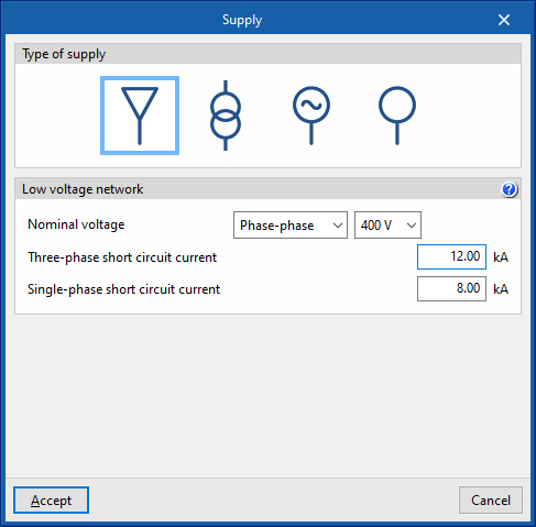
This dialogue box allows the program to define the type of main supply for the system. The following options are offered:
- Low voltage network
This allows a low-voltage network to be defined as the main supply. The nominal voltage to be used must be established, as well as the three-phase and single-phase short-circuit currents, from which the short-circuit impedances of the installation will be determined. Default indicative values are assigned, which are normally provided by the distribution company, but which can be adjusted. These values are:- Rated voltage (Phase-neutral / Phase-phase) (V)
- Three-phase short circuit current (kA)
- Single-phase short circuit current (kA)
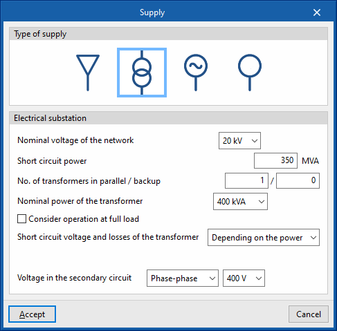
- Electrical substation
Allows users to define a transformer substation as the main supply. The following data can be indicated:- Nominal voltage of the network (kV)
- Short circuit power (MVA)
- No. of transformers in parallel /backup
- Nominal power of the transformer (kVA)
- Consider operation at full load (optional)
With this option, the calculation current of the transformer line is obtained from its rated power, instead of taking the power of the loads it feeds. - Short circuit voltage and losses of the transformer (Depending on the power / User-defined)
- Voltage in the secondary circuit (Phase-neutral / Phase-phase) (V)
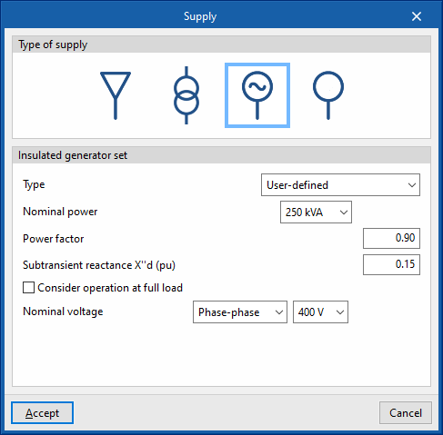
- Insulated generator set
Allows users to define a stand-alone generator set as the main supply. The following data can be entered:- Type:
- User-defined:
- Nominal capacity (kVA)
- Power factor
- Subtransient reactance X''d (pu)
- Manufacturer generator set
- User-defined:
- Consider operation at full load (optional)
- Rated voltage (Phase-neutral / Phase-phase) (V)
- Type:
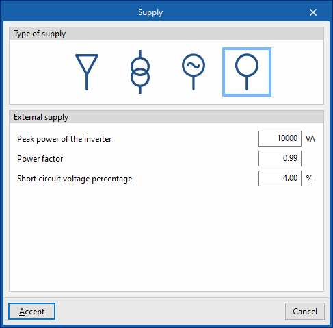
- External supply
With this option, any type of main supply can be defined generically. The following data can be entered:- Peak power of the inverter (VA)
- Power factor
- Short circuit voltage percentage (%)
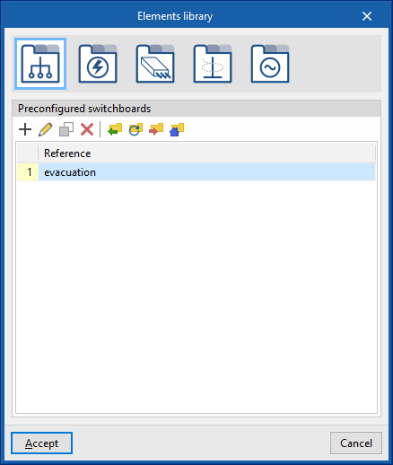
Elements library
Allows users to check and edit the libraries of the following elements of the system:
- Preconfigured switchboards
- Types of receivers
- Prefabricated conduits
- Groups of lines
- Manufacturer generator sets
- Grounding system
Each of the element types can be imported and exported to files on disk in a single command. After selecting the elements to be imported, they will be added to the library and placed after the existing ones or, if they are the same, they will replace them.
Manufacturer catalogues
Manages the manufacturer catalogues available in the project, their downloads and updates.
Configuration
Current calculation
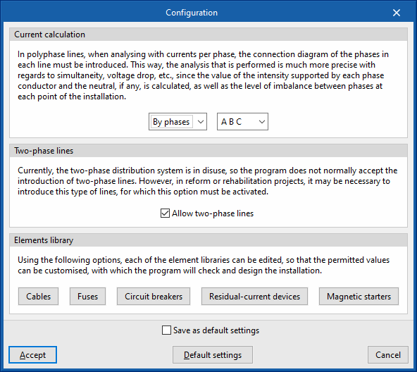
Allows users to choose between a balanced or phase-by-phase calculation of currents:
- Balanced
In this mode, the three single phase phases attached to a three-phase line are assumed to be balanced. This way of proceeding may be more convenient for design purposes, but it is only an approximation, as total balance is very difficult to achieve. - By phases
This mode offers users the possibility of designing the system with an unbalanced phase distribution. The program allows the nomenclature of the phases of a three-phase electrical system to be selected in several ways:- R S T / A B C / L1 L2 L3 / U V W / X Y Z / R Y B / R G B
When selecting "By phases", for polyphase lines, the phase connection diagram for each line must be selected.
This way, the analysis is more precise, since the current value in each phase conductor and the neutral cable is calculated, as well as the imbalance level between phases at any point of the system if it exists. The currents flowing through each of the phases and the neutral cable to compensate for the imbalance between them will be taken into account, these currents will be considered when correctly designing the section of each conductor (including the neutral cable) and both the simple voltage drops (phase-to-neutral) and the compound voltage drops (phase-to-phase) will be calculated.
Two-phase lines
Allows users to activate the possibility of defining two-phase lines in the system. Although the two-phase distribution system is no longer in use, this can be useful in refurbishment or renovation projects.
- Allow two-phase lines (optional)
This ensures that, both in the supply line and the intermediate lines, the three-wire distribution is activated (2F + N or 2F + CPN), and that in the final circuits with loads the two-wire supply is activated (2F or 2F+CPN), as well as allowing the definition of two-phase electrical receivers. If the calculation is made "By phases", the program will also allow the two-phase selection in RS, ST or TR.
Elements library
Allows users to customise the permitted values of the following elements to allow their definition in the model or to use them for design purposes. The parameter selection in the line editing panels is conditioned by the editing of the element libraries so that the elements that have not been selected will remain hidden in the line editing:
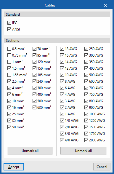
- Cables
- Standard (IEC / ANSI)
- Sections
Cables under the IEC standard in mm2 can be used, or cables under the ANSI standard in American Wire Gauge (AWG).
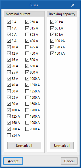
- Fuses
- Nominal current
- Breaking capacity
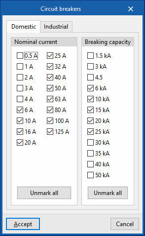
- Circuit breakers
- “Domestic” tab
- Nominal current
- Breaking capacity
- “Industrial” tab
- Nominal current
- “Domestic” tab
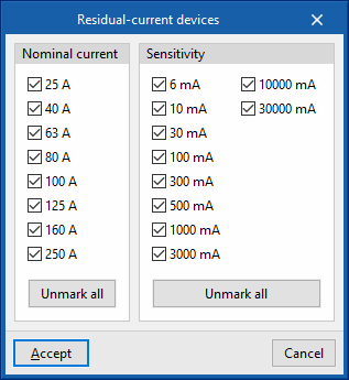
- Residual-current devices
- Nominal current
- Sensitivity
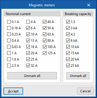
- Magnetic starters
- Nominal current
- Breaking capacity
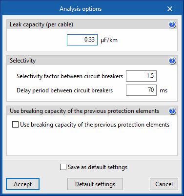
Analysis options
Leak capacity (per cable)
This section enters the earth leakage capacitance value of a cable (μF/km). This value is used to estimate the leak currents when testing the sensitivity of the residual current circuit breakers installed as protection against indirect contacts.
Selectivity
To carry out the selectivity check, the program allows the following parameters to be defined:
- Selectivity factor between circuit breakers
- Delay period between circuit breakers (ms)
The selective action between the overcurrent protection devices is checked by analysing their corresponding firing curves (curve selectivity). The firing times and the currents for which the disconnection of the devices connected in series takes place must have, depending on the type of device, the corresponding safety interval.
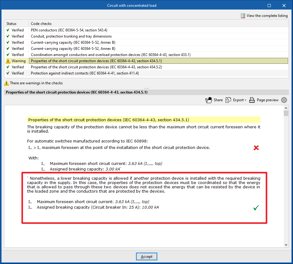
Use breaking capacity of the previous protection elements
IEC 60364-4-43, section 434.5.1. allows a lower breaking capacity of the load zone protective device if another upstream protective device with the required breaking capacity is installed on the supply side.
To consider this, the following options can be marked:
- Use breaking capacity of the previous protection elements (optional)
- Of the fuses (optional)
- Of the circuit breakers (optional)
In this case, the characteristics of the two devices must be coordinated (e.g. by applying screening techniques) so that the energy allowed to pass through these two devices does not exceed the energy that can be withstood without damage by the device in the load zone and the conductors protected by the devices.
The check report will include a comment if this option has been used.
Design options
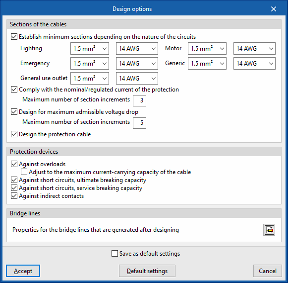
Sections of the cables
PAllows users to configure the criteria to be considered in the automatic design process carried out by the program for the cable sections. Users can carry out the following:
- Establish minimum sections depending on the nature of the circuits (optional)
- Lighting
- Emergency
- General use outlet
- Motor
- Generic
- Comply with the nominal/regulated current of the protection (optional)
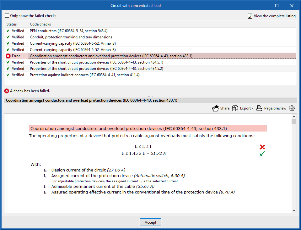
Allows the cable section to be increased to comply with the rated current or regulated current of the protection (IB≤In≤Iz check), by specifying the maximum number of section increments that the program will perform automatically:- Maximum number of section increments
- Design for maximum admissible voltage drop (optional)
Design for maximum admissible voltage drop, specifying the maximum number of section increments that the program is to perform automatically. This criteria considers the limitation of the "Maximum admissible voltage drop" imposed by the user in the edition panel of the groups, lines and circuits:- Maximum number of section increments
- Design the protection cable (optional)
Protection devices
Allows users to configure the criteria to be considered in the automatic design process carried out by the program for the installation's protection devices. The following options can be activated:
- Against overloads (optional)
Designs the overload protection devices, with the added possibility of adjusting the rated current of the protection to the maximum admissible current of the cable:- Adjust to the maximum current-carrying capacity of the cable (optional)
- Against short circuits, ultimate breaking capacity (optional)
Designs short-circuit protection devices to ultimate breaking capacity. - Against short circuits, service breaking capacity (optional)
Designs short-circuit protection devices to service breaking capacity. - Against indirect contacts (optional)
Designs the rating of protective devices against indirect contacts.
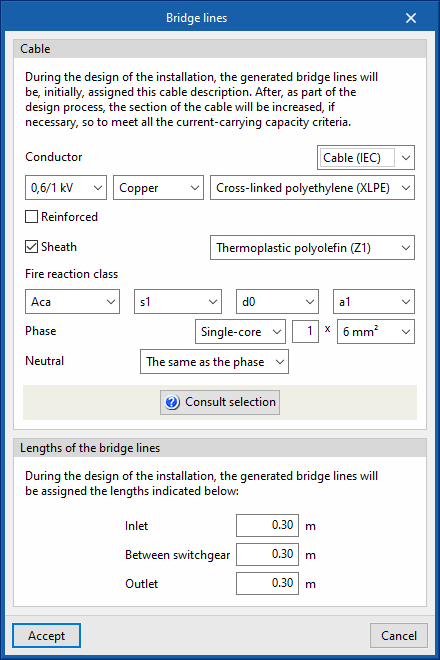
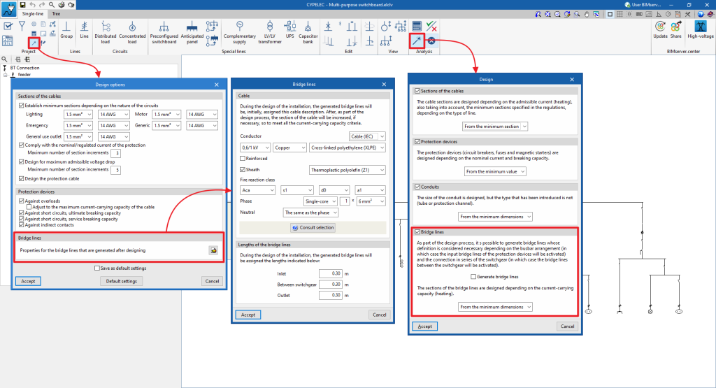
Bridge lines
Allows users to define the characteristics of the bridge lines generated when designing the system.
- Properties for the bridge lines that are generated after designing
- Cable
When designing the system, the bridge lines generated are assigned the cable description selected in this section. Subsequently, as part of the design process, the cable section shall be increased, if necessary, to meet the current-carrying capacity criteria. - Lengths of the bridge lines
When designing the system, the generated bridge lines shall be assigned the lengths indicated below:- Inlet
- Between switchgear
- Outlet
- Cable
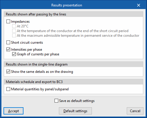
Results presentation
Allows users to configure the presentation of the results obtained by the program in the following ways:
- Results shown after passing by the lines
- Impedances (optional)
- At 20 ºC (optional)
- At the temperature of the conductor at the end of the short circuit period (optional)
- At the maximum admissible temperature in permanent service of the conductor
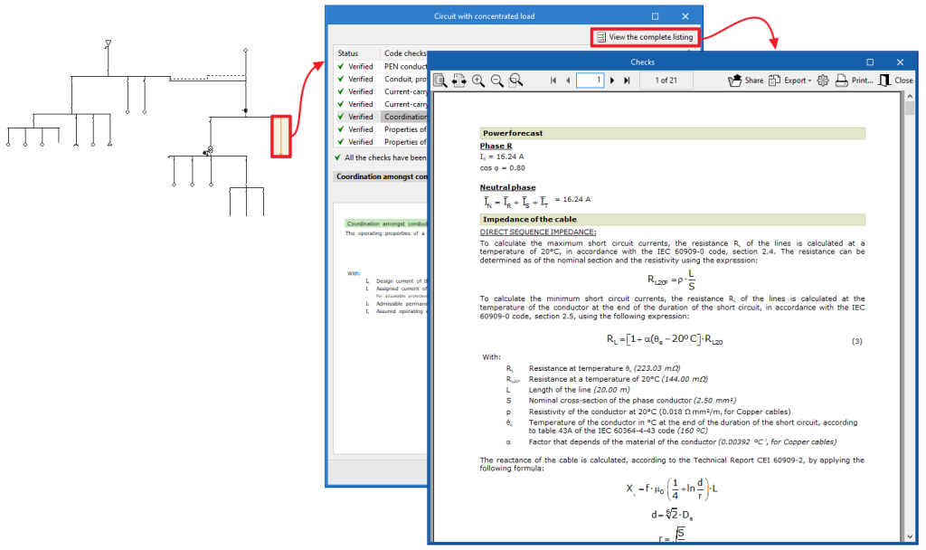
- Short circuit currents (optional)
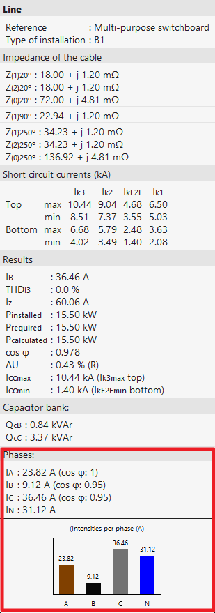
- Intensities by phase (optional)
These options are useful when working in the current per-phase calculation mode.- Graph of currents per phase (optional)
- Impedances (optional)
- Results shown in the single-line diagram
- Show the same details as on the drawing (optional)
- Material schedule and export to BC3
- Material quantities by panel/subpanel (optional)
With this option, users can launch the material table report not only in a global form for the project but also classified by panels and subpanels.
- Material quantities by panel/subpanel (optional)
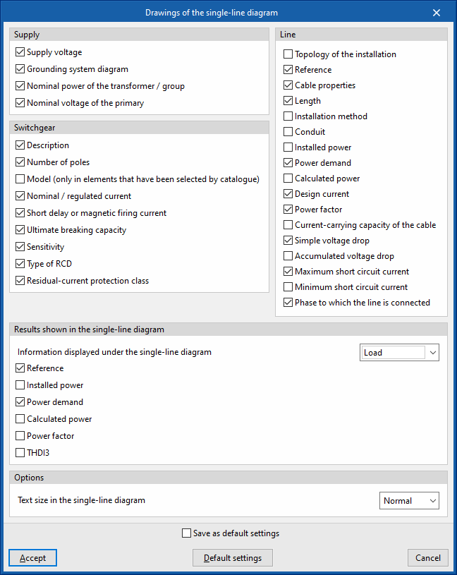
Drawings of the single-line diagram
Allows you to activate or deactivate the information shown in the single-line diagram drawings for each of the following elements:
- Supply (Supply voltage, Grounding system diagram, Nominal power of the transformer / group, Nominal voltage of the primary)
- Load (Reference, Installed power, Power demand, Calculated power, Power factor, THDI3)
- Switchgear (Description, number of poles, Model (only in elements that have been selected by catalogue), Nominal / regulated current, Short delay or magnetic firing current, Ultimate breaking capacity, Sensitivity, Type of RCD, Residual-current protection class)
- Line (Topology of the installation, Reference, Cable properties, Length, Installation method, Conduit, Installed power, Power demand, Calculated power, Design current, Power factor, Current-carrying capacity of the cable, Simple voltage drop, Accumulated voltage drop, Maximum short circuit current, Minimum short circuit current, Phase to which the line is connected)
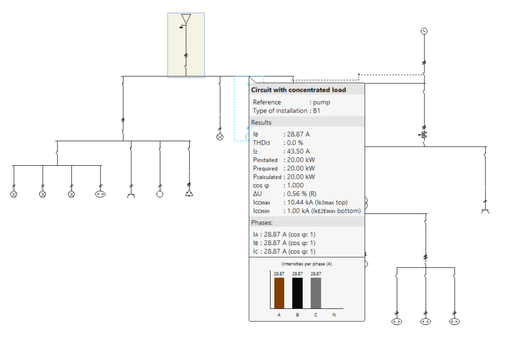
Users can also modify and configure the results information displayed at the bottom of the single-line diagram. This information can be displayed under the electrical load or as a properties table. To update these values after modifying the editing data, users must click on the "Analysis" option:
- Results shown in the single-line diagram
- Information displayed under the single-line diagram
- Load (Reference, Installed power, Power demand, Calculated power, Power factor, THDI3)
- Properties table (Reference, Installed power, Power demand, Calculated power, Nominal voltage, Design current, Current-carrying capacity of the cable, Cable properties, Length, Simple voltage drop, Accumulated voltage drop)
- Information displayed under the single-line diagram
Finally, the program allows users to configure the following options:
- Options
- Text size in the single-line diagram
Single-line diagram
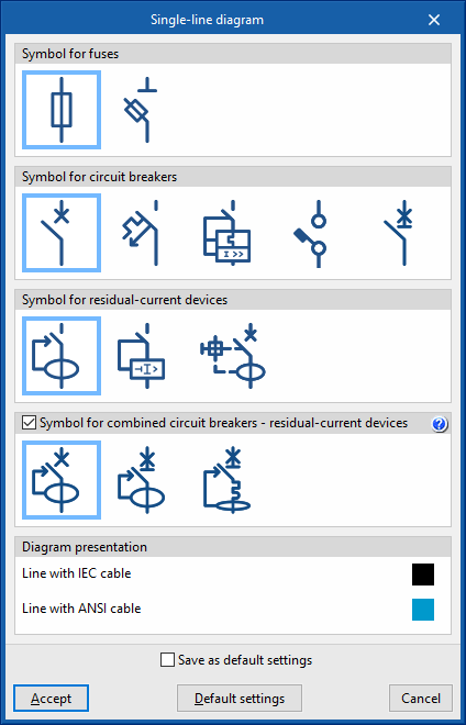
Allows users to configure the symbology used by the program in the single-line diagram for different types of protections, as well as the lines' representation colour:
- Symbol for fuses
- Symbol for circuit breakers
- Symbol for residual-current devices
- Symbol for combined circuit breakers - residual-current devices (optional)
This option allows the combined combined circuit breaker - residual-current device to be represented by a single symbol combining both features, instead of being represented by two separate symbols. - Diagram presentation
This allows the colour of the lines to be chosen according to the cable used. Lines with mm2 or AWG wires can thus be distinguished in the same electrical system:- Line with IEC cable
- Line with ANSI cable
Bridge lines
Reference installation method
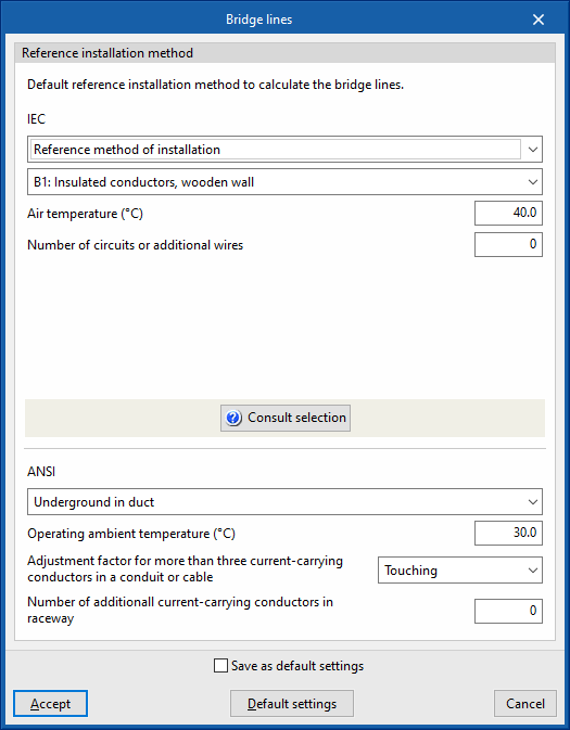
This section defines the default reference installation method for analysing bridge lines, specifying its characteristics for both IEC and ANSI cables.
- IEC:
- Reference method of installation / IEC 60364-5-52, Table A.52.3
- Ambient temperature
- Number of circuits or additional wires
- ANSI:
- Reference method of installation
- Operating ambient temperature
- Adjustment factor for more than three current-carrying conductors in a conduit or cable
- Number of additional current-carrying conductors in the same conduit
Predefined lines/circuits in the toolbar
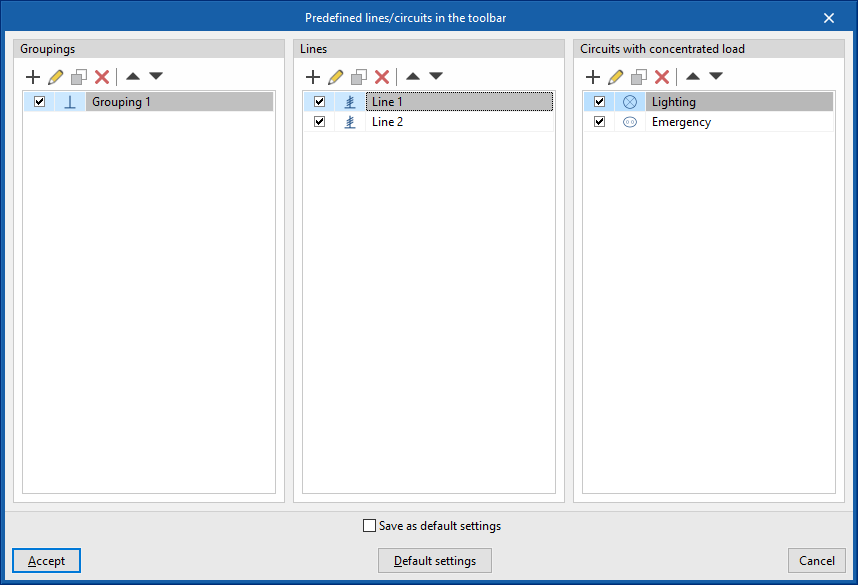
This option provides several tables in which lines or circuits with predetermined properties can be defined and configured, indicating an icon and a reference for each one of them.
These predefined lines or circuits will appear as new options in the top toolbar of the program interface. This means that more or fewer buttons with their corresponding icons will appear on the toolbar depending on the user's settings.
The aim of this feature is to speed up the entry of installation data, enabling quick access to be generated for the most frequently used lines or circuits.
Predefined lines or circuits can be defined for the following types of elements:
- Groupings
- Lines
- Circuits with concentrated load
Entering groups and lines
In the "Lines" group of the main toolbar, either in the "Single line" tab or in the "Tree" tab, the following elements can be defined and entered:

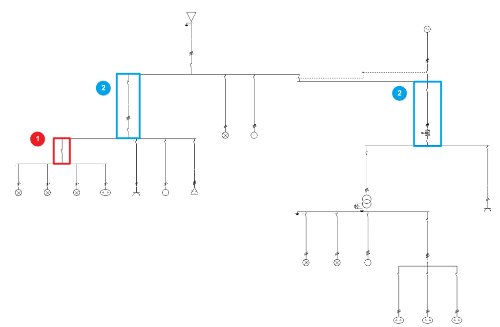
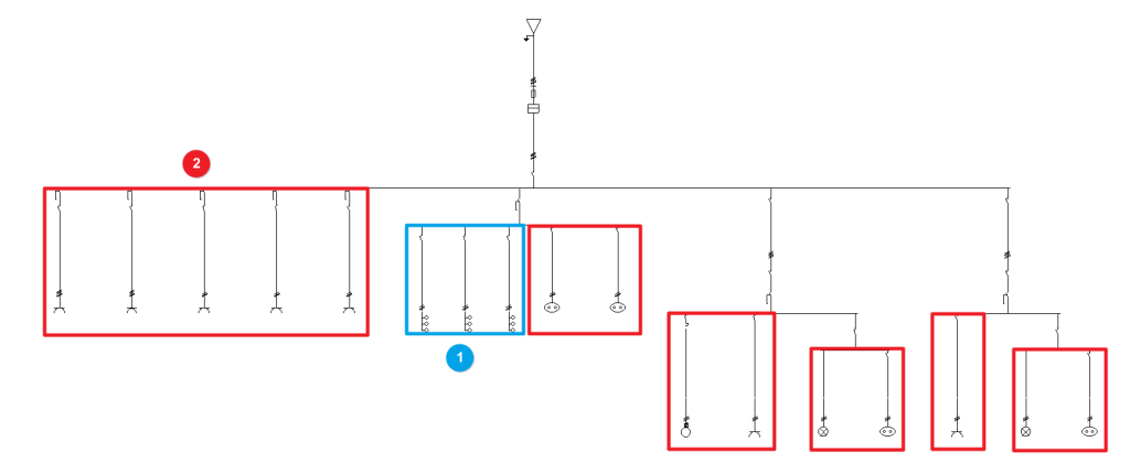
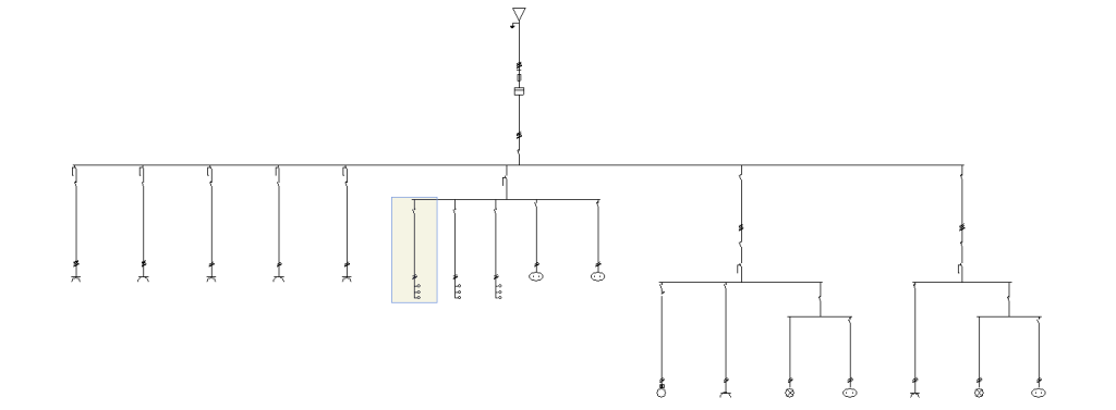
The program is highly versatile in the layout of electrical system diagrams in terms of the number of elements, nesting of levels and types of load. The groups and lines are organised based on the multilevel supply and collect the distributed or concentrated load circuits, downstream:
- Group (1)
- Line (2)
Group
Allows users to define and enter a group of different loads using one or more protection elements but without a conduit. No length value definition is required. Clicking on the option opens the "Group" window, which displays the following configuration options:
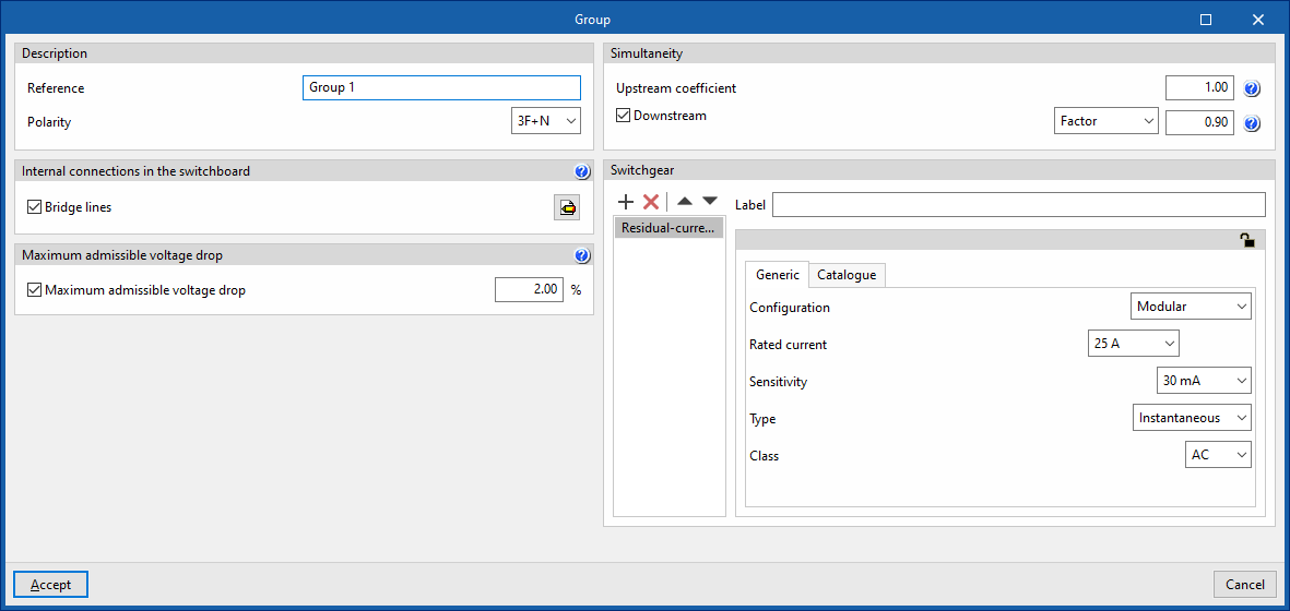
- Description
- Reference
- Polarity
- Internal connections in the switchboard
- Bridge lines (optional)
By activating this option, the program allows users to enter and consider bridge lines in the group. It opens the "Bridge lines" window, with the following options:- Bridge lines to consider and their lengths
- Inlet (optional)
- Between switchgear (optional)
- Outlet (optional)
- Conductor (optional)
- Cable
- Reference installation method
- Specific reference installation method (optional)
- Bridge lines to consider and their lengths
- Bridge lines (optional)
- Maximum admissible voltage drop
- Maximum admissible voltage drop (optional)
With this option, users can set a maximum admissible voltage drop value. The program will check and design the line according to the value entered.
- Maximum admissible voltage drop (optional)
- Simultaneity
These options allow users to define the simultaneity of the lines. - Switchgear
Allows users to enter the switchgear for the group. It may be one of the following types:- Circuit breaker
- Fuse
- Residual-current device
- Surge protector for transient overvoltages
- Sectionaliser
- Contactor
- Network analyser
Line
Allows users to define and enter a line in the model. Clicking on the option opens the "Line" window, which displays the following configuration options:
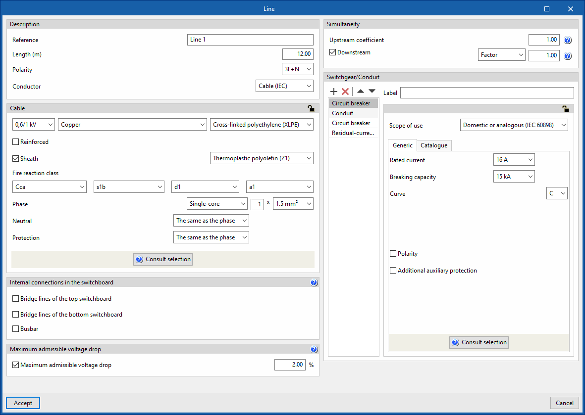
- Description
- Reference
- Length (m)
- Polarity
- Conductor
- Cable
- Internal connections in the switchboard
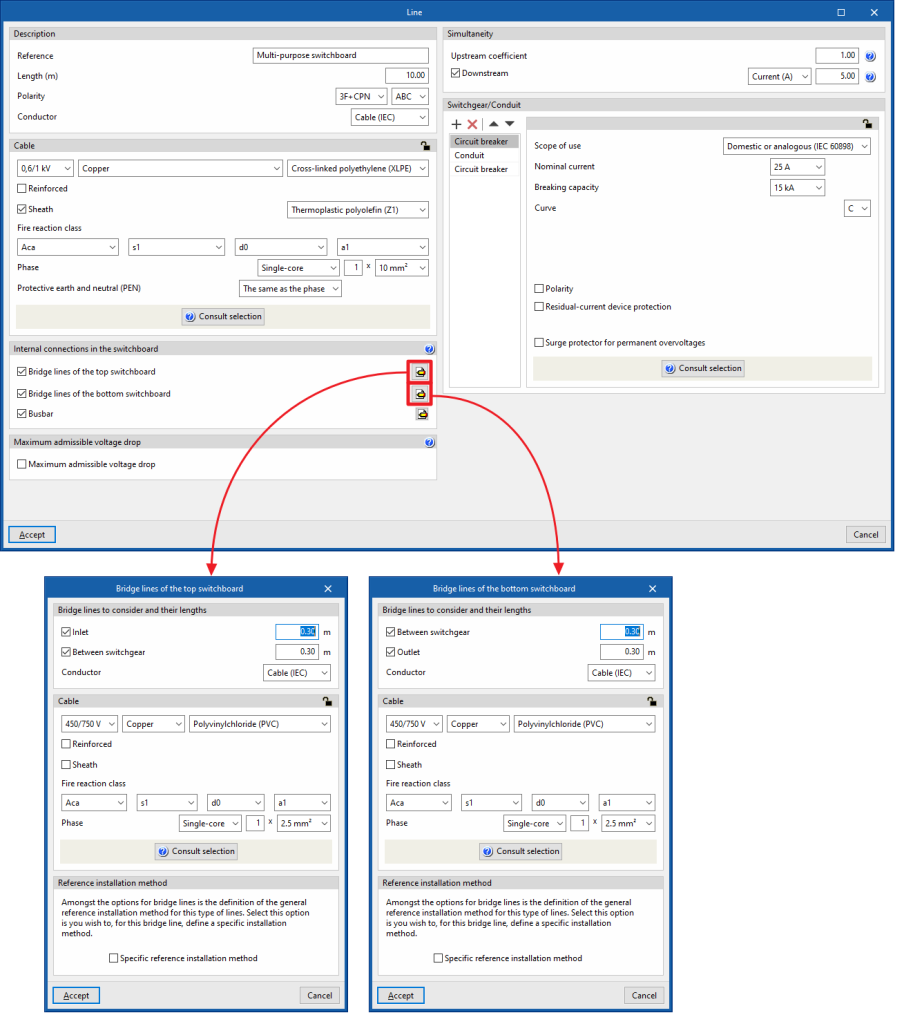
- Bridge lines of the top switchboard (optional)
By activating this option, the program allows users to enter and consider bridge lines of the top switchboard on the line. It opens the "Bridge lines of the top switchboard" window, with the following options:- Bridge lines to consider and their lengths
- Inlet (optional)
- Between switchgear (optional)
- Conductor
- Cable
- Reference installation method
- Specific reference installation method (optional)
- Bridge lines to consider and their lengths
- Bridge lines of the bottom switchboard (optional)
By activating this option, the program allows users to enter and consider bridge lines of the bottom switchboard on the line. It opens the "Bridge lines of the bottom switchboard" window, with the following options:- Bridge lines to consider and their lengths
- Between switchgear (optional)
- Outlet (optional)
- Conductor
- Cable
- Reference installation method
- Specific reference installation method (optional)
- Bridge lines to consider and their lengths
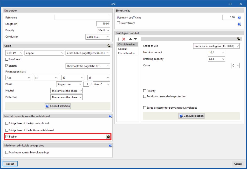
- Busbar
By activating this option, the program allows users to enter and consider busbars on the line.
- Bridge lines of the top switchboard (optional)
- Maximum admissible voltage drop
- Maximum admissible voltage drop (optional)
With this option, users can set a value for the maximum admissible voltage drop. The program will check and design the line according to the value entered.
- Maximum admissible voltage drop (optional)
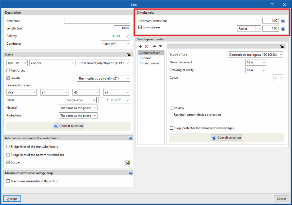
- Simultaneity
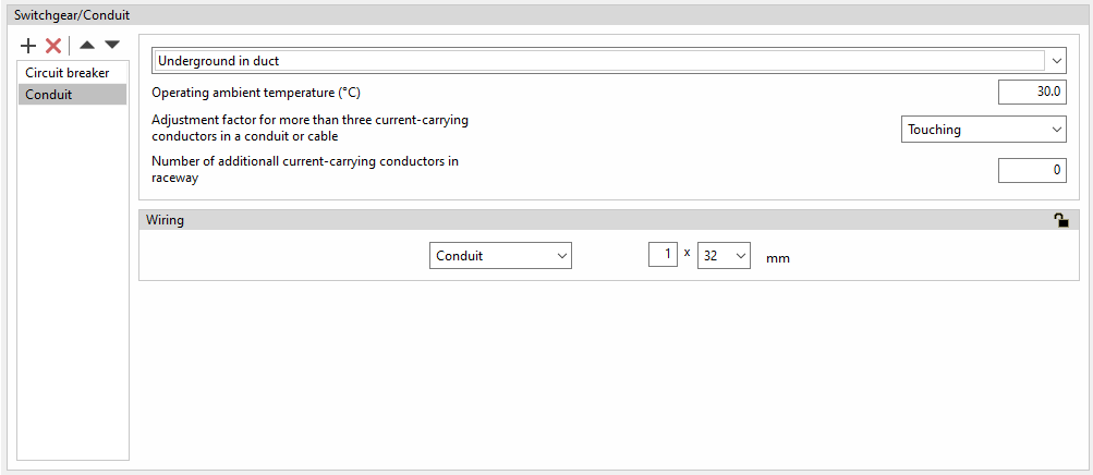
These options allow users to define the simultaneity of the lines. - Switchgear/Conduit
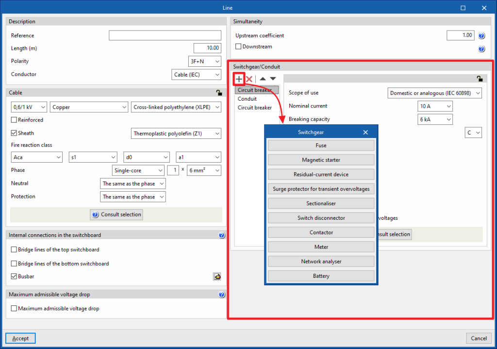
Allows the switchgear to be entered and the conduit of the line to be defined. This can be of the following types:- Circuit breaker
- Fuse
- Magnetic starter
- Residual-current device
- Surge protector for transient overvoltages
- Sectionaliser
- Switch disconnector
- Contactor
- Meter
- Network analyser
- Battery
Entering circuits
In the "Circuits" group of the main toolbar, either in the "Single-line" tab or in the "Tree" tab, the following elements can be defined and entered:

Both distributed and concentrated load circuits can be freely arranged in the single-line diagram on multiple levels:
- Circuits with distributed load (1)
- Circuits with concentrated load (2)
Circuit with distributed load
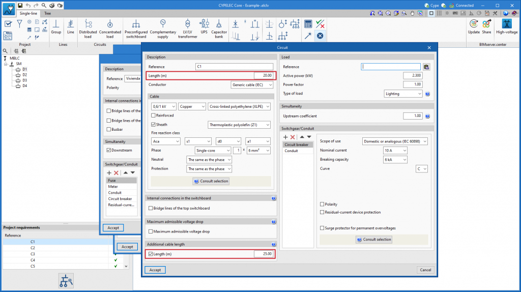
The "Distributed load" option allows users to define and enter a distributed load circuit. These circuits allow the load distribution to be detailed. Clicking on this option opens the "Circuit with distributed load" window, which displays the following configuration options:
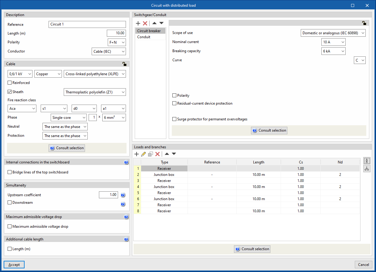
- Description
- Reference
- Length (m)
- Polarity
- Conductor
- Cable (IEC)
- Precast conduit
- Cable (ANSI)
- Cable
- Internal connections in the switchboard
- Bridge lines of the top switchboard (optional)
By activating this option, the program allows users to enter and consider bridge lines at the top of the line. It opens the "Bridge lines of the top switchboard" window, with the following options:- Bridge lines to consider and their lengths
- Inlet (optional)
- Between switchgear (optional)
- Conductor
- Cable
- Reference installation method
- Specific reference installation method (optional)
- Bridge lines to consider and their lengths
- Bridge lines of the top switchboard (optional)
- Simultaneity
These options allow users to define the simultaneity of the lines. - Maximum admissible voltage drop
- Maximum admissible voltage drop (optional)
With this option, users can set a maximum admissible voltage drop value. The program will check and design the line according to the value entered.
- Maximum admissible voltage drop (optional)
- Additional cable length
With this option, users can enter a value that complements the circuit's length to measure the cable's total length. This length can consider, for example, the connection between junction boxes and switches to complete the lighting points, or the junction boxes that the circuit may include in its installation that have not been considered for the sizing of the cable, but are considered for its total measurement:- Length (m) (optional)
For example, for a large installation (such as an industrial building or a hospital) where the lighting is to be divided into sectors and where it is more convenient to enter a distributed load block to copy it several times and then make minor modifications to each one of them.
- Switchgear/Conduit
Allows the switchgear to be inserted and the line conduit to be defined. This can be of the following types:- Circuit breaker
- Fuse
- Magnetic starter
- Residual-current device
- Surge protector for transient overvoltages
- Sectionaliser
- Switch disconnector
- Contactor
- Network analyser
- Capacitor
- Battery
- Loads and branches
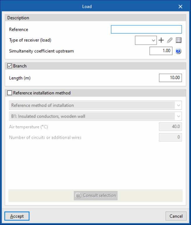
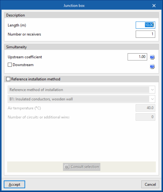
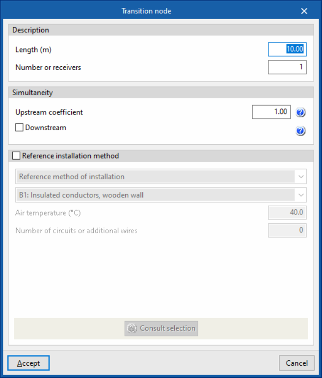
This table can be used to enter loads, junction boxes and transition nodes to model the geometry of the load distribution. Different reference installation methods can be defined for each of the sections that make up the conduit of a circuit with distributed load:- Load
- Description
- Reference
- Type of receiver (load)
- Simultaneity coefficient upstream
- Branch (optional)
- Length (m)
- Specific reference installation method (optional)
- Description
- Junction box
- Description
- Length (m)
- Number of receivers
- Simultaneity
- Upstream coefficient
- Downstream (optional)
- Specific reference installation method (optional)
- Description
- Transition node
- Automatic generation of loads and derivations
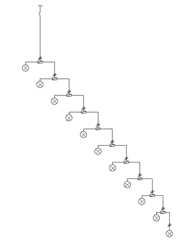
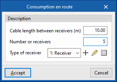
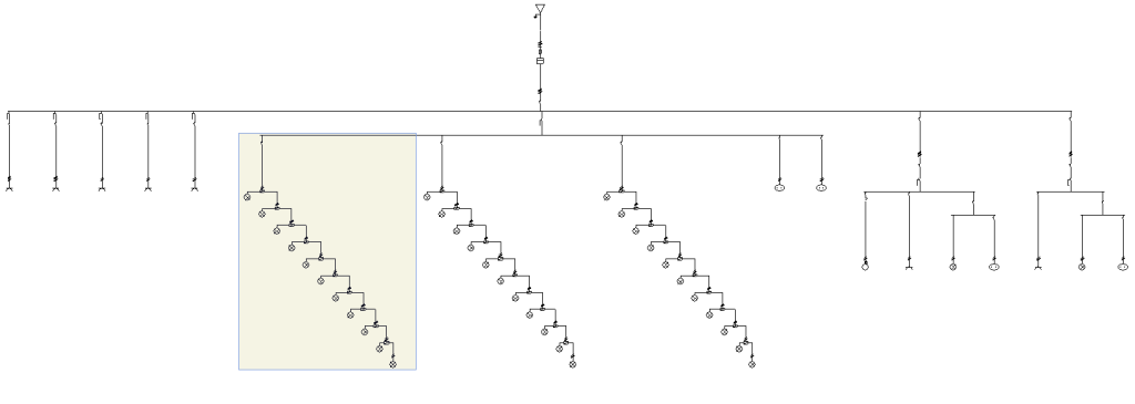
The program has help assistants on the right-hand side to automatically generate the set of loads, junction boxes and transition nodes of the distributed load circuit in the following cases:- Consumption en route
This generates a distributed en-route load, using junction boxes to distribute the load across the receivers along the route spaced a distance equal to the indicated length:- Cable length between receivers (m)
- Number of receivers
- Polarity (only in three-phase supply lines)
- Type of receiver (load)
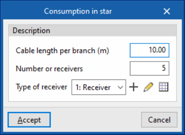
- Consumption in star
This generates a star-shaped distributed load. From the initial node, it generates as many branches as there are receivers.- Cable length per branch (m)
- Number or receivers
- Polarity (only in three-phase supply lines)
- Type of receiver (load)
- Consumption en route
- Load
The load definition panels, junction boxes and transition nodes look as follows:
On the other hand, the automatic load generation assistants and derivations in the cases of consumption en route and consumption in star are shown as follows:
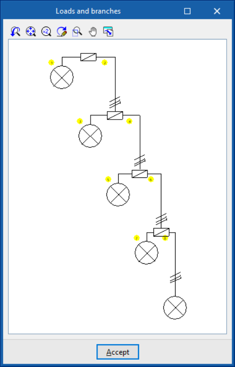
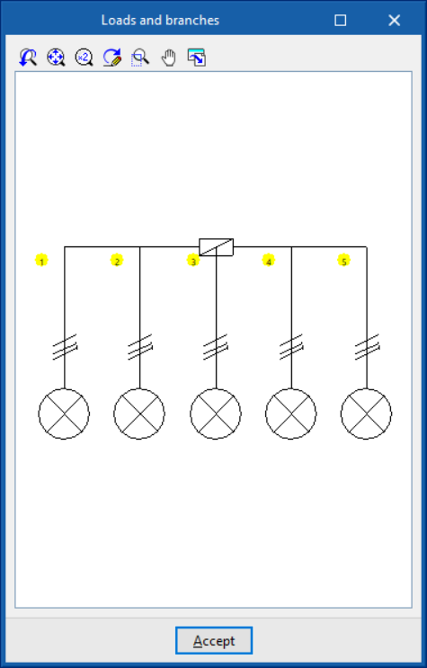
Using "Check selection", a representation of the load distribution diagram in the circuit is displayed. The location of the junction boxes used in distributed load circuits is represented by their standardised icon:
Circuit with concentrated load
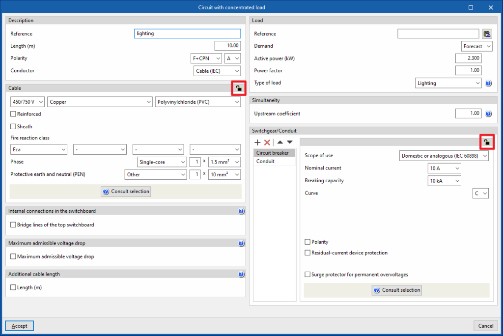
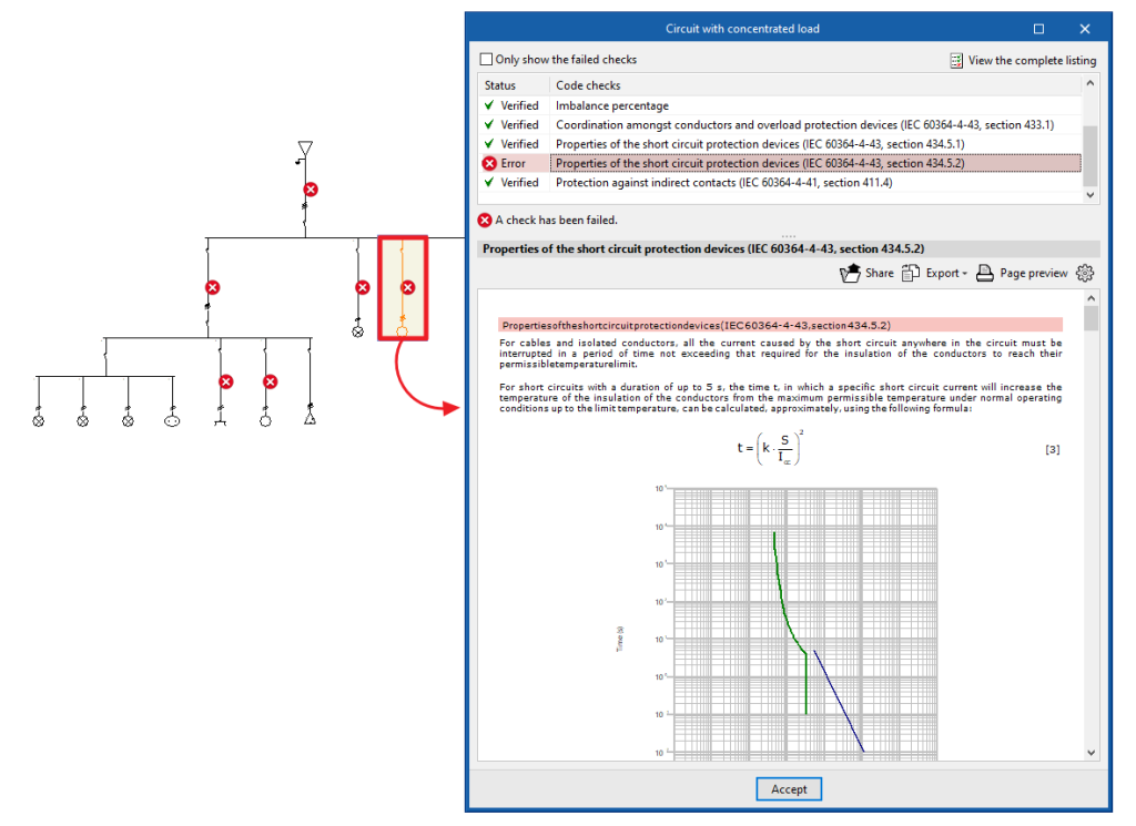
The "Concentrated load" option allows users to define and enter a concentrated load circuit. These circuits ensure that the entire load is concentrated at a point at a certain distance equal to the indicated length. Clicking on the option opens the "Circuit with concentrated load" window, which displays the following configuration options:
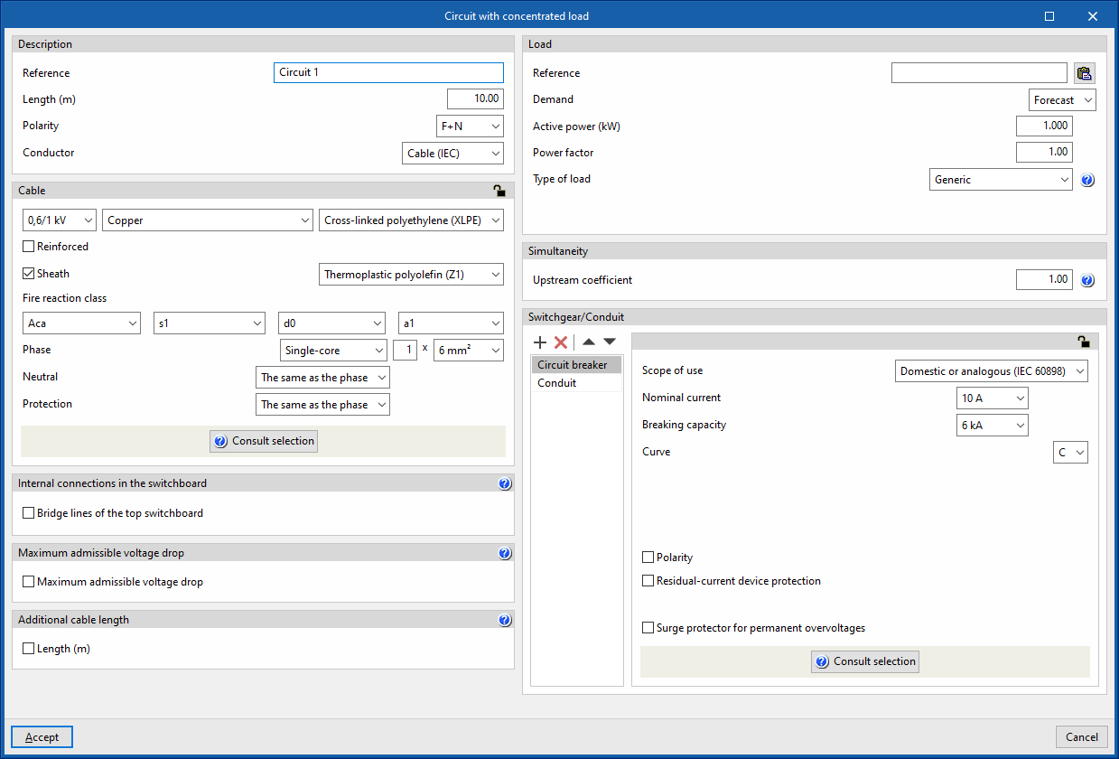
- Description
- Reference
- Length
- Polarity
- Conductor
- Cable (IEC)
- Precast conduit
- Cable (ANSI)
- Cable
- Internal connections in the switchboard
- Bridge lines of the top switchboard (optional)
By activating this option, the program allows users to enter and consider bridge lines at the top of the line. It opens the "Bridge lines of the top switchboard" window, with the following options:- Bridge lines to consider and their lengths
- Inlet (optional)
- Between switchgear (optional)
- Conductor
- Cable
- Reference installation method
- Specific reference installation method (optional)
- Bridge lines to consider and their lengths
- Bridge lines of the top switchboard (optional)
- Maximum admissible voltage drop
- Maximum admissible voltage drop (optional)
With this option, users can set a maximum admissible voltage drop value. The program will check and design the line according to the value entered.
- Maximum admissible voltage drop (optional)
- Additional cable length
With this option, users can enter a value that complements the length of the circuit for the purposes of the total cable measurement. This length can consider the connection between junction boxes and switches to complete the light points, for example, or the junctions that the circuit may include in its installation that have not been considered for the sizing of the cable, but are taken into account for its total measurement:- Length (m) (optional)
- Load
This allows the concentrated load of the circuit to be defined. This load can be entered as a forecast or by choosing one of the types of receivers defined in the element library.- Reference
A reference can be entered for the load feeding the circuit, both for cases where the demand is defined by forecast and for cases where it is defined by the receiver. In the latter case, the reference is complementary to the reference given to the electrical receiver itself.
The load reference can be typed in directly or, using the corresponding button, copied from the circuit reference, if both are to be the same. - Demand: "Forecast"
This is used when a preliminary design of the installation is being carried out in which only an expected power for the line is to be quantified. The following must be defined:- Active power (kW)
- Power factor
- Type of load
The type of load describes the nature of the element that the circuit is intended to supply. This can be as follows:- Lighting
- Emergency
- General use outlet
- Motor
The selection of this type of load implies that the connection conductors are to be sized for a current of 125 % of the full load current of the motor. - Electric vehicle charging
- Generic
- Demand: "Receiver"
In this case, users would be fully aware of the element to be placed in the installation, and choose it from the receivers library:- Type of receiver
The configuration and selection of the receiver type in the library allows the following data to be automatically displayed:- Type of load
- Power supply (Single-phase/Three-phase)
- Active power (kW)
- Type of receiver
- Reference
- Simultaneity
These options allow users to define the simultaneity of the lines. - Switchgear/Conduit
Allows the switchgear to be inserted and the conduit of the line to be defined. This can be of the following types:- Circuit breaker
- Fuse
- Magnetic starter
- Residual-current device
- Surge protector for transient overvoltages
- Sectionaliser
- Switch disconnector
- Contactor
- Network analyser
- Capacitor
- Battery
Entering switchboards
In the "Special lines" group of the main toolbar, either in the "Single-line" tab or in the "Tree" tab, there are tools for inserting frames into the program:

In the single-line diagram of the electrical installation, switchboards have a final position equivalent to that of a circuit or a set of groups, lines and circuits.
Preconfigured switchboard
Preconfigured switchboards are electrical switchboards with user-defined characteristics, which can be created and entered multiple times in the project. Editing a type of typified switchboard modifies the characteristics of all the switchboards entered associated with that type, which speeds up the work. This is useful if the installation has a large number of switchboards with the same characteristics.
Creating preconfigured switchboards
The definition of the typified tables available in the library of each job can be done through the "Project" group in the general interface toolbar, then selecting the "Element libraries" option.
The options available in the panel for creating preconfigured switchboards are as follows:
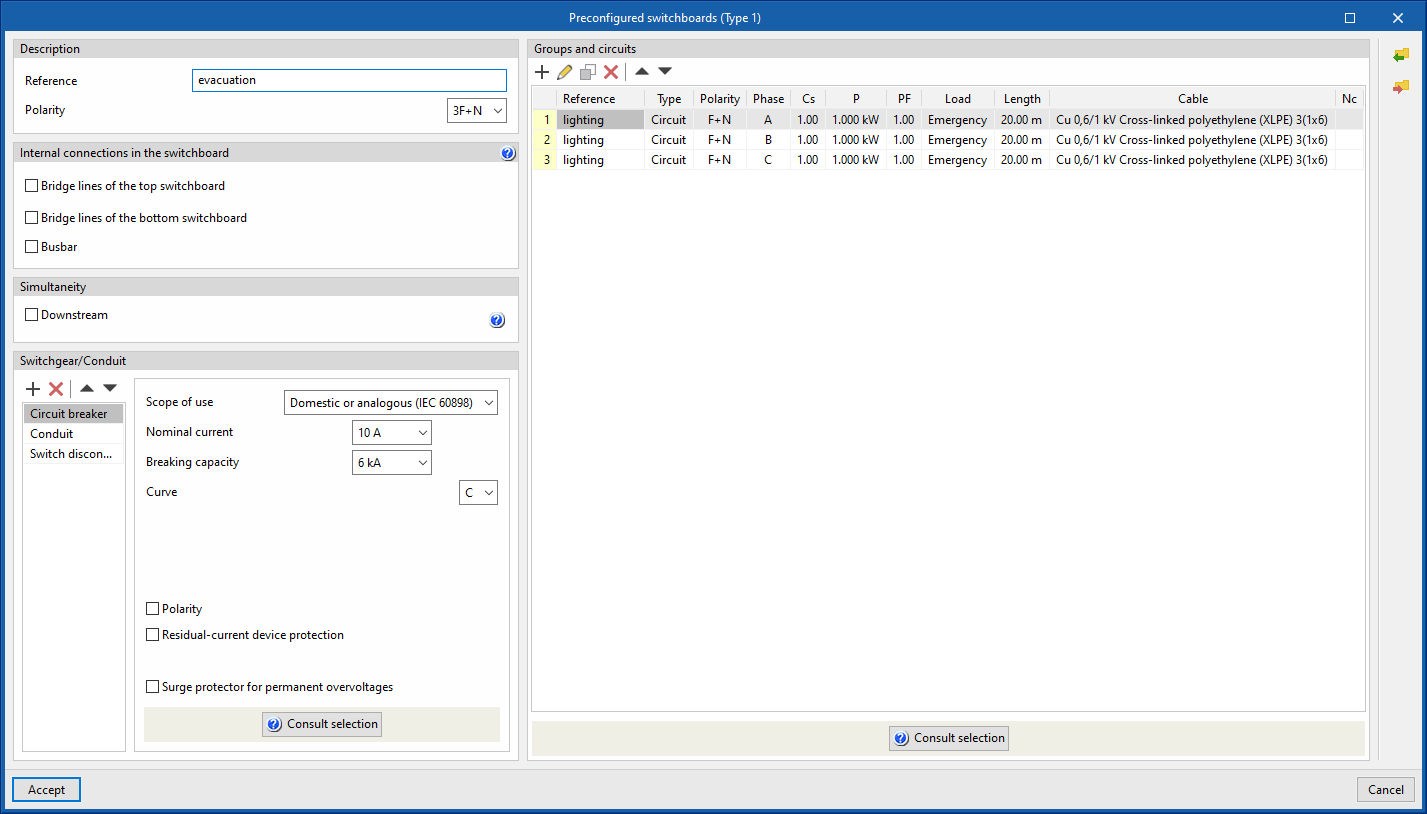
- Description
- Reference
- Polarity
- Internal connections in the switchboard
- Bridge lines of the top switchboard (optional)
By activating this option, the program allows users to enter and consider bridge lines at the top of the line. It opens the "Bridge lines of the top switchboard" window, with the following options:- Bridge lines to consider and their lengths
- Inlet (optional)
- Between switchgear (optional)
- Conductor
- Cable
- Reference installation method
- Specific reference installation method (optional)
- Bridge lines to consider and their lengths
- Bridge lines of the bottom switchboard (optional)
By activating this option, the program allows users to enter and consider bridge lines at the top of the line. It opens the "Bridge lines of the top switchboard" window, with the following options:- Bridge lines to consider and their lengths
- Inlet (optional)
- Outlet (optional)
- Conductor
- Cable
- Reference installation method
- Specific reference installation method (optional)
- Bridge lines to consider and their lengths
- Busbar
By activating this option, the program allows users to enter and consider busbars on the line.
- Bridge lines of the top switchboard (optional)
- Simultaneity
- Downstream (optional)
- Switchgear/Conduit
Allows users to enter the switchgear and define the conduits of the line. By default, this includes:- Conduit
- Groups and circuits
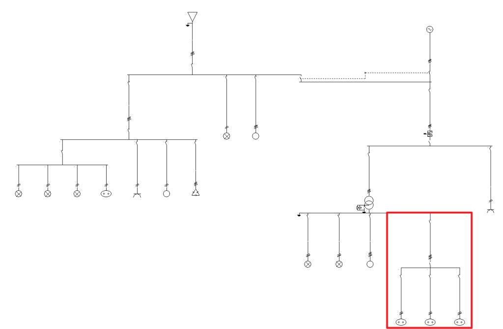
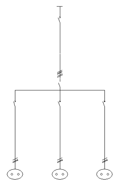
This is used to define the groups and circuits that make up the standardised table. The program displays a table in which these groups and lines can be added, edited, deleted or reordered. Clicking on "Circuit" opens the panel for editing circuits of concentrated loads and clicking on "Group" displays the corresponding panel. From "Consult selection", a partial single-line diagram of the groups and lines of the preconfigured switchboard is displayed. The following information is displayed:- Reference
- Type (Group /Circuit)
- Cs (upstream simultaneity coefficient)
- P (active power) (only in circuits)
- PF (power factor) (only in circuits)
- Load (only in circuits)
- Length (only in circuits)
- Cable (only in circuits)
- Nc (number of lines downstream) (only in groups)
Entering preconfigured switchboards
Then, to use a preconfigured switchboard, select the "Preconfigured switchboard" option in the "Special lines" group of the general interface toolbar.
The following parameters can be defined in the input window of the standard table:
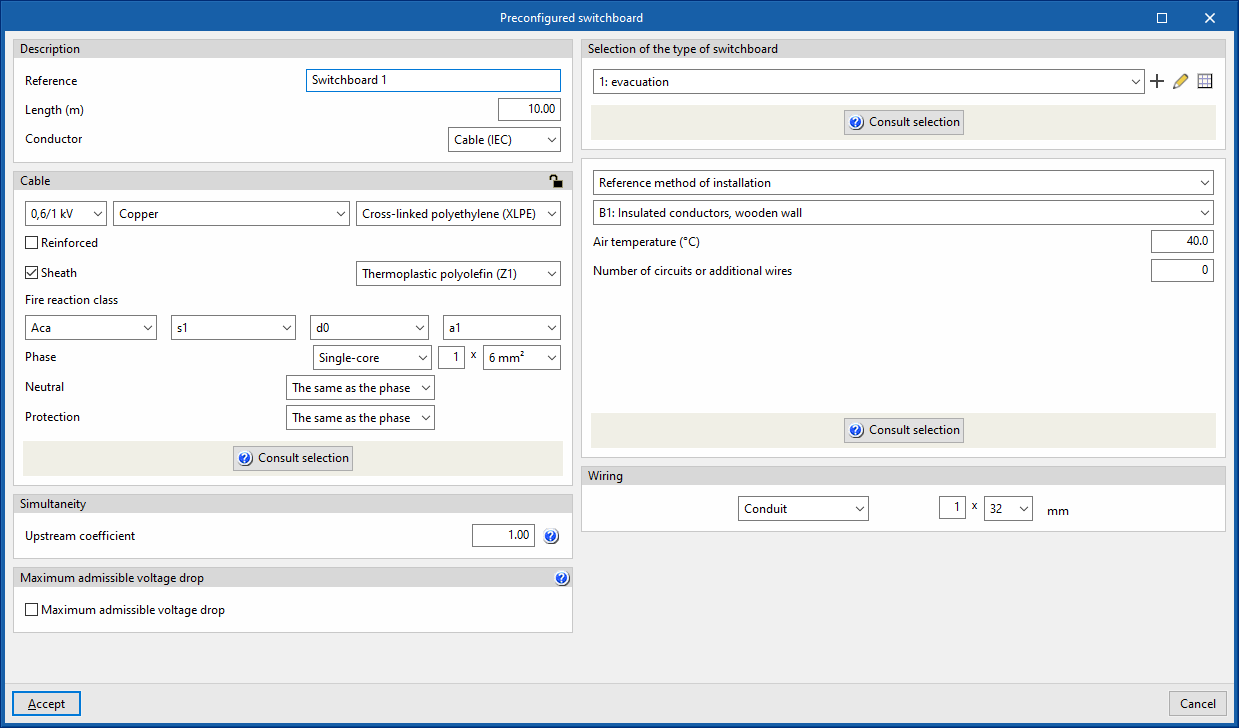
- Description
- Reference
- Length (m)
- Conductor
- Cable (IEC)
- Precast conduit
- Cable (ANSI)
- Cable
- Simultaneity
- Upstream coefficient
- Maximum admissible voltage drop
- Maximum admissible voltage drop (optional)
Con esta opción es posible fijar un valor de caída de tensión With this option, users can set a maximum admissible voltage drop value. The program will check and design the line according to the value entered.
- Maximum admissible voltage drop (optional)
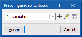
- Selection of the type of switchboard
Allows users to select a preconfigured switchboard created in the element libraries or to create it directly. - Conduit
Allows users to define the conduit of the line.
Anticipated pane
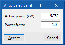
This allows users to represent a power supply line to a switchboard or sub-switchboard with a simplified load forecast, without the need to detail the internal groups and circuits. This line functions as a final line.
Clicking on the option opens the "Anticipated panel" window, which displays the following configuration options:

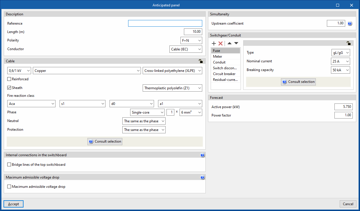
- Description
- Reference
- Length (m)
- Polarity
- Conductor
- Cable
- Internal connections in the switchboard
- Bridge lines of the top switchboard (optional)
By activating this option, the program allows users to enter and consider bridge lines at the top of the line. It opens the "Bridge lines of the top switchboard" window, with the following options:- Bridge lines to consider and their lengths
- Inlet (optional)
- Between switchgear (optional)
- Conductor
- Cable
- Reference installation method
- Specific reference installation method (optional)
- Bridge lines to consider and their lengths
- Bridge lines of the top switchboard (optional)
- Maximum admissible voltage drop
- Maximum admissible voltage drop (optional)
With this option, users can set a maximum admissible voltage drop value. The program will check and design the line according to the value entered.
- Maximum admissible voltage drop (optional)
- Simultaneity
- Upstream coefficient
- Switchgear/Conduit
Allows the switchgear to be entered and the line conduit to be defined. By default, it includes the following:- Fuse
- Meter
- Conduit
- Switch disconnector
- Circuit breaker
- Residual-current device
- Forecast
Allows users to define the power forecast of the switchboard by giving the following data:- Active power (kW)
- Power factor
Replacing lines with switchboards
The program has several options that allow users to replace lines previously entered in the diagram with preconfigured switchboards or tables by forecast:
Replace line with preconfigured switchboard
Allows users to select a line in the diagram and replace it with a preconfigured switchboard defined in the element library.
Entering special lines
In the "Special lines" group of the main toolbar, either in the "Single-line" tab or in the "Tree" tab, the following elements can be defined and entered:

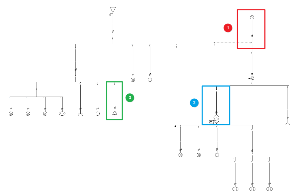
The program offers great versatility when it comes to placing special lines in the single-line diagram of the electrical installation:
- Complementary supply (1)
- LV/LV transformer (2)
- Capacitor bank (3)
Complementary supply
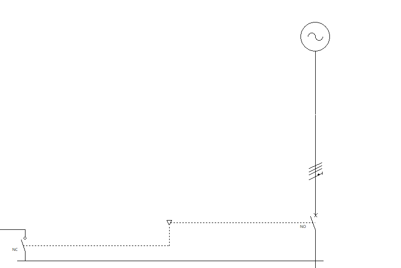
This option allows users to add an additional complementary supply corresponding to a generator set, in addition to the ordinary supply defined in the "Supply" option of the "Project" group.
The complementary supply through a generator set can provide service to the whole installation, to part of the installation or to start up the emergency services deemed appropriate in the event of failure of the normal supply.
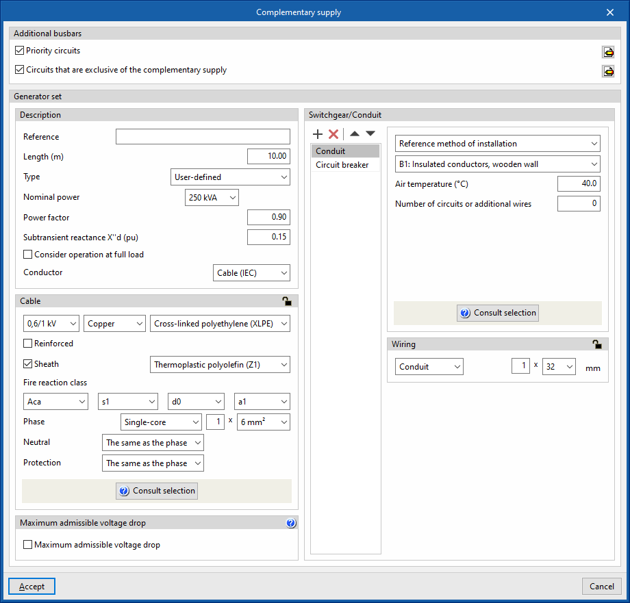
Clicking on the option opens the "Complementary supply" window, which allows the following parameters to be configured:
- Additional busbars
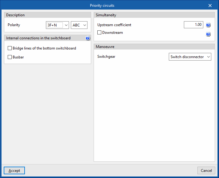
In this section, users can specify the existence of priority circuits or circuits that are exclusive of the complementary supply:- Priority circuits (optional)
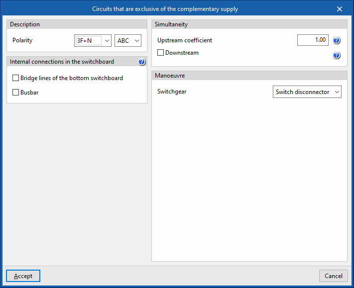
Allows users to define priority circuits that are fed by both the ordinary supply and the complementary supply. - Circuits that are exclusive of the complementary supply (optional)
Allows users to define priority circuits that are fed by both the ordinary supply and the complementary supply.
Both options can be activated, thus having both priority circuits and exclusive circuits. The rest of the circuits, neither priority nor exclusive, will be powered only by the ordinary supply.
When activating any of these options, the program displays a window in which these circuits are configured, including the following data:- Description
- Polarity
- Internal connections in the switchboard
- Bridge lines of the bottom switchboard
- Busbar
- Simultaneity
- Manoeuvre
- Switchgear (Switch disconnector / Circuit breaker / Contactor)
- Description
- Priority circuits (optional)
- Generator set
In this section, users will find the details of the generator set, as well as the cable, switchgear and conduit of the line corresponding to the complementary supply:- Description
- Reference
- Length
- Type:
- User defined
- Nominal capacity
- Power factor
- Subtransient reactance X''d (pu)
- Manufacturer generator set
- User defined
- Consider operation at full load (optional)
- Conductor
- Cable (IEC)
- Precast conduit
- Cable (ANSI)
- Cable
- Switchgear/Conduit
By default, this includes:- Conduit
- Circuit breaker
- Description
LV/LV transformer
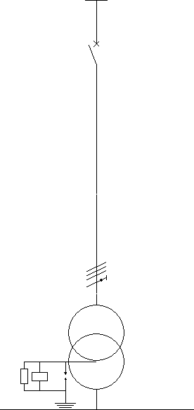
This option allows users to add an intermediate low-voltage-low-voltage transformer along the length of the installation.
This allows the nominal voltage to be raised or lowered, as is the case with the use of a transformer for installations supplied at very low safety voltage (MBTS).
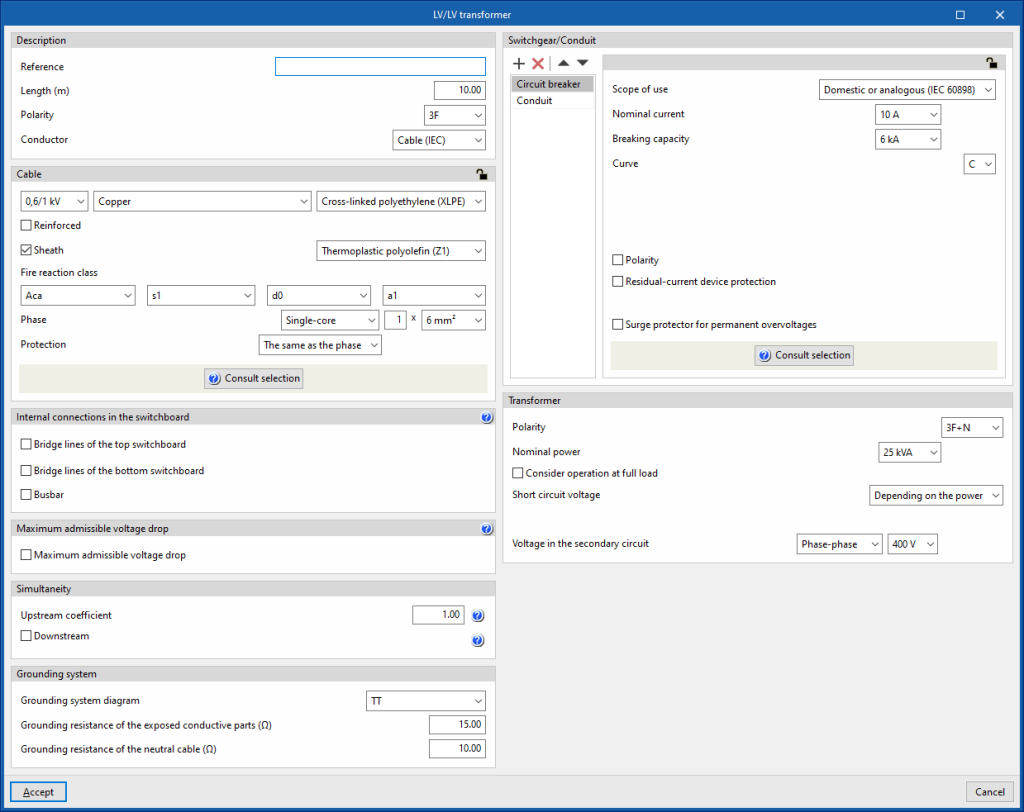
Clicking on this option opens the "LV/LV transformer" window, which allows the following parameters to be configured:
- Description
- Reference
- Length
- Polarity
- Conductor
- Cable (IEC)
- Precast conduit
- Cable (ANSI)
- Cable
- Internal connections in the switchboard
- Bridge lines of the top switchboard (optional)
- Bridge lines of the bottom switchboard
- Busbar (optional)
- Maximum admissible voltage drop
- Maximum admissible voltage drop (optional)
- Simultaneity
- Switchgear/Conduit
By default, this includes:- Circuit breaker
- Conduit
- Transformer
This section provides details of the transformer data as well as the secondary winding voltage:- Polarity
- Nominal power (kVA)
- Consider operation at full load (optional)
With this option, the calculation current of the transformer line is obtained from its rated power, instead of taking the power of the loads it feeds. - Short circuit voltage (Depending on the power / User defined (%, kW))
- Voltage in the secondary circuit (Phase-neutral / Phase-phase) (V)
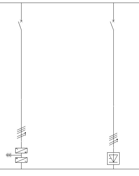
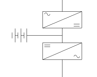
UPS (Uninterruptible power supply)
This option allows a UPS ( Uninterruptible power supply) to be added to the installation. These systems guarantee the power supply in the event of mains power failure through the use of batteries.
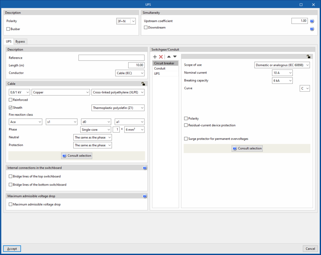
Clicking on it opens the "UPS" window, which allows the following parameters to be configured:
- Description
- Polarity
- Busbar
- Simultaneity
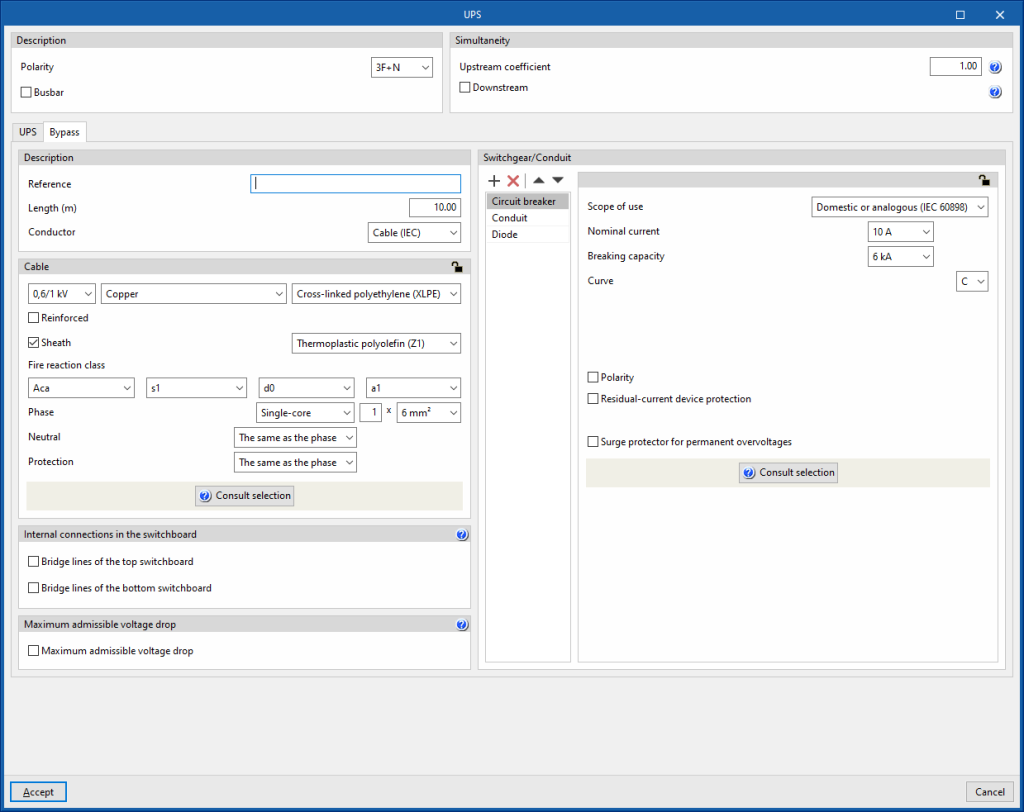
The UPS group consists of two lines, which are detailed in the editing window through two tabs, "UPS" and "Bypass":
- "UPS" tab
This corresponds to the main line. It contains the rectifier, the batteries and the inverter. - “Bypass” tab
Corresponds to the bypass line and allows normal battery-free operation.
Each of the lines operates as an independent element, with its own protection elements, analyses and the corresponding checks for correct operation. The following configuration options appear in each one of them:
- Description
- Reference
- Length
- Conductor
- Cable
- Internal connections in the switchboard
- Bridge lines of the top switchboard (optional)
- Bridge lines of the bottom switchboard (optional)
- Maximum admissible voltage drop
- Maximum admissible voltage drop (optional)
- Switchgear/Conduit
By default, this includes:- Circuit breaker
- Conduit
- UPS (in the main line)
- Power
- Power factor
- Short circuit contribution factor
- THDI3
- Diode (in the bypass line)
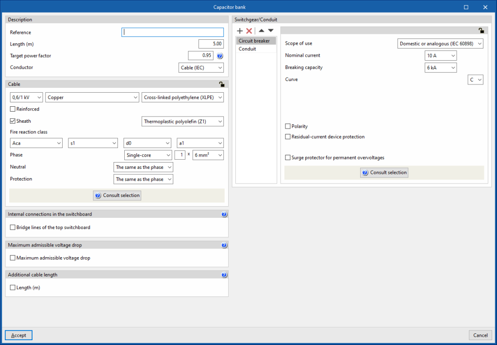
Capacitor bank
This option allows a capacitor bank to be added to the installation. The capacitor bank can be installed to improve the power factor of a group of circuits collectively. This is useful in installations where the resulting power factor is less than 1.
Clicking on it opens the "Capacitor bank" window, which allows the following parameters to be configured:
- Description
- Reference
- Length (m)
- Target power factor
- Conductor
- Cable
- Internal connections in the switchboard
- Bridge lines of the top switchboard (optional)
- Maximum admissible voltage drop
- Maximum admissible voltage drop (optional)
- Additional cable length
With this option, users can enter a value that supplements the circuit length for the total cable measurement. This is not taken into account for the design:- Length (m)
- Switchgear/Conduit
By default, this includes:- Circuit breaker
- Conduit
Defining cables in lines and circuits
Cables can be defined in the "Cable" section, located on the left-hand side of the editing panels for lines, circuits, panels and special lines.
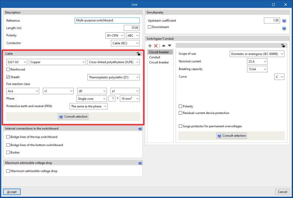
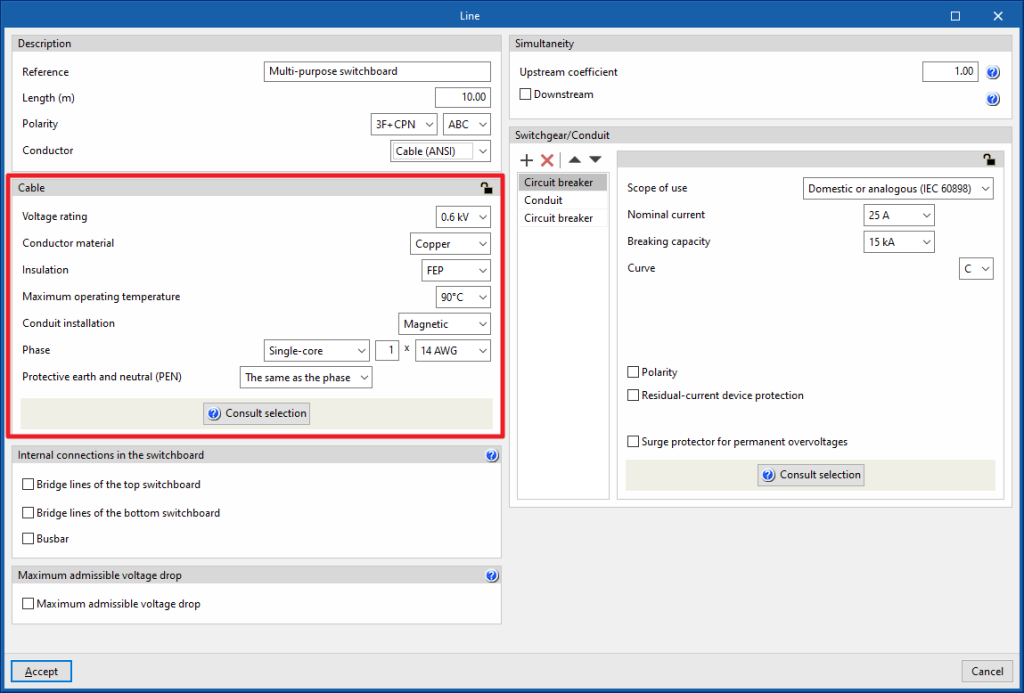
The definition options available in this section vary depending on whether a "Cable (IEC)" or "Cable (ANSI)" is defined in the "Conductor" option in the "Description" section of the line, circuit, switchboard or special line. They are as follows:
Defining IEC cables
If an IEC standard cable is defined, the program allows the following parameters to be configured:
- Nominal voltage (0,6/1 kV / 450/750 V / 300/500 V)
- Material (Copper/Aluminium)
- Insulation
- Reinforcement (optional)
- Selecting the reinforcement material
- Roof (optional)
- Selecting the reinforcement material
- Fire reaction class
- Phase
- Single-core / Multi-conductor
- Number of conductors per pole x Section of the conductor
- Neutral
This can be "The same as the phase" or "Other":- Single-core / Multi-conductor
- Number of conductors per pole x Section of the conductor
- Protection
This can be "The same as the phase", "Without conductor" ( if there is no need for the protective conductor distribution) or "Other":- Single-core / Multi-conductor
- Number of conductors per pole x Section of the conductor
- Protective earth and neutral (PEN)
Only available in polarity 3F + CPN, 2F + CPN or F + CPN. This can be "The same as the phase", "Without conductor" or "Other":- Single-core / Multi-conductor
- Number of conductors per pole x Section of the conductor
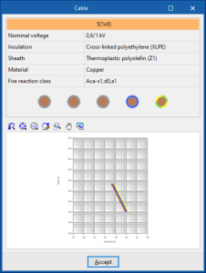
By clicking on the "Consult selection" option, a panel is displayed which provides clarification about the data entered, as well as a current-time graph of the thermal resistance of the cable.
Defining ANSI cables
If a cable is defined under the ANSI standard, the program allows the following parameters to be configured:
- Voltage rating (0,6/1 kV / 450/750 V / 300/500 V)
- Conductor material (Copper / Aluminium)
- Insulation
- Maximum operating temperature
- Conduit installation (Magnetic / Not magnetic)
- Phase
- Single-core / Multi-conductor
- Number of conductors per pole x Section of the conductor
- Neutral
This can be "The same as the phase" or "Other":- Single-core / Multi-conductor
- Number of conductors per pole x Section of the conductor
- Protection
This can be "The same as the phase", "Without conductor" ( if there is no need for the protective conductor distribution) or "Other":- Single-core / Multi-conductor
- Number of conductors per pole x Section of the conduct
- Protective earth and neutral (PEN)
Only available in polarity 3F + CPN, 2F + CPN or F + CPN. This can be "The same as the phase", "Without conductor" or "Other":- Single-core / Multi-conductor
- Number of conductors per pole x Section of the conductor
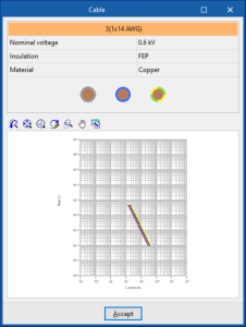
By clicking on the "Consult selection" option, a panel is displayed which provides clarification about the data entered, as well as a current-time graph of the thermal resistance of the cable.
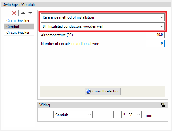
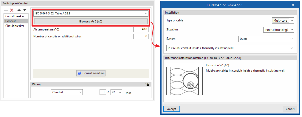
The panel for defining the type of conduit and the installation method is also adapted to the cable selection made.
The program incorporates the grouping correction factor tables for all installation methods in accordance with IEC 60364-5-52. Some tables for certain installation methods may not provide a grouping correction factor for a large number of conductors, in which case the program uses the most unfavourable factor from the table and indicates this with a warning message in the ampacity test. This extension can be used for cables with more than 2500 A for transformer outgoing current, for example.
Defining prefabricated conduits
EPrefabricated conduits can be defined and used as conduits for the installation.
Creating prefabricated conduit types
The definition of the prefabricated ducts available in each job can be done through the "Project" group in the toolbar of the general interface, then selecting the "Element libraries" option.
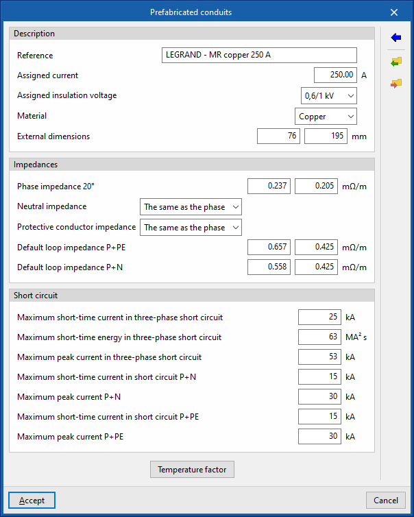
The options available in the panel for creating prefabricated conduit types are as follows:
- Description
- Reference
- Assigned current (A)
- Assigned insulation voltage (kV)
- Material (Copper / Material)
- External dimensions (mm)
- Impedances
- Phase impedance 20ºC (mΩ/m)
- Neutral impedance (The same as the phase / Other (mΩ/m))
- Protective conductor impedance (The same as the phase / Other (mΩ/m))
- Default loop impedance P + PE (mΩ/m)
- Default loop impedance P + N (mΩ/m)
- Short circuit
- Maximum short-time current in three-phase short circuit (kA)
- Maximum short-time energy in three-phase short circuit (MA2 s)
- Maximum peak current in three-phase short circuit (kA)
- Maximum short-time current in short circuit P + N (kA)
- Maximum peak current P + N (kA)
- Maximum short-time current in short circuit P + PE (kA)
- Maximum peak current P + PE (kA)
- Temperature factor
Allows users to access a table in which a value of the factor is applied for each temperature value:- Temperature (ºC)
- Factor
The program allows users to import predefined types of prefabricated conduits using the options on the right-hand side.
Using prefabricated conduits in lines or circuits
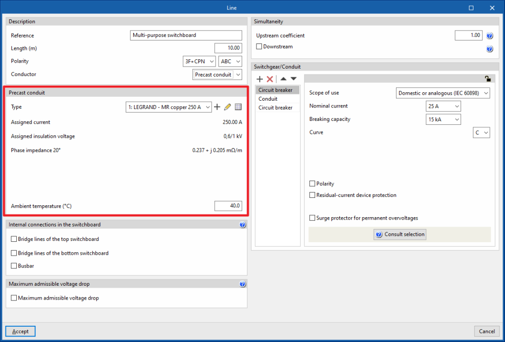
Then, in order to use a busbar trunking conduits for lines, circuits, switchboards or special lines, the "Busbar" option must be selected in the "Conductor" section under the "Description" section when entering or editing the "Precast conduit" option.
Selecting the "Type" of prefabricated conduit provides a direct display of the most representative parameters of the selection made. This makes it easier to find out the properties of the selected library element:
- Assigned current
- Assigned insulation voltage
- Phase impedance 20ºC
Furthermore, the program needs the following parameter to be defined:
- Ambient temperature (ºC)
Defining bridge lines
In high-power installations, users must correctly design the internal connections in the control and protection panel (busbars and bridge lines).
All switchgear elements that are located between the raceways of two consecutive levels shall be included in the same switchboard.
Bridge lines are the lines used to connect devices located in the same switchboard.
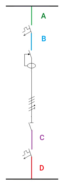
Two groups of bridge lines will be distinguished according to their location in the conduit: bridge lines at the top (which establish an interconnection between the elements located upstream of the conduit) and bridge lines at the bottom (which connect the devices located downstream of the conduit).
Bridge lines of the top switchboard
- Inlet (A)
They represent the sections of cable that supply the switchgear input of the line. Activating this option only makes sense when the input bridges of the lines start from a busbar located in the line immediately above. In this case, the busbar would act as a current distributor, causing the sections of the bridges (S1) to be reduced compared to the output bridge of the line above (S2).
- Between switchgear (B)
They represent the cable sections that connect elements of the same line arranged in series. Activating this option only makes sense if there are at least two devices for the same line in the same box.
Bridge lines of the bottom switchboard
- Between switchgear (C)
They represent the cable sections that connect elements of the same line arranged in series. Activating this option only makes sense if there are at least two devices for the same line in the same box.
- Outlet (D)
They represent the cable sections that connect the switchgear arranged at the output of the line with the elements that are located downstream of it (busbars, protection devices, manoeuvring elements, etc.).
Entering bridge lines
Bridge lines are entered in the program in the "Internal connections in the switchboard" section using the editing panel for groups, lines, circuits, switchboards, special lines and supplies. From here, users can activate the following checkboxes, which are available depending on the element being edited:
- Bridge lines of the top switchboard
- Bridge lines of the bottom switchboard
- Bridge lines (only in groups)
For greater clarity on the concept of bridge lines, this section includes an aid that details the different bridge lines that may be present in the switchboards that make up the electrical installation.
Use examples
In a diagram with a parent line and several child lines, the following options can be activated to define the bridge lines between the protections arranged in them:
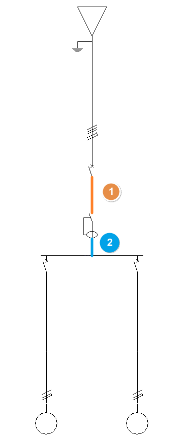
- Bridge lines with no busbar
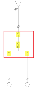
In a diagram without a busbar, simply edit the parent line and activate the two boxes "Between switchgear" (1), which represents the section between the protections of the parent line, and "Outlet" (2), which represents the section between the last protection of the parent line and the first protection of the child line, in its editing panel.
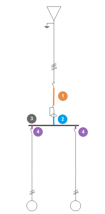
- Bridge lines with busbar
In a diagram with a busbar, both parent and child lines must be edited:- On the parent line, three boxes are activated: "Between switchgear" (1), which represents the section between its protections, "Outlet" (2), which represents the section between the last protection and the busbar, and "Busbar" (3).
- On each of the child lines, the "Inlet" box (4) is activated, which represents the section between the busbar and the first protection of the child line.
Reference installation method for bridge lines
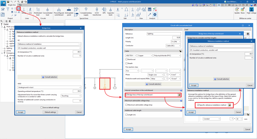
In order to simplify the selection of the installation method on bridge lines, the "Bridge lines" option is available in the "Project" group of the general interface, where the default reference installation method to be considered for all bridge lines is selected.
If necessary, the reference installation method for the bridge lines of the switchgear to which they belong can be edited individually at a later date and in detail. To do this, access the bridge line via the "Internal connections in the switchboard" section of the element's editing panel and activate the "Specific reference installation method" option.
Checking bridge lines
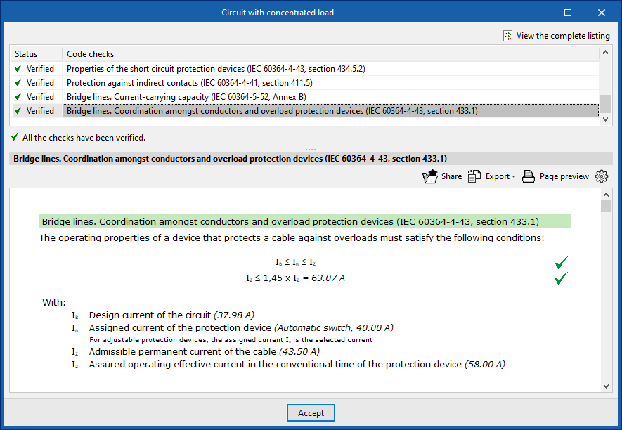
Checks are carried out on the ampacity and coordination between conductors and the overload protection devices on the bridging lines so that the maximum admissible current of the cable forming the bridge line is above the rated current of the protection device protecting it.
Designing bridge lines
When designing the electrical installation, it is also possible to design the overload bridge lines (heating).
Furthermore, the bridge lines that have not been activated manually in each of the lines belonging to the electrical installation can be generated automatically with the "Generate bridge lines" option. Checking this option enables the design of the installation's bridge lines depending on the busbar layout (in which case the inlet lines to the protection devices will be activated) and the series connection of the switchgear (in which case the bridge lines between switchgear will be activated).
The default cable type and lengths assigned for the automatically generated bride lines are set in the "Design options" of the "Project" group.
Defining busbars
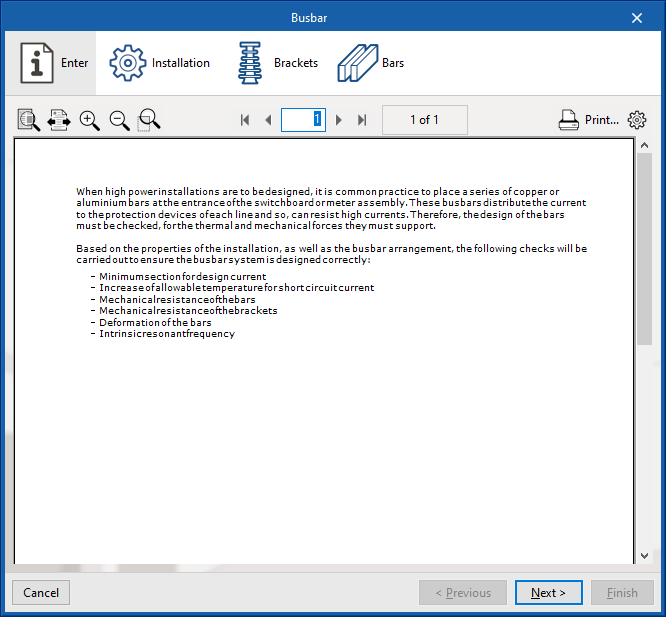
When high-power installations are planned, a series of copper or aluminium bars are usually placed at the inlet of the general control and protection panel or in the distribution of meters. These busbars are used to distribute the current to the protection of each line, which means that they withstand very high currents. It is therefore necessary to check the correct design of the bars, both for the thermal forces and for the mechanical forces that they will have to withstand.
Based on the properties of the installation as well as the busbar layout, the following checks are carried out:
- Minimum section for design current
- Increase of allowable temperature for short circuit current
- Mechanical resistance of the bars
- Mechanical resistance of the brackets
- Deformation of the bars
- Intrinsic resonant frequency
To use a busbar on the lines, in the "Internal connections in the switchboard" section of the entry or editing panel, the "Busbar" option must be selected.
This can be used to access a busbar entry assistant, which has four tabs: "Enter", "Installation", "Brackets" and "Bars":
“Enter” tab
This tab details the common use of busbars and the checks carried out on them in the program.
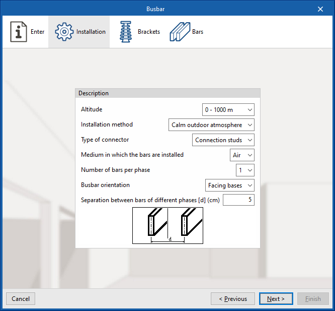
“Installation” tab
Allows users to describe the general parameters of the busbar installation:
- Description
- Altitude
- Installation method
- Type of connector
- Medium in which the bars are installed
- Number of bars per phase
- Busbar orientation
- Separation between bars of different phases [d] (cm)
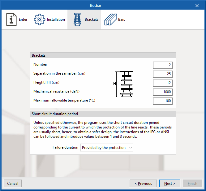
“Brackets” tab
The number, geometry and properties of the busbar brackets as well as the short-circuit duration time can be set:
- Brackets
- Number
- Separation in the same bar (cm)
- Height [H] (cm)
- Mechanical resistance (daN)
- Maximum allowable temperature (ºC)
- Short circuit duration period
Unless specified otherwise, the program uses the short circuit duration period corresponding to the current to which the protection of the line reacts. These periods are usually short, hence, to obtain a safer design, the instructions of the IEC or ANSI can be followed and introduce values between 1 and 3 seconds.- Failure duration (User defined (sec) / Provided by the protection)
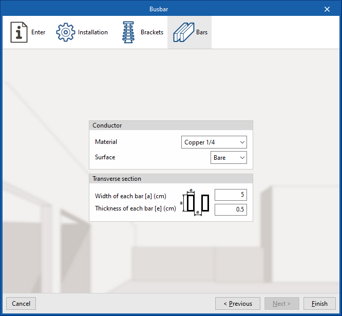
“Bars” tab
Allows the material, surface and section of the busbars to be adjusted:
- Conductor
- Material
- Surface (Bare / Painted)
- Transverse section
- Width of each bar [a] (cm)
- Thickness of each bar [a] (cm)
Defining the types of receiver
The types of receivers available in each job can be defined via the "Project" section of the general interface toolbar, then selecting the "Element libraries" option.
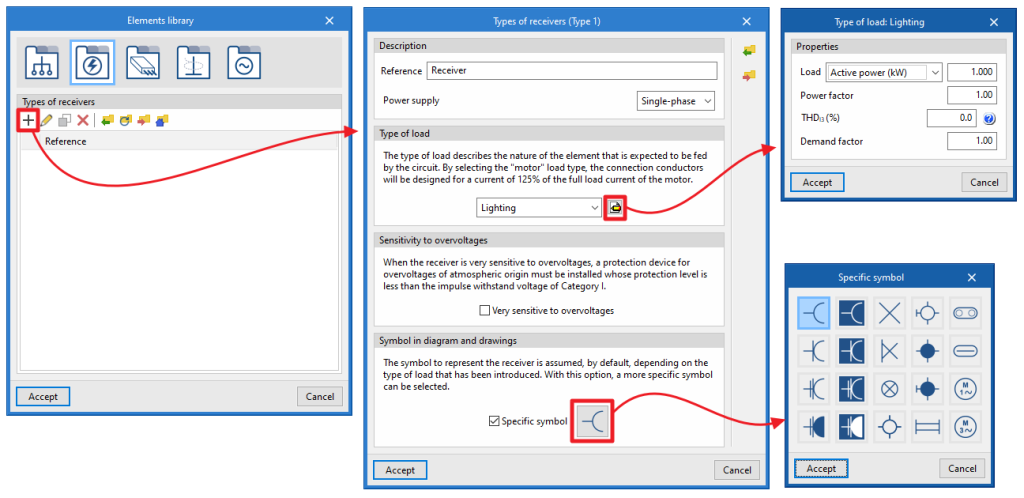
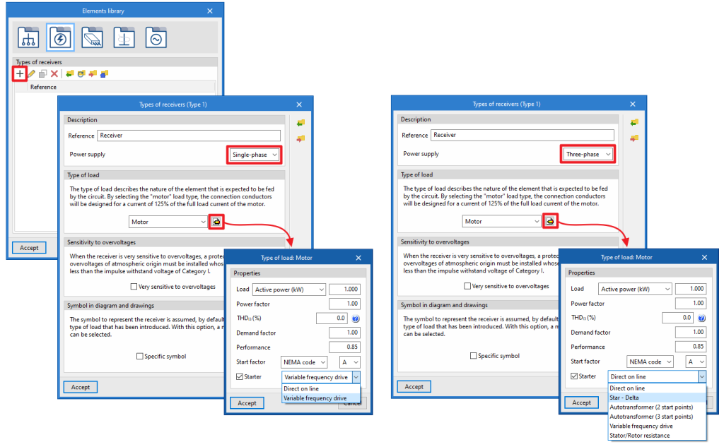
When an element is added to the table, the "Types of receivers" window opens, in which the following parameters are configured:
- Description
- Reference
- Power supply (Single -phase / Three-phase)
- Type of load
The load type describes the nature of the element that the circuit is intended to supply.- Selecting the type of load
- Lighting
- Emergency
- General use outlet
- Motor
- Electric vehicle charging
- Generic
- Defining the characteristics of the type of load
- Load (Apparent power (kVA) / Active power (kW) / Rated current
- Power factor
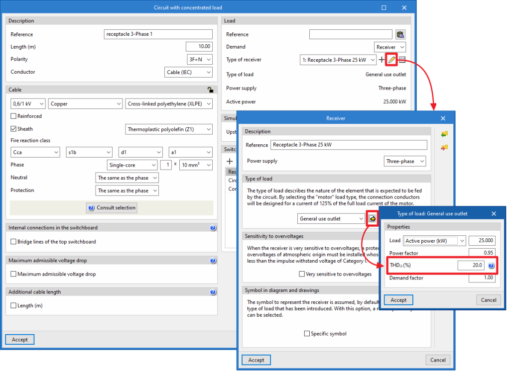
- THDI3 (%) (range 3 harmonic distortion index)
Allows users to enter the percentage of the third harmonic distortion present in the load. - Demand factor
- Performance (only in motors)
- Start factor (only in motors)
- NEMA code / Generic
- Starter (optional; only in motors)
- Direct / Variable frequency drive
- Selecting the type of load
- Sensitivity to overvoltages
This is used to indicate that the receiver is very sensitive to overvoltages. In this case, an atmospheric overvoltage protection device with a protection level lower than the Category I impulse withstand voltage must be installed.- Very sensitive to overvoltages (optional)
- Symbol in diagram and drawings
The symbol for representing the receiver is assumed, by default, depending on the type of load entered. The selected symbol will represent the electrical receiver in the single-line diagram of its own power supply circuit.- Specific symbol (optional)
Allows users to select a specific symbol from a small library of symbols integrated in the program.
- Specific symbol (optional)
Managing the simultaneity of loads
Load simultaneity is managed in the "Simultaneity" section, and can be accessed from the editing panel for groups, lines, circuits, switchboards and special lines.
These options allow users to define both upstream and downstream simultaneity:
- Upstream coefficient
The simultaneity coefficient indicates what fraction of the load is to be considered upstream of the line. - Downstream (optional)
If this option is not activated, the line load is equal to the direct accumulation of the downstream loads without any reduction. If activated, the program allows users to select between the following simultaneity options:- Factor
The line load is equal to the downstream load accumulation multiplied by this simultaneity factor. - Intensity (A)
Allows users to define a current value that completely replaces the calculated current corresponding to the downstream lines. It therefore acts as if it were a disconnection of the network at that point of the installation with respect to the downstream lines. - Power (kW)
This allows users to define a power value that completely replaces the calculated power corresponding to the downstream lines. Therefore, it also acts as if it were a disconnection from the network at that point of the installation with respect to the downstream lines.
- Factor
Defining switchgear and conduits in lines and circuits
Switchgear and conduits can be defined in the "Switchgear/Conduit" section, located on the right-hand side of the editing panels for groups, lines, circuits, switchboards and special lines.
A table can be used to insert, delete or reposition different types of switchgear at the head or foot of each line.
The switchgear available in the program and the conduit definition options are as follows:
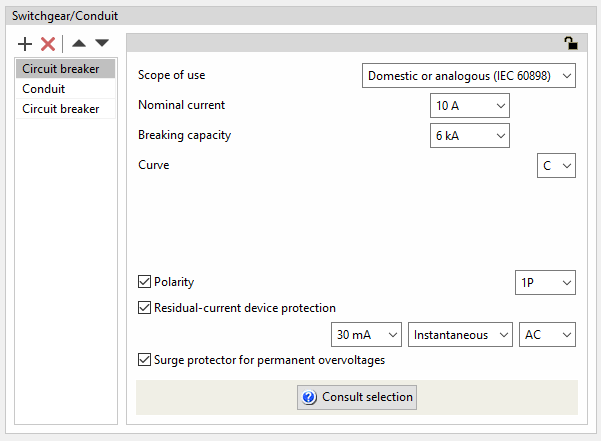
Circuit breaker
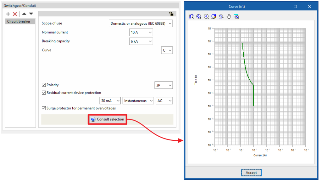
Circuit breaker protection is an element normally used to protect the line against overcurrents and short circuits. It is also possible to associate differential protection against indirect contact with the circuit breaker. The program allows circuit breakers to be added to groups, lines and domestic or analogue, tertiary or industrial circuits, indicating the following characteristics:
- Scope of use: Domestic or analogous (IEC 60898)
- Nominal current (A)
- Breaking capacity (kA)
- Curve
- Polarity (optional)
- Residual-current device protection (optional)
- Sensitivity
- Type
- Class
- Surge protector for permanent overvoltages (optional)
The nominal current of the residual-current device protection will be the same as the one defined in the circuit-breaker properties.
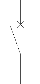
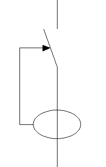
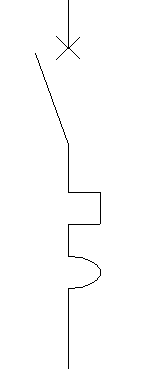
If the "Surge protector for permanent overvoltages" checkbox is activated, an icon will appear on the single-line diagram representing the coil system that is usually installed in circuit breakers to trigger them in the event of a fluctuation that increases the voltage value above the safety limit.
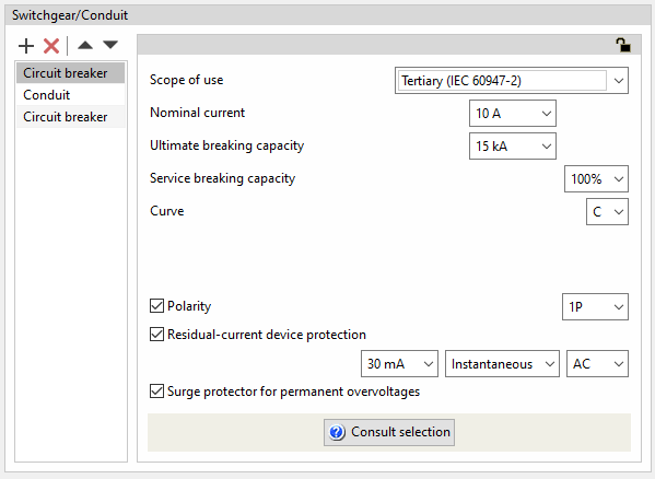
- Scope of use: Tertiary (IEC 60947-2)
- Nominal current (A)
- Breaking capacity (kA)
- Service breaking capacity (25% / 50% / 75% / 100%)
- Curve (B / C / D)
- Polarity (optional)
- Residual-current device protection (optional)
- Sensitivity
- Type
- Class
- Surge protector for permanent overvoltages (optional)
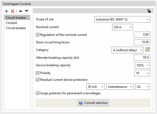
- Scope of use: Industrial (IEC 60947-2)
- Nominal current (A)
- Regulation of the nominal current (optional)
As well as setting the nominal current of the device, this value can be regulated by entering the regulation value in the switchboard.- Regulation factor of the rated current
- Short circuit firing factor
The short circuit firing factor shall define the position of the vertical part of the firing curve of the device as a result of multiplying the value of the regulated current by the short circuit firing factor. - Category
The device category is used to define the last step of the intensity/time graph.- A (without delay)
- B (with delay)
- Short delay period (s)
- Short-time current-carrying capacity (kA)
- Ultimate breaking capacity (kA)
- Service breaking capacity
It is set as quartiles of the ultimate breaking capacity:- 25% / 50% / 75% / 100%
- Curve (B / C / D)
- Polarity (opcional)
- Residual-current device protection (optional)
- Sensitivity
- Type (Instantaneous / Selective)
- Clase (AC / A / A 'Si' / B / B 'Si')
- Surge protector for permanent overvoltages (optional)
By clicking on the "Check selection" option, the intensity-time curve corresponding to the characteristics entered is displayed.
Residual-current device
Residual-current device protection is used to protect a line against indirect contacts and leakage current losses. The program can be used to define residual-current device protection in a group, line or circuit with the following characteristics:
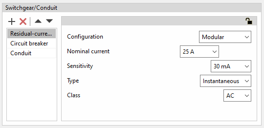
Modular residual-current device
- Configuration: Modular
- Nominal intensity (A)
- Sensitivity
- Type (Instantaneous / Selective)
- Class
- AC
- A
- A 'Si' (super-immunised)
- B
- B 'Si' (super-immunised)
- AC / A / A 'Si' / B / B 'Si')
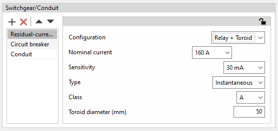
Residual current relays with toroids
To extend the selection of residual-current device protection with a higher nominal current, the program has the option to select residual-current device protection by means of a toroidal device linked to its corresponding trip relay.
- Configuration: Relay + Toroid
- Nominal intensity (A)
- Sensitivity
- Type (Instantaneous / Selective)
- Class
- AC
- A
- A 'Si' (super-immunised)
- B
- B 'Si' (super-immunised)
- Toroid diameter (mm)
This is the diameter required to cover the cables to be protected.
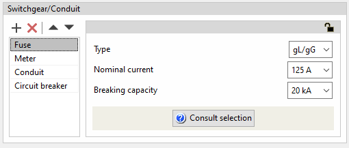
Fuse
Like the circuit breaker, fuses are generally used to protect the line against overcurrents and short circuits.
The program can be used to define fuses in a group, line or circuit by indicating the following characteristics:
- Type (gL/gG / aM)
- Nominal current (A)
- Breaking capacity (kA)
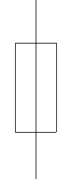
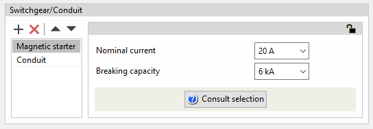
Magnetic starter
The magnetic starter is the element that is usually fitted for overcurrent and short-circuit protection on lines feeding motor loads.
The program can be used to define magnetic starters in a line or a circuit by specifying the following characteristics:
- Nominal current (A)
- Breaking capacity (kA)
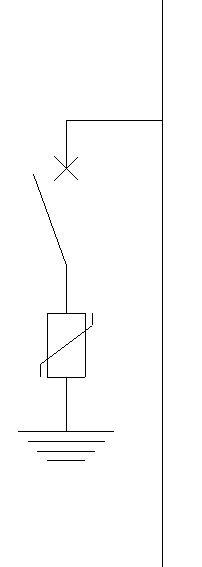
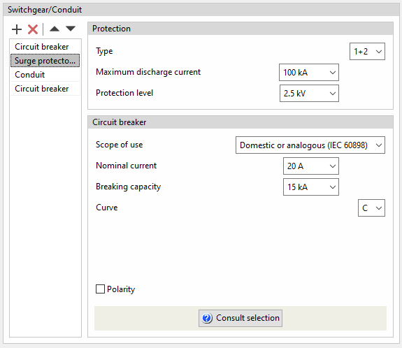
Surge protector for transient overvoltages
The program can be used to define surge protector for transient overvoltages (protection device for overvoltages of atmospheric origin) in a group, a line or a circuit by specifying the following characteristics:
- Protection
- Type (1+2 / 1 / 2 / 3)
- Maximum discharge current (kA)
- Protection level (kV)
- Circuit breaker
Used to define the circuit breaker associated with the transient overvoltage limiter, with the same options as when entering it independently.
Sectionaliser
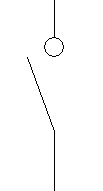
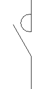
This option is used to add a disconnector at the group, line or circuit level. The program does not require any additional parameter definition.
Switch disconnector
This option is used to add a switch disconnector to the line or circuit. The program does not require any additional parameter definition.
Contactor
This option is used to add a contactor to the group, line or circuit. The program does not require any additional parameters to be defined.
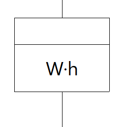
Meter
This option is used to add a meter to the line. The program does not require any additional parameter definition.
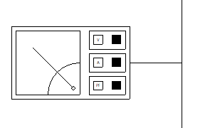
Network analyser
This option is used to add a network analyser to the group, line or circuit. The program does not require any additional parameters to be defined.
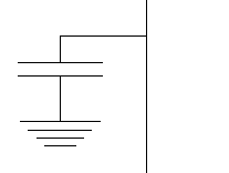
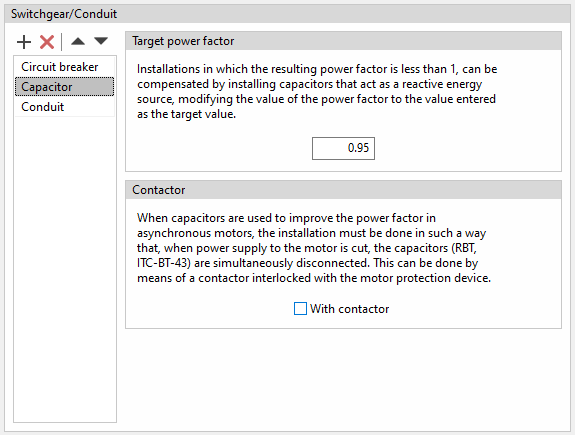
Capacitor
This option is used to add a capacitor in a circuit to compensate the power factor by specifying the following parameters:
- Target power factor
The capacitor acts as a source of reactive power which modifies the target power factor of the circuit. To do this, it allows a target power factor to be entered. This is useful in installations where the resulting power factor is less than 1. - Contactor
If capacitors are used to improve the power factor of asynchronous motors, the installation must be carried out in such a way that, when the power supply to the motor is cut off, the capacitors are simultaneously disconnected. This can be done by means of a contactor interlocked with the motor protection device. To indicate their existence in the program, the following option must be checked:- With contactor (optional)
Battery
This option is used to add a battery to the line or circuit. The program does not require any additional parameter definition.
Conduit
This is an element that will always appear in the list and cannot be deleted. Its purpose is to remind the user of the need to establish the order of the switchgear elements depending on whether they are to be placed at the beginning or at the end of the line, to establish the reference installation methods and the characteristics of the conduit, for which it will be possible to select between pipe, protection channel or without conduit.
This option varies if, in the "Description" section of the line or circuit, an IEC cable or an ANSI cable has been selected as the conductor. In each case, the program can configure the conduit of the line or circuit by means of the following options:
Conduit for IEC cables
- Defining the reference installation method
The definition of the reference installation method can be done directly, if available, or by using a data selection wizard:- Reference installation method
If this option is selected, the program allows users to specify the reference installation method directly.
- IEC 60364-5-52, Table A.52.3
If this option is selected, the program launches a data selection wizard that allows users to indicate the characteristics of the conduit in detail through a series of drop-down menus, and then displays the corresponding reference installation method with these data according to the aforementioned table of the standard:- Installation
Indicates the conduit's characteristics:- Type of cable (Isolated / Single-core / Multi-core)
- Situation (Surface / Interior (fixed) / Building opening / Buried)
- System (Ducts / Cable trunking (including mouldings) / Directly fixed in masonry)
- Reference installation method (IEC 60364-5-52, Table A.52.3)
Displays the reference installation method (IEC 60364-5-52, Table A.52.3) corresponding to the selected data.
- Installation
- Reference installation method
The following information is also required in any of the cases mentioned above:
- Air temperature (ºC)
- Number of circuits or additional wires
Conduit for ANSI cables
In this case, the program offers a choice between the following installation methods:
- Underground in duct / Underground directly buried / Aboveground in trays / Aboveground in conduits / Free air / Supported on a messenge
The following parameters are also defined:
- Operating ambient temperature (ºC)
- Adjustment factor for more than three current-carrying conductors in a conduit or cable
This parameter allows users to manually edit the number of current-carrying conductors in a single conduit in order to adjust the cable ampacity correction factor according to table 310.15(B)(3)(a) of the NEC (National Electrical Code) standard. This selection will be reflected later in the cable ampacity justification report. - Number of additional current-carrying conductors in raceway
Wiring
The wiring through which the conduit runs can be defined by choosing from the following options. More than one unit of protective pipe or duct can be inserted:
- Without duct
- Pipe (Number of pipes x Diameter)
- Protection channel (Number of protection channels x Width x Height)
Project requirements and generating single-line diagrams
If the job is linked to a BIMserver.center project, the configuration of lines and circuits developed in programs for load and circuit distribution, such as CYPELEC Distribution, can be imported. In this case, a specific panel is enabled on the left-hand side of the interface, both in the "Single-line" tab and in the "Tree" tab, which allows added features.
On the left-hand side, the program displays a table with the "Project requirements", indicating the reference of each of the lines or circuits identified and a mark indicating whether or not each of them complies with the requirements of the diagram developed in the program.
If there are project requirements generated from the information that may exist in the BIM project, through the "Generate a single-line diagram that meets the project requirements" option, available at the bottom of this section, the program can import and automatically generate a single line diagram that satisfies them. In this process, the existing single-line diagram is deleted and generated again.
Compliance with these project requirements is based on the verification of the following points:
- The connection hierarchy of the wiring diagram is respected, so that all lines and circuits are defined and connected according to the imported diagram.
- For each of the lines and circuits, the requirements must be met. The three possible cases below can be distinguished for this:
- The measuring length must be complied with for lines belonging to feeder installations and power supply lines to switchboards or sub-switchboards.
- For circuits belonging to switchboards and when circuits with a concentrated load are chosen, that the total active power demand of the circuit and the measurement length are complied with.
- For circuits belonging to switchboards and when circuits with a distributed load are chosen, apart from the active power demanded and the measurement length, that the definition and distribution of each of the loads along their supply circuit are complied with, and for each of the loads that their electrical characteristics are complied with.
It is worth mentioning that in order to meet the requirement for the measurement length of a circuit, the sum of the calculation length plus the sum of the additional length must be equal to or greater than the required length. Both lengths are present in the edit panel of a circuit, as shown in the image on the right.
Editing tools
Editing tools in the "Single-line" tab
The following tools for editing the system can be found in the "Edit" group of the main toolbar under the ‘"Single-line" tab:

How each of these tools works is described below:
| Delete | Deletes a line and all its child lines. | |
| Delete an intermediate line | Deletes an intermediate line. Lines downstream are maintained and moved to the higher level in the single-line diagram. | |
| Copy | Creates one or more copies of a line and all its child lines. | |
| Match | Matches the characteristics of two lines (components, conduits, cable, cross-section, preconfigured switchboard, simultaneity). Property matching can be carried out partially by selecting only one characteristic or any combination of characteristics. | |
| Move | Moves a line and all its child lines. | |
| Create a new group of lines | Selects one or several lines and creates a line group with the indicated reference. The created line groups are visible in the "Element library" of the "Project" group. | |
| Insert a group of lines in the diagram | Inserts a group of lines into the diagram by selecting from the previously saved groups of lines. It will be inserted as a group, but its elements can be edited individually. |
Editing tools in the "Tree" tab
The following tools for editing the system can be found in the "Edit" group of the main toolbar under the "Tree" tab:

How each of these tools works is described below:
| Insert a group of lines in the diagram | Inserts the selected group of lines into the diagram. | |
| Delete | Deletes a line and all its child lines. | |
| Cut | Cuts a line and all its child lines, removing them from the diagram and allowing them to be pasted later. | |
| Copy | Copies a line and all its child lines, allowing them to be pasted later. | |
| Paste | Paste the cut or copied line and all its child lines. |
Viewing tools
The following viewing tools can be found in the "View" group of the main toolbar under the ‘"Single-line" tab:

Expand/Contract circuits with distributed load
Expands or collapses the view of circuits with distributed load. When expanded, the program displays the representation of loads, junction boxes and transition nodes. When collapsed, a generic symbol representing the load distribution is displayed.
Expand/Contract preconfigured switchboards
Expands or collapses the view of the preconfigured switchboards. When expanded, the program displays the representation of the groups, circuits, switchgear and loads in the switchboard. When the display is collapsed, the switchboard is represented in a simplified form by the symbol of a box and the reference of the preconfigured switchboard.
Expand lines
Expands the view of all the lines. This option can be useful if, in the navigator on the left-hand side, the single-line diagram has been collapsed in any of the levels. This is equivalent to the "Expand all" option in the left-hand side navigator.
Analysis, checks and designs
In the "Analysis" group of the main toolbar, either on the "Single-line" tab or on the "Tree" tab, there are options for analysing, checking and designing the system:

Analysis
Clicking on this option launches all the code-checking processes implemented by the program. This internally checks whether the parameters that have been entered to design the system are within the criteria permitted by the current codes.
The result is a direct display on the single-line diagram of all lines with errors or warnings.
In the left panel, the tree view of the installation is also complemented by visual indications on the lines showing errors and warnings.
When clicking on a line in the single-line diagram, a window appears showing all the checks that have been carried out for that particular line.
Those checks that are compliant are marked with a green check mark; those that are not compliant are marked with a red cross; and those with a warning are marked with a yellow triangle with an exclamation mark.
By selecting any of the checks that do not comply with the codes, at the bottom of the window it is possible to view the check carried out and the reason for non-compliance with the code.
All checks are justified by the code from which the relevant criteria have been extracted.
Similarly, when clicking on the "View complete report" option at the top right-hand side of the window, a document appears that lists each one of the analyses and checks that have been carried out during the system's evaluation.
Design
The program also offers the option of carrying out a preliminary design of the installation's lines. To do this, using the current expected to flow through the conductor as a reference, it establishes a section so that the maximum current permitted by this section exceeds the expected current. In the same way, it tries to determine a nominal current of the line's switchgear so that it is higher than the foreseen current but lower than the maximum admissible current for the cable.
Clicking on the option opens the "Design" window, which allows users to select the following configuration options:
- Sections of the cables (optional)
The sections of the cables are designed according to the admissible current (heating), while also considering the minimum sections specified in the regulations, depending on the type of line. The cable sections can be designed:- From the minimum section / As of the selected section
- Protection devices (optional)
The protection devices (circuit breakers, fuses and magnetic starters) are sized by rated current and breaking capacity. Protective devices can be designed:- From the minimum value / From the selected value
- Conduits (optional)
The size of the conduit is designed, but the type of conduit entered (conduit or protection channel) is not modified. The design algorithm allows these dimensions to be established automatically according to the number of contained conductors and the installation conditions. Conduits can be designed:- From the minimum dimensions / As of the selected dimensions
- Bridge lines (optional)
As part of the design process, bridge lines can be generated, the definition of which is necessary depending on the arrangement of busbars (in which case the input bridge lines to the protection devices will be activated) and the series connection of the switchgear (in which case the bridge lines between switchgear will be activated). To do this, the "Generate bridge lines" option must be checked.
The sections of the bridge lines are designed based on the ampacity (heating). Bridge lines can be designed:- From the minimum dimensions / As of the selected dimensions
| Note: |
|---|
| When designing cables, if the sections available for a given number of selected conductors are insufficient, the program increases the number of conductors per phase, allowing for greater flexibility in high-power installations. Similarly, when designing switchgear, if the rated currents of the series available for a given type of circuit breaker are not valid, the program automatically changes the type of circuit breaker, switching from domestic or tertiary to industrial according to the project requirements. |
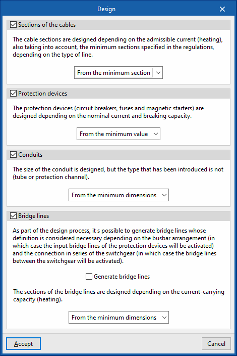
When users don't want the design to change the characteristics entered on a particular line or the characteristics of the protection elements of that line, the possibility to lock the design of that line or that element is provided.
To do this, the desired line is selected and the design is locked by pressing the padlock icon in the top right-hand corner of the corresponding box (it can be unlocked [open padlock] or locked [closed padlock]).
When this operation is carried out, padlock icons may appear on the single-line diagram next to each span of the circuit.
The icon can be red ![]() (indicating that the user has locked the design of an element of the switchgear or the design of the line routing), or green
(indicating that the user has locked the design of an element of the switchgear or the design of the line routing), or green ![]() (indicating that the user has locked the design of the cable section of that span).
(indicating that the user has locked the design of the cable section of that span).
Consult the checks carried out
Allows users to consult the checks made in the last analysis carried out in the job. After selecting the option, users can click on each of the lines to access a window for consulting the checks carried out on them.
As this action does not analyse or update the results, it speeds up the checking and modification of parameters.
If any modifications have been made to the elements in the system, the "Analysis" option must be used for the program to update the displayed results.
Show/Hide incidents
Activating or deactivating this option will highlight or hide marks in the tree and in the single-line diagram on the elements in which an error or warning has occurred in the last analysis. Hovering the mouse cursor over these marks displays a message indicating the existence of issues.
Short-circuit analysis
CYPELEC analyses short-circuit currents using the symmetrical components method in accordance with the IEC 60909 standard. This method, based on Thevenin's theorem and applicable to all types of networks up to 230 kV, consists of the induction of an equivalent voltage source at the short-circuit point and the replacement of each element of the fault loop by its corresponding direct, inverse and zero sequence impedances. Once this system has been established, the short-circuit current is obtained at the same point where the "virtual" voltage source was placed.
Thanks to its remarkable analytical aspect and higher accuracy compared to other procedures, it is the best tool for analysing system defects.
Scenarios for the analysis of short-circuit currents
The maximum and minimum short-circuit currents are checked for each of the established supply scenarios, if there is more than one, so that the protective devices ensure short-circuit protection for all power supply sources.
Calculating currents by unbalanced phases
When designing a three-phase electrical system, it is often assumed that the distribution of the loads in each of the phases will be balanced. This way of proceeding may be more convenient when considering the design, but it is only an approximation, as it is very difficult to achieve total balance. The possibility of designing the system with an unbalanced phase distribution makes it possible to select the phase to which each of the loads is connected. This makes it possible to carry out a preliminary study of the load distribution and avoid imbalances between phases that could affect the correct functioning of the system.
Furthermore, if the proposed system presents any imbalance between phases, the program will carry out all the relevant checks in order to model the real behaviour of the lines. In this sense, the currents circulating through each of the phases and the neutral phase will be taken into account to compensate for the imbalance between them, these currents will be considered when correctly designing the section of each conductor (including the neutral phase) and both the simple voltage drops (phase-to-neutral) and the compound voltage drops (phase-to-phase) will be calculated.
Then, in the tooltip that appears when hovering over the elements after the calculation, the calculated phase currents can be displayed by activating the corresponding checkbox from the "Results presentation" option in the "Project" group of the program's general interface.
Harmonic contents
Non-linear loads have a harmonic distortion index that can produce currents in the neutral conductor, in three-phase systems, when the neutral is distributed.
These neutral currents are due to phase currents which have a harmonic content (the most significant being the third harmonic) which is not cancelled out in the neutral conductor.
The value of the neutral current due to the third harmonic may be higher than the value of the phase current. In this case, the neutral current will have a decisive effect on the admissible current of the cables in the circuit.
When entering library receivers, users can define the total harmonic distortion rank 3 (THDI3).
The program evaluates the effect of harmonic currents and applies the reduction factors given in Annex E of IEC 60364-5-52.
Motors
The program checks the starting current of motors and allows the use of starters to reduce the starting current and thus limit its impact on the system. It also considers the contribution of asynchronous motors to short-circuit currents.
Checking the starting current of motors and the use of starters
When starting up, asynchronous motors require higher current levels than those they consume under nominal operating conditions. These overcurrents can generate very high voltage drops in the system, which is why the different electrical regulations limit the ratio between the starting current and the rated current depending on the power of each particular motor.
The program can set the starting data either by manually entering a rated current multiplier coefficient or by using the nomenclature of the American standard established by the NEMA code, which appears in the technical specifications of some motors.
A start can be selected to reduce the starting current and thus limit its impact on the system. The types of start that can be selected are as follows:
- For motors with single-phase or two-phase supply:
- Direct on line
- Variable frequency drive
- For motors with three-phase supply:
- Direct on line start
- Star - Delta start
- Autotransformer start (2 start points)
- Autotransformer start (3 start points)
- Variable frequency drive start
- Stator/Rotor resistance start
Not only does the selected starter affect the calculation, but it is also reflected in the single-line diagram with its corresponding icon.
Contribution of asynchronous motors to short-circuit currents
Due to the inertia of the motors at the time the short-circuit occurs, each of them transiently becomes a source of power generation that contributes to increasing the value of the maximum short-circuit current. For this reason, and following the guidelines of the IEC 60909 standard, this circumstance has been implemented in such a way that the real value of the short-circuit current in each of the lines of the system is taken into account.
Results output
Checking results on screen ("Single-line" tab)
After carrying out the analysis, the program displays the analysed results and magnitudes on the screen by means of a drop-down tooltip that appears when the cursor hovers over an element of the system.
Details on the elements in the single-line diagram represented on the screen can also be displayed in the same way as in the drawing representation.
If the "Show the same details as on the drawing" option is activated, these details can be configured from "Single-line diagram drawings" and also in the "Project" group of the general interface.
Reports by element ("Single-line" tab)
In the "Single-line" tab, by clicking on each element, the program can be used to consult the analysis reports and the detailed checks carried out on the element.
Each of the checks and the complete list of reports can be printed directly, or HTML, PDF, TXT, RTF or DOCX files can be generated with their contents.
VViewing checks ("Tree" tab)
The "Tree" tab includes a panel for viewing the checks carried out on each line.
To access the corresponding check report, click on the "Consult checks" option or double-click on the check to be displayed with the left mouse button.
Job reports
The program can also print the following job reports with the printer or generate HTML, PDF, TXT, RTF or DOCX files:
- Material schedule
Displays a report with the material schedule used in the system. The data on circuit breakers, fuses, magnetic starter, starters, differential switches, cables, conduits and other elements in the installation (such as meters or junction boxes) are organised in a series of tables that include the following information:- Code
- Unit
- Description
- Quantity
- Results table
Displays a report with the results of the system's analysis. This report includes the most relevant information for each of the lines as well as the results of the checks carried out, allowing users to decide which data appears in the tables and which does not. The program allows the following information to be configured:- Sorting line and protection tables (Joint / Separately)
The option of displaying line and protection information together or separately allows the selected data to be broken down into separate tables so that the tables fit the paper dimensions more conveniently and the visibility of the data they contain is improved. - Properties of the lines
Allows users to check or uncheck the displayed information related to the lines:- Description
- Phase
- Simultaneity
- Power (Calculated power, Installed power, Power demand)
- Power factor (cos φ)
- Length
- Section
- Insulation
- Installation method
- Intensity (Calculated current, Allowable current)
- Voltage drops (Voltage drop, Accumulated voltage drop)
- Conduit
- Properties of the protection devices
Allows users to check or uncheck the displayed information related to the protections:- Description
- Calculated current
- Nominal current
- Current-carrying capacity
- Maximum short circuit current (Iccmáx)
- Breaking capacity
- Short delay or magnetic firing current
- Current intensity
- Sensitivity
- Sorting line and protection tables (Joint / Separately)
Drawings of the single-line diagram in DWG, DXF or PDF format
This allows users to print the job drawings of the single-line diagram on any graphic peripheral that is configured on the computer, or to create DWG, DXF or PDF files.
The following options can be configured when editing the drawing:
- Type
- Dimensions
- Adjust the paper size to the scale
This way, through the scale, the desired size for the diagram can be selected, and the paper dimensions will be automatically adjusted for the layout. - Adjust the scale to the paper size
This way, the desired print format can be defined in order to frame the diagram in the formats supported by the printer. The program optimises the management of the free spaces in the diagram plan to allow a larger size in the texts that define the properties of each line. Thus, the drawing-text set reduces or increases its size to adjust its dimensions to those of the chosen paper format. An appropriate paper format should be selected, as too small a paper format could lead to an excessive reduction of the text, which would make it difficult to read.
- Adjust the paper size to the scale
- Scale
- Drawing configuration
- Detail of the single-line diagram
Three options are included in the single-line diagram drawing editing dialogue box to specify and configure the level of detail of the single-line diagram:- Complete
The complete single-line diagram is shown on a single drawing.- Detail of each preconfigured switchboard separately (optional)
- By switchboard/sub-switchboard
With this option, each switchboard and sub-switchboard is detailed separately in the single-line diagram. The program adds the reference of the particular switchboard or sub-switchboard, starting with its general protections. - Divide depending on configuration
In this case, the division of the single-line diagram can be edited to specify the maximum number of levels and lines:- Maximum number of levels
This parameter refers to the maximum number of vertical levels to be detailed and is related to the depth of the diagram. - Maximum number of lines
This parameter refers to the maximum number of lines/circuits to be represented horizontally and is related to the width of the diagram.
- Maximum number of levels
- Complete
- Detail of the single-line diagram
- Details
Files supported by BIMserver.center
When a project is exported to the BIMserver.center platform, a file in IFC format is automatically exported and, optionally, the bill of quantities reports and checks of the model elements for their integration in the Open BIM project, allowing them to be displayed:
- On the online platform;
- In the BIMserver.center app for iOS and Android.
Integration into the BIMserver.center platform
Many of CYPE's programs are connected to the BIMserver.center platform and allow collaborative work to be carried out via the exchange of files in formats based on open standards.
Please note that, to work on BIMserver.center, users can register on the platform free of charge and create a profile.
When accessing a program connected to the platform, the program connects to a project in BIMserver.center. This way, the files of the projects that have been developed collaboratively in BIMserver.center are kept up to date.

Options available in CYPELEC
In the "BIMserver.center" group of the main toolbar, either in the "Single-line" tab or in the "Tree" tab, there are the features needed to use CYPELEC together with other BIMserver.center tools:

Update
Updates information contained in models previously imported into the project or import new models if desired.
Share
Export the system information developed with CYPELEC to BIMserver.center to share it with other users, including the system's quantities and analysis reports.
During the export process, users can define information related to the identification of the files to be exported and the types of files that are generated:
- Name
- Description
- Additional files
- Quantities (optional)
- Reports (optional)
Direct connection to other programs
CYPELEC offers a direct connection option with Open BIM tools that allow users to continue their work.
- High-voltage
Allows work to be continued with CYPELEC Networks. This program receives the LV system's total power and considers it a point load for network analysis.

Licenses and related modules
CYPE programs are activated via electronic licenses which may contain one or more modules. The list of modules compatible with each program may vary depending on the product purchased and the type of license.
To consult the list of modules compatible with this program, go to "CYPE program modules".
Please note that the list of modules available in the license will depend on the product purchased.


