Introduction
CYPE Health and safety is a program created to assist users in the preparation of plans of collective protection elements to incorporate them into the Health and safety study included in the project. It also exports the measurements of the elements entered in FIEBDC-3 format to be processed by quantity surveying programs.
To work with CYPE Health and safety, the job must be linked to a BIM project and the program will import the floor structure to generate a floor plan for each of the imported floors. In each floor plan, the safety elements to be included in the job must be drawn.
With CYPE Health and safety, the construction phases of the project can be defined and the collective protection systems can be included in each of them.
Work environment
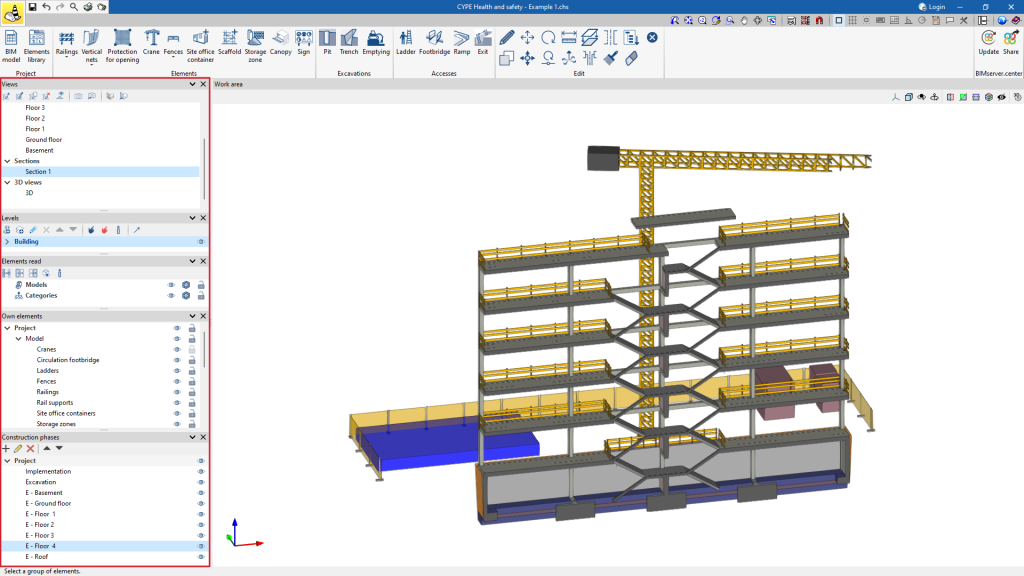
The CYPE Health and safety work environment features a system of dockable windows that can be customised to adapt the workspace to the project's needs.
The interface is divided into 3 main parts: the top toolbar, the sidebar and the work area.
The toolbar contains different features. Project elements can be created and managed, entered and edited.
The work area is located on the right side of the screen and is used to visualise the BIM model.
On the left-hand side are the main tools for defining the project views, as well as for managing the visibility of the elements read and the own elements. CYPE Health and safety also includes a tab for managing project phases and another tab for managing levels.
Workflows supported by the program
CYPE Health and safety is integrated into the Open BIM workflow through the IFC standard.
It offers a variety of workflow options:
- Importing models developed in CYPE Architecture.
- Importing models developed with different CYPE structural modelling tools. Included in this report are CYPECAD, CYPE 3D, CYPE Connect, StruBIM Steel, StruBIM Box Culverts, StruBIM Cantilever Walls, StruBIM Embedded Wall, StruBIM Shear Walls and StruBIM Rebar, among others.
- Importing model geolocations, maps, topographical surfaces, plots and neighbouring buildings from models created in Open BIM Site.
- Importing DWG, DXF, PDF and different image formats to use as templates for the BIM project.
- Importing projects developed in Autodesk Revit with the Open BIM - Revit Plugin.
- Extracting quantities and generating bills of quantities from the BIM model using Open BIM Quantities.
Creating a new job and linking it to a project
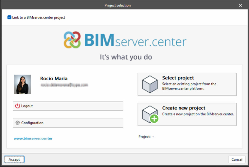
When launching the application and clicking on "New", users are given the option of creating a "New job", which can then be integrated into an existing project in BIMserver.center.
There is also the option to "Create new project". In this case, the created project will be visible from BIMserver.center from that moment on.
Once the new job has been created, users then access the interface, in which the graphic window showing the model or models that have been imported is displayed.
Users also have the option of starting the project without being linked to the BIMserver.center platform. To do this, simply uncheck the "Link to a BIMserver.center project" box in the top left-hand corner.
Files can be shared or imported at any time while the project is in progress via the BIMserver.center tab located at the top right of every program.
Importing BIM models
When creating a new job and selecting a project hosted on the BIMserver.center platform via "Select project", the "Import of BIM models" window appears, which shows the files contained in the project in IFC format.
The application offers users the option of including one or more of the existing models in the project. To do this, check the "Import" box and accept it.
When accessing the interface, the graphical window will display the imported models.
Importing DXF, DWG, PDF and JPG drawings
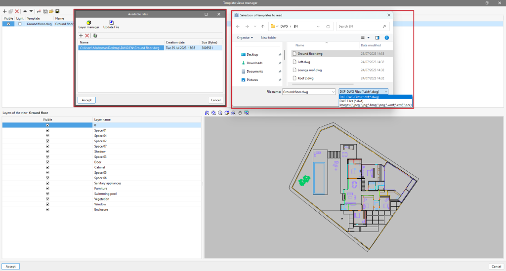
Clicking on the first tool, "DXF-DWG templates", will open a pop-up window called "Template views manager" in which templates can be managed and imported to the job in DXF, DWG, PDF or JPG formats, among others.
When clicking on the "Add" option, another window called "Available files" will appear. Here, a new file is added from "Add" and the type of format to be displayed is changed ("DXF-DWG files" appears by default). Select the file and accept the window. If the document consists of several pages, the "Page number" to be imported must be specified.
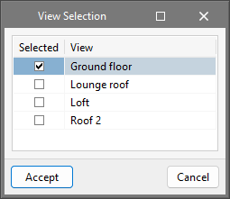
Once the templates have been imported to the job, select the tool located on the right, "DXF-DWG Templates (F4)", to proceed with the selection of views. Once the desired view has been selected, the window is accepted and it will appear in the graphic window of the current view.
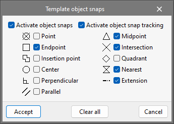
In order to snap entities or elements from the previously imported DXF or DWG file, the third tool, "Template object snaps (F3)", must be activated. From the pop-up window, the "Activate object snaps" checkbox and/or the "Activate object snap tracking" checkbox can be marked, along with the references that will be active.
Template transformation

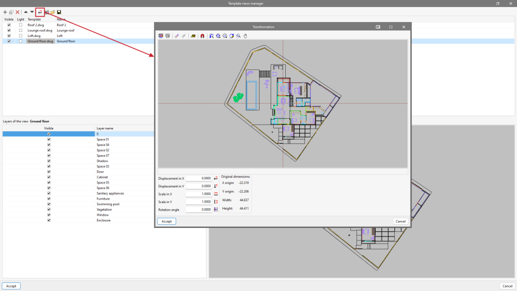
In "Template views manager", clicking on the tool with the red arrow will open a pop-up window called "Transformation", from which users can select the visible area of the template, apply a shift, rotate and/or change the scale, among others.
At the top of the window, we find a series of tools divided into groups:
- The first group allows users to "Select the visible area of the template" or restore the original area.
- The second group allows users to "Change the origin of the coordinates of a template" or reset it to the initial position.
- The third group, "Adjust the scale of a template", allows users to select two points on the template to create a segment with a known distance to adjust the scale of the template.
- The last group allows users to manage the visibility of the drawing view.
At the bottom of the window, we can enter numeric "Displacement" and "Scale" parameters on the "X" and "Y" axes or apply a "Rotation angle".
From the "Template views manager" window, the file containing the construction drawings must be added to the list and incorporated as many times as there are floors in the building.
Once the floors have been correctly renamed, each template can be transformed by selecting the visible area for each floor and changing the coordinate origin to a common (or easily identifiable) element in all of them. Lift shafts, staircases, columns, etc. are recommended as a reference.
Managing the element library

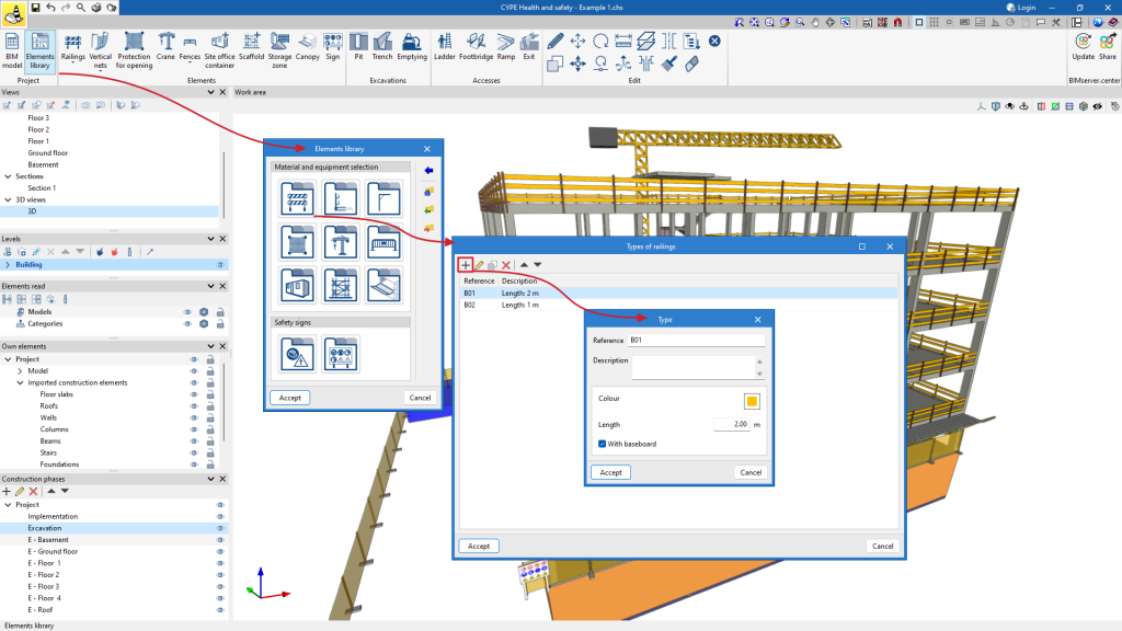
This feature can be used to customise a "Elements library" to be used when entering the elements. It is divided into two sections: "Material and equipment selection", where the types of handrails, vertical nets, shaft protections, cranes, fences, construction site huts, scaffolding and canopies can be defined; and "Safety signs", to adapt the signs to the user's needs.
Elements created in the project can also be exported for import into future projects.
The "Element library" makes it easier to enter data into the BIM model and is useful to establish classifications. Furthermore, its proper use will save time in project development, as any change in one type will affect all elements of that type entered in the model.
Material and equipment selection
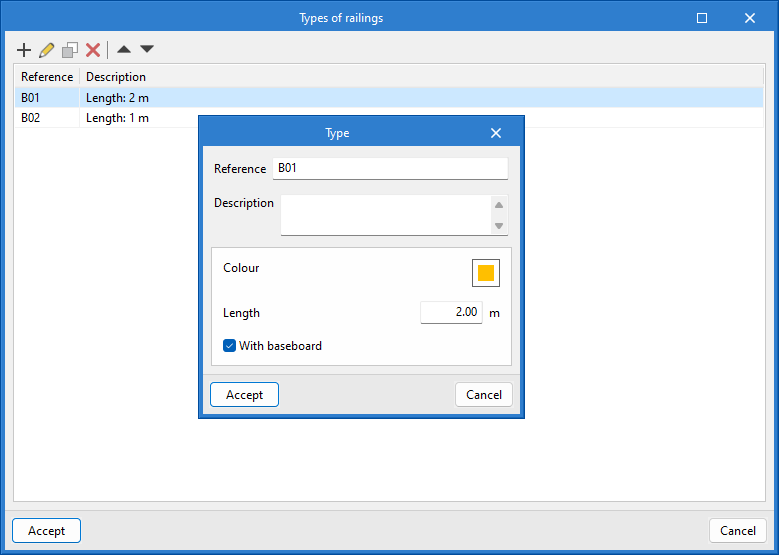
Types of railings
When creating a railing, the colour, length and even the baseboard can be configured by checking the corresponding box.
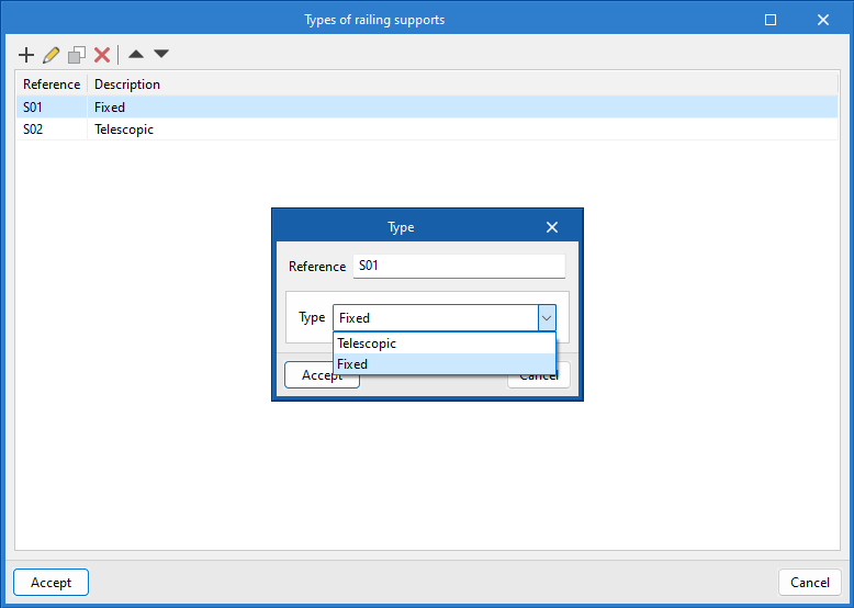
Types of railing supports
When generating a railing support there are two possible options: "Telescopic" and "Fixed".
Vertical net support types
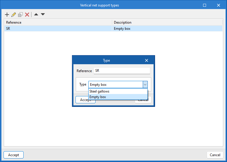
When adding a vertical net type, there is a choice between "Hollow box" and "Steel gallows".
Opening protection types
Types of cranes
Types of fences
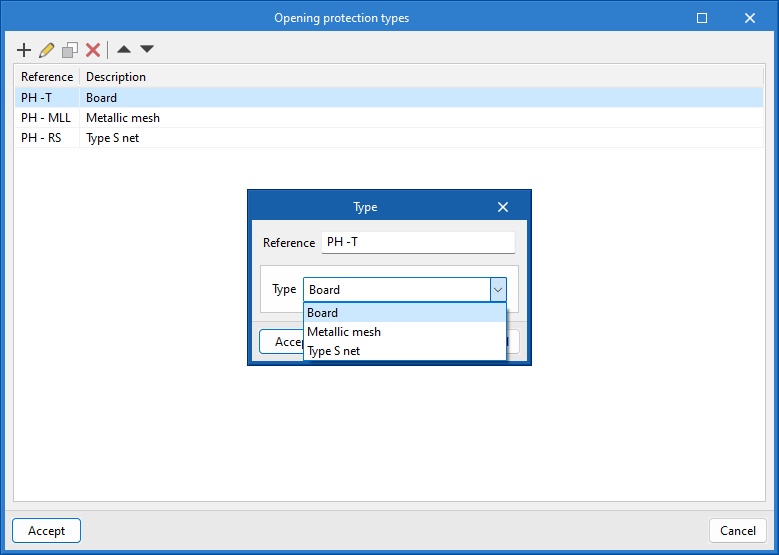
When adding an opening protection there is the option to choose between the following types: "Board", "Metallic mesh" and "Type S net".
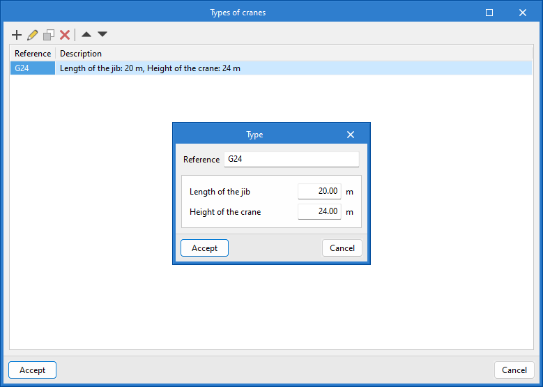
When configuring a crane, a certain dimension can be assigned to both the length of the jib and the height of the crane.
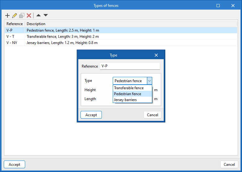
When creating a fence, there is a choice between the following types of fence: pedestrian fence, transferable fence and Jersey barriers. A height and length can also be assigned to the dimensions of the fence.
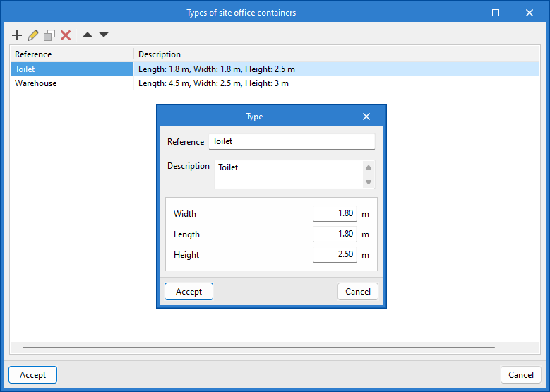
Types of site office containers
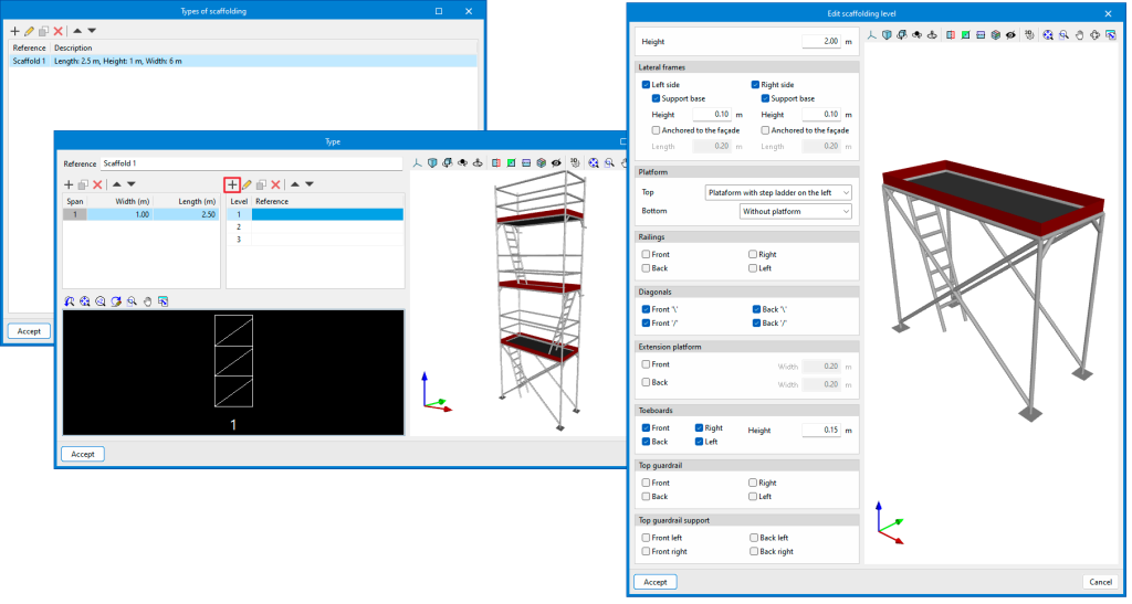
Types of scaffolding
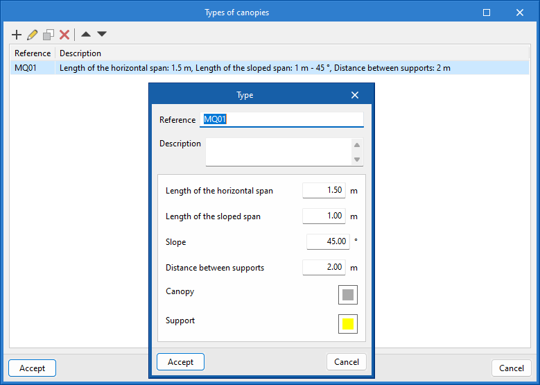
Types of canopies
When configuring a site office container, the dimensions of the width, length and height of the building can be specified.
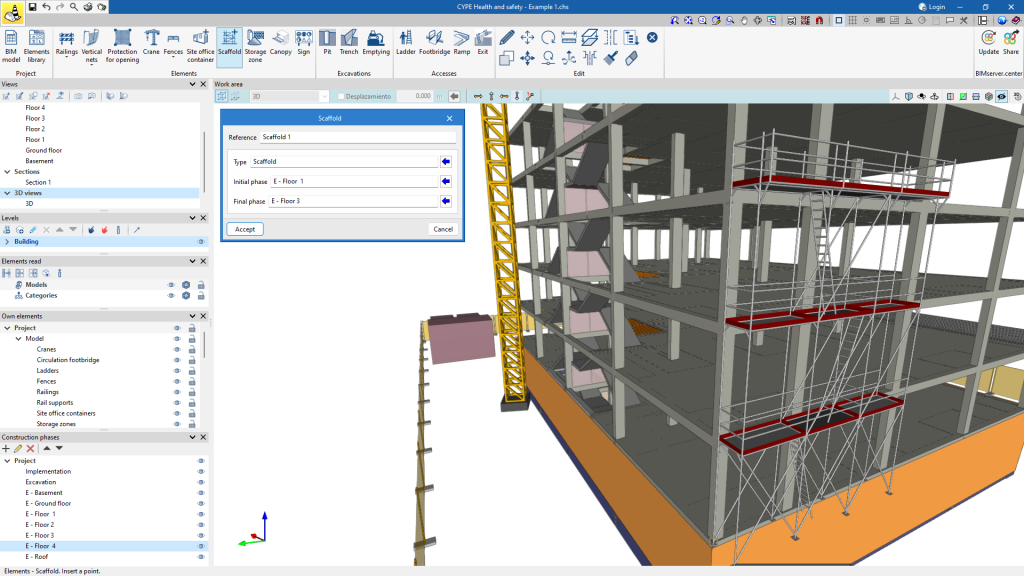
Creating scaffolding is the most complex case. They can be customised in terms of spans, width and length, and their levels can be customised using the "Edit scaffolding level" configuration panel.
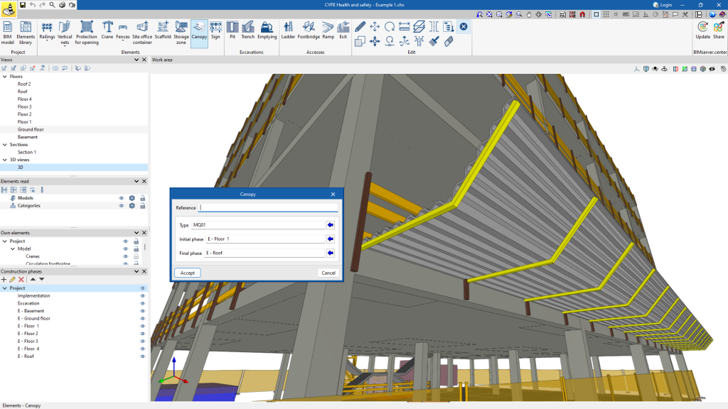
When adding a canopy, the length of the spans, the degree of the slope and the distance between the supports can be configured. Furthermore, both the canopy and the supports can be assigned a colour.
Safety signs
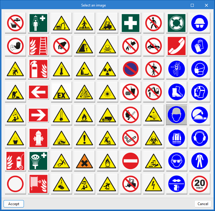
Safety sign catalogue
Types of safety sign
Type of risk indicator signs
Within the "Safety signal types" configuration, the catalogue of safety signals offered by the program by default is available.
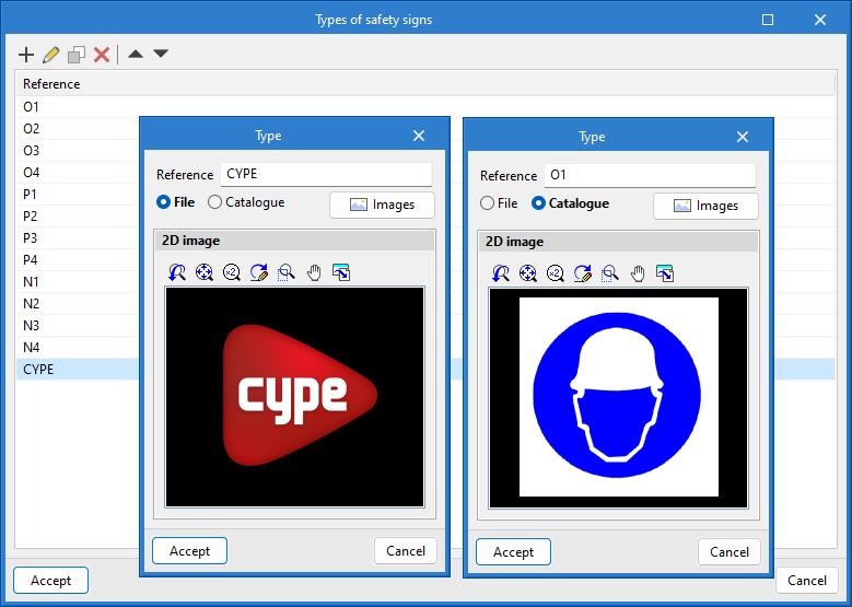
In the "Types of safety sign" option, users can create their own sign library. The program can be used to create the library from the catalogue or to insert external files in formats such as .jpeg, .jpg, .bmp, .png, .wmf, .emf and .pcx.
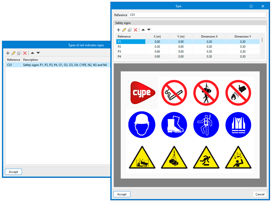
After all signs have been created, the hazard sign can be created. Using the reference of the safety sign, the safety sign can be identified and its dimension and location on the sign can be configured using the X and Y coordinates.
Entering elements

The "Elements" group contains the elements necessary for the health and safety study, such as collective protection systems, auxiliary means, site office container, storage zones and signs. From this group, it is possible to enter each of the elements in the BIM project.
When entering each of the elements, it is also possible to specify the period in which each element is required during the execution of the job, defining its initial and final phases. All this assigned data can be modified using the "Edit" tool.
Railings
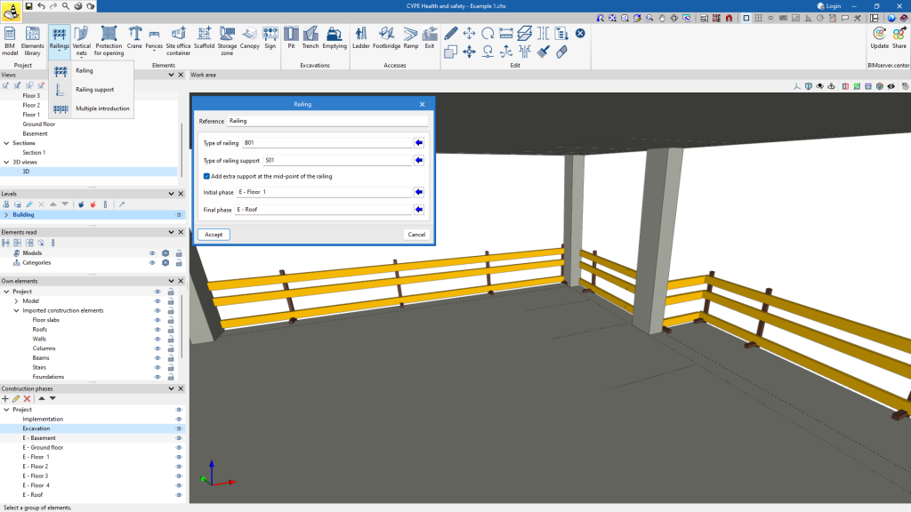
The program can be used to insert railings in two ways: individually, which allows the railing and the bracket to be inserted separately, or using the "Multiple entry" feature, which allows the railing and the bracket to be inserted at the same time.
Before insertion, the type of railing and support can be selected from the types created in the element library in the configuration window.
Redes verticales
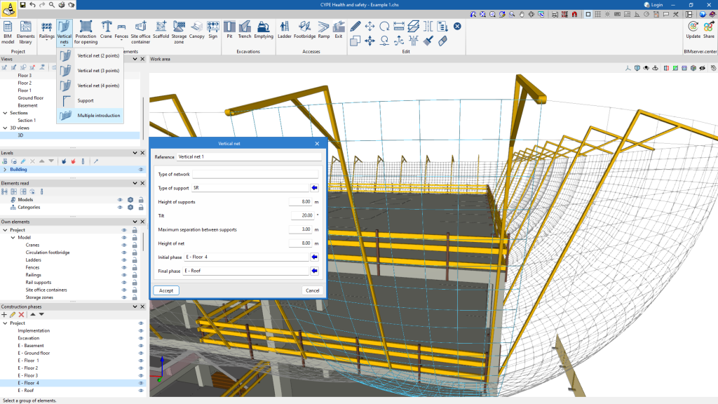
There are two ways to enter vertical nets: individually, which allows the net and the bracket to be entered separately, or via the "Multiple entry" feature, which allows the net and the bracket to be entered at the same time. The latter is the fastest way.
Before insertion, the type of support can be selected from the types created in the element library in the configuration window. It is also possible to set the height of the supports and the grid, the spacing between the supports and the inclination of the supports.
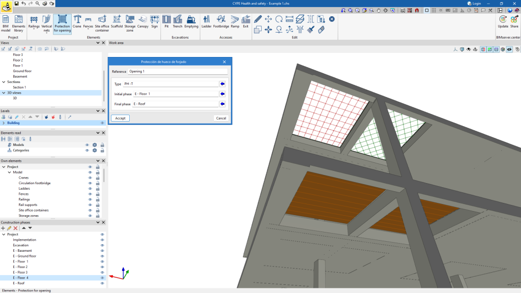
Protection for opening
To enter the protection for openings, the points that make up the opening to be protected must be selected.
Before insertion, the type of protection can be selected in the configuration window from the types created in the element library.
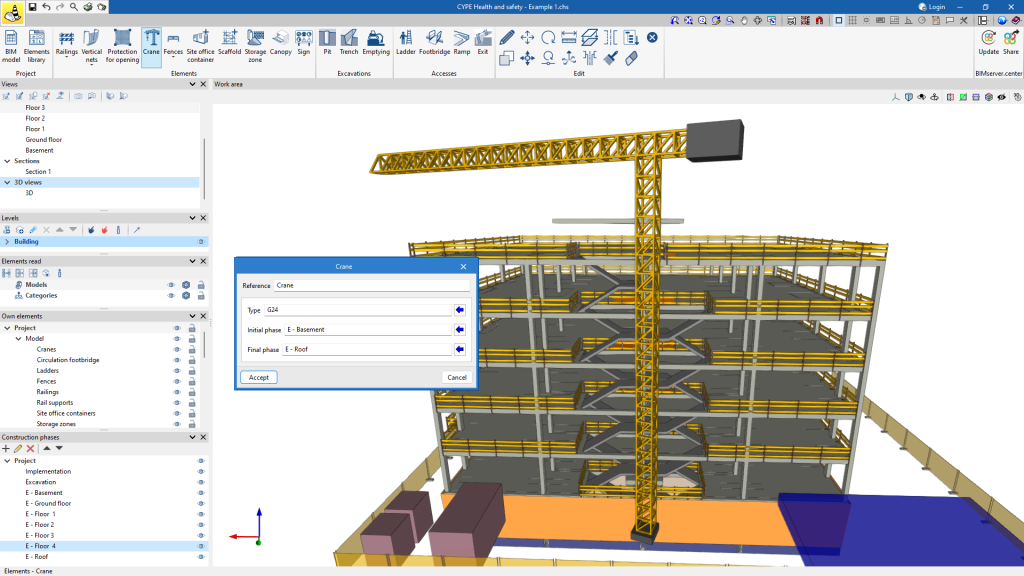
Crane
The program can be used to enter cranes by selecting the point where the crane is to be located.
Before insertion, the crane type can be selected in the configuration window from the types created in the element library.
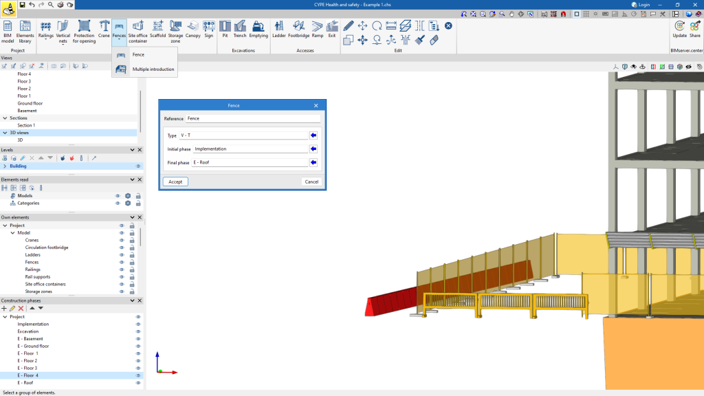
Fences
The program allows you to enter handrails in two ways: individually or using the "Multiple entry" feature. The latter is the fastest way.
Before insertion, the type of fence can be selected from the types created in the element library in the configuration window.
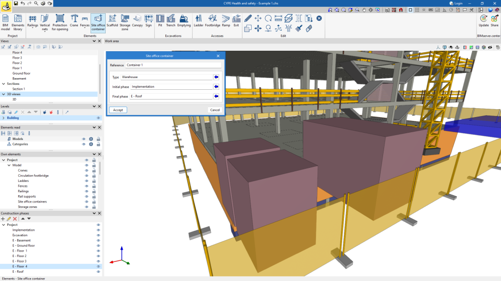
Site office container
It is very easy to incorporate a site office container in CYPE Health and safety. Simply select the point where it is to be located.
Before insertion, in the configuration window, you can choose the specific type of site office container from those available in the element library.
Scaffold
To incorporate scaffolding, simply select the desired location for the scaffolding.
Before starting the insertion, the type of scaffolding previously configured in the element library can be chosen in the pop-up panel.
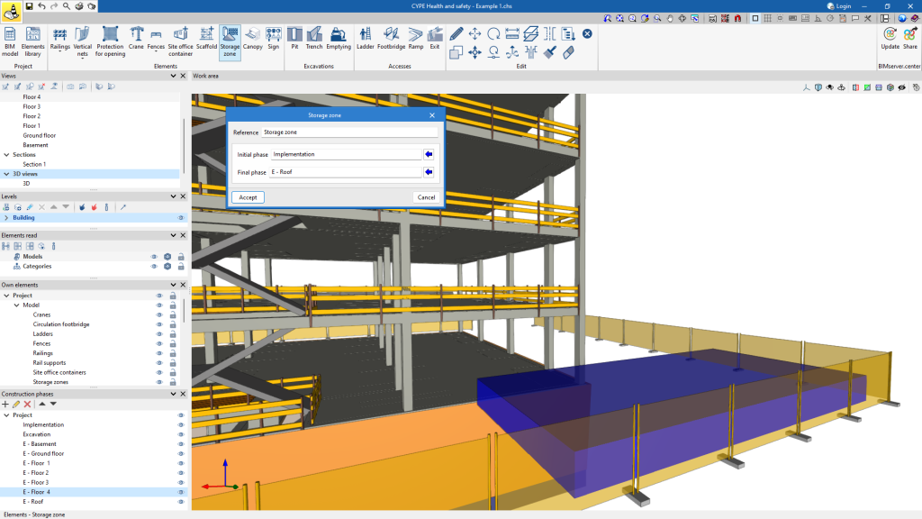
Storage zone
Locating the storage zones is very easy. Simply mark out the area with dots.
Canopy
Canopies can be inserted by selecting two points in the BIM model to indicate the length of the canopy.
Before insertion, the canopy type can be selected in the pop-up window from the types created in the element library.
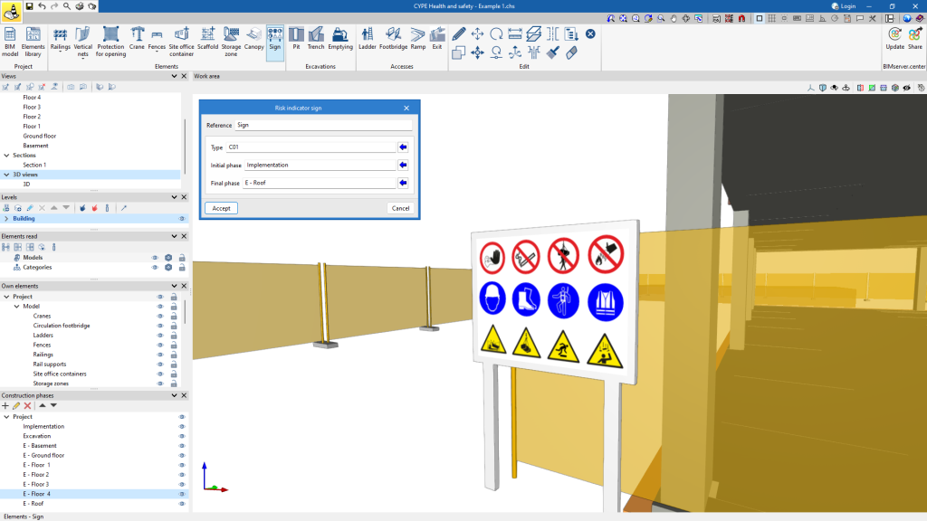
Sign
The program is used to insert signs by selecting the point where the sign is to be placed.
Before insertion, the type of risk warning sign can be selected in the pop-up window from the types created in the element library.
Entering excavations

Using CYPE Health and safety, the excavations required during the job phases can be located in the "Excavations" section. The period in which these excavations will be on the job can also be defined, specifying both their initial construction phase and their final phase. All this assigned data can be edited using the "Edit" tool.
When adding a "Pit", the type, either circular or rectangular, as well as the dimensions and depth of the pit can be specified.
When creating a "Trench" the width and depth of the trench, both initial and final, can be defined, allowing the exact dimensions of the trench to be set. The length of the trench is defined by two points in the working area.
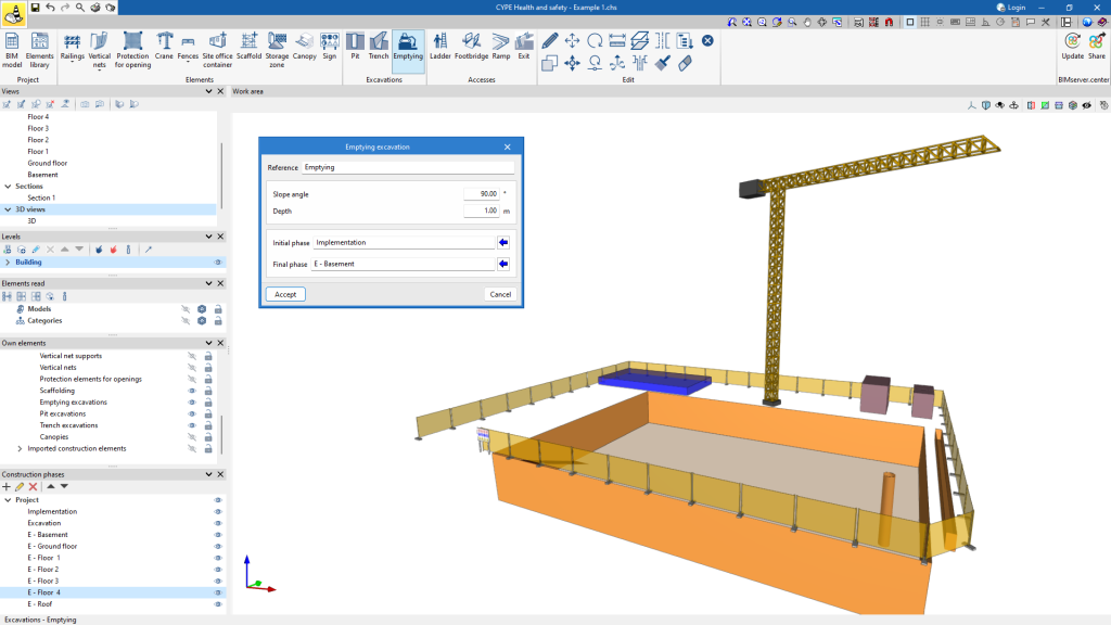
When adding "Emptying", the slope inclination and depth of the slope can be set. To complete the insertion, the perimeter of the excavation is simply delimited.
Entering accesses

The program can be used to enter the accesses required during the job phases in the "Accesses" section. The period in which these accesses will be in the job can also be defined, specifying both their initial construction phase and their final phase. All this assigned data can be edited using the "Edit" tool.
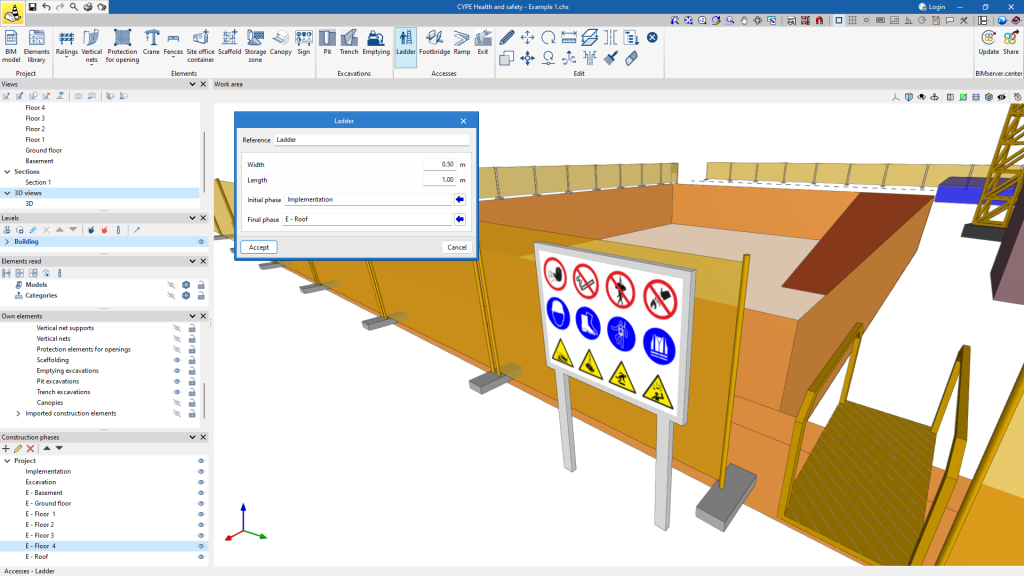
When adding a "Ladder" or a "Walkway", its length and width are specified.
When entering a "Ramp," the width can be defined. Two points in the work area define the length of the ramp.
"Exit" routes can also be entered, represented by dashed lines in the BIM model.
Editing tools

The main tools for editing the elements entered in the model are located in the "Edit" group of the main toolbar.
Some of these tools are common to other CYPE programs.
 | Edit | Selects an element in the model and edits its parametric properties. |
 | Delete | This works in the same way as the "Delete" key. |
| Move | Moves the selected items from a reference point. | |
 | Move a group of elements | Moves a group of elements. |
 | Rotate | Rotates the selected elements. |
| Rotate about an axis | Rotates a group of elements around an axis defined by two points. | |
| Copy | Copies elements including the same parametric properties. | |
| Copy onto another floor plan | Copies the selection onto another floor plan. | |
| Symmetry (copy) | Copies a selection of elements with symmetry about a vertical plane defined by two points. | |
| Symmetry (move) | Moves a selection of elements with symmetry about a vertical plane defined by two points. | |
| Modify height position | Modifies the height position of the selection. | |
| Assign phases | Assign an imported or inserted element to its corresponding phases. | |
| Assign selection | Assigns the selection. | |
| Measure lengths | Measures lengths by selecting two points. | |
| Show/Hide incidents | Controls the display of incidents. |
BIM model

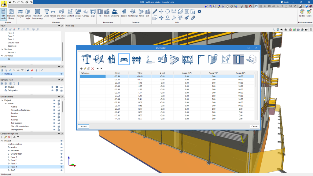
In the "BIM Model" window, there are several tables for reviewing or editing the data associated with the elements entered during the modelling process.
Existing element data can be modified from the toolbar. New elements can be added, existing elements can be edited, deleted individually or rearranged according to the user's needs.
The program can also be used to accurately adjust the position of each element in the 3D space by specifying the X, Y, and Z coordinates, which provides detailed control over the exact location of each element. There is also the option to adjust the angle of orientation of the elements to suit the specific requirements of the project.
Generating drawings

CYPE Health and safety allows the generation of sheets from the BIM model from the "Drawings" option.
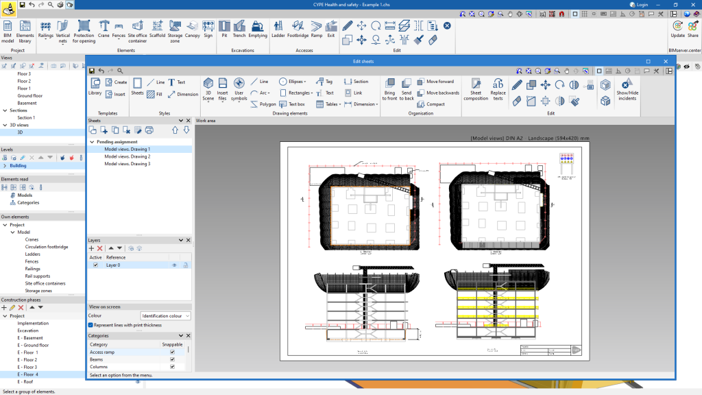
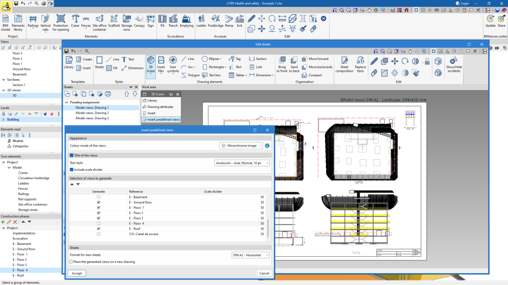
In the "Edit sheets" pop-up window, all the features for the layout of the project's sheets are available.
With this window, users can insert views, design, label elements, insert external files, create user symbols and generate tables, among many other options.
Predefined views
The program includes specific options to create health and safety study plans quickly and easily.
This provides predefined views one for each view of the model, one for each phase and one for each information sign. These views can be accessed from "3D Scene" under the option "Insert predefined view".
The parameters are configured in the pop-up window and the views to be inserted in the sheet are chosen. When accepted, the program will automatically distribute the selected views on the sheet.
Managing the visibility of project elements
The visibility of the different elements needed to model the project can be managed through three sections on the left side of the main interface of the program:
- Views: using this option, users can create, edit, save the start scene and return to the start scene.
- Elements read: these are the elements exported from other disciplines.
- Own elements: these are the elements created in the program in question.
- Levels: facilitates the association of model elements to various views, such as building plans or other reference planes.
- Phases: defines the construction phases of the project.
Managing views
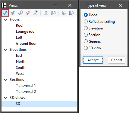
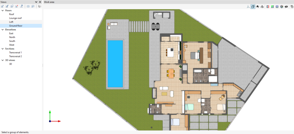
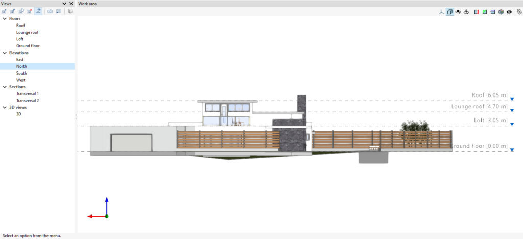
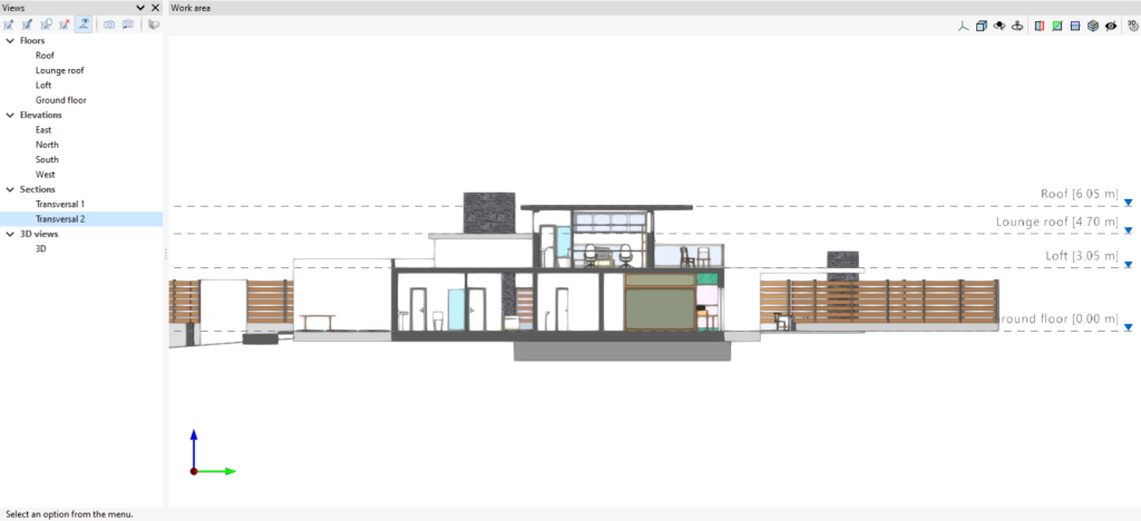
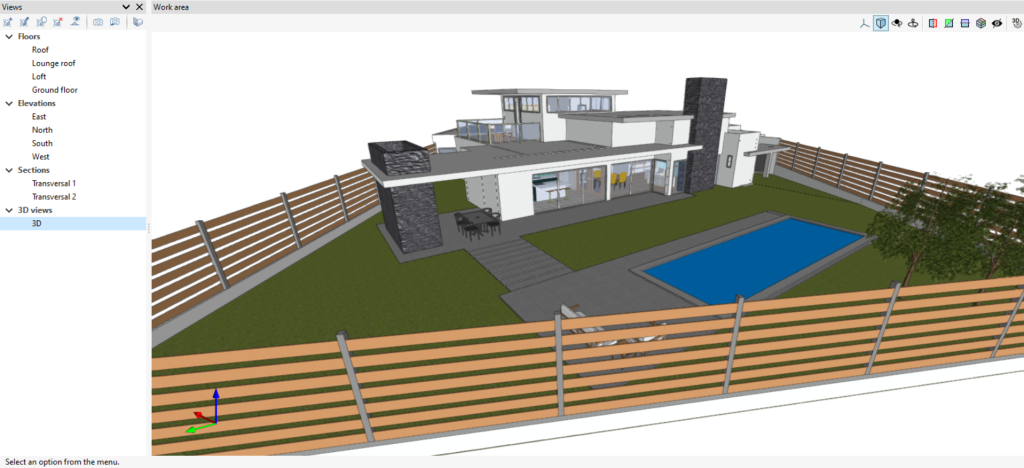
Programs with the "Views" section can create different views to make navigation and the architectural modelling process easier. The following types can be created: plan, reflected ceiling, elevation, section, generic and 3D view.
The following options are also available in the top toolbar:
- Create: creates a new 2D or 3D view of the model.
- Edit: modifies the properties of the current view.
- Duplicate: copies the current view.
- Delete: deletes the current view.
- Show references: by selecting this option, references to other views will be displayed in the active view.
- Save the start scene: sets the current position of the view as the start scene.
- Go to start scene: orients the current view to the position of the start scene.
- Define: specifies the working plane associated with the current view. The work plane serves as the basis for the entry of the model components.
- Go to the workplane: orients the current view to the position of the work plane.
View range
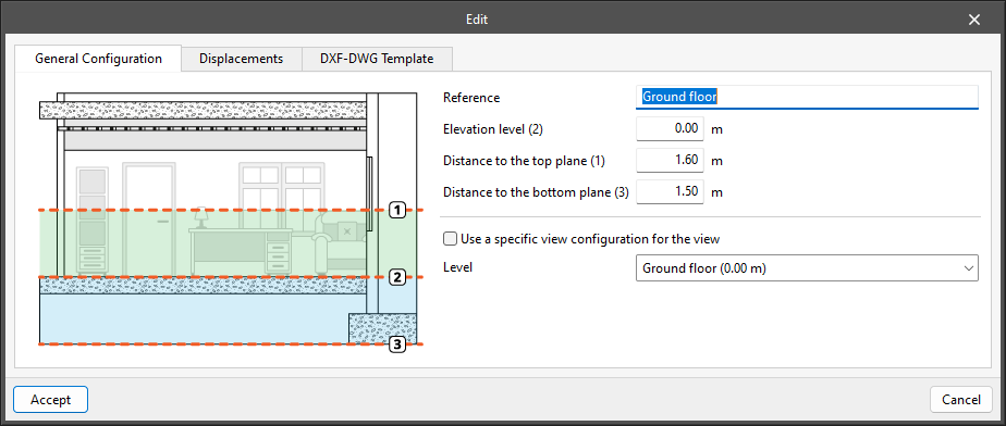
In the "Edit" panel of the view, users can specify the distance to each of the planes from the origin of the view.
All view types, except the 3D view, have an associated region bounded by two planes, which determines the elements to be represented in the view.
In elevation views, section views and generic plans, the rear plane is the plane perpendicular to the direction of view in a positive direction. The front plane is the same but in a negative direction.
Managing elements read
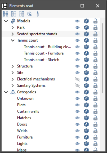
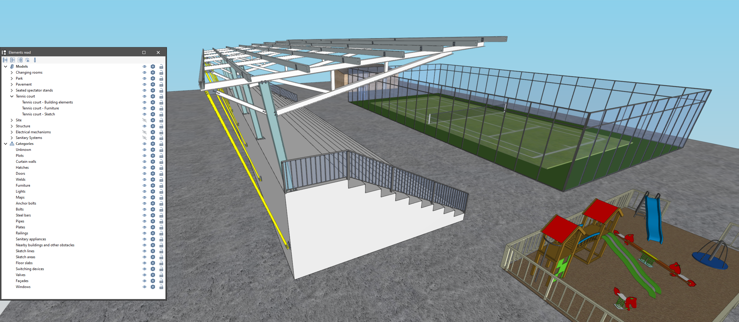
The management of the elements from the digital model of the building, obtained from the associated BIM project, is carried out from the "Elements read" menu located on the left sidebar of the application.
The elements read are structured in the form of a tree according to two types of classification:
- By "Models": users can inspect each contribution linked to the job and, within this, each associated 3D model.
- By "Categories": allows users to group the "Elements read" into families according to their characteristics.
Three buttons are displayed next to each component of the tree:
- Visible
Enables or disables the visibility of the elements. - Visualisation mode
Allows users to toggle between normal, transparent and wired display modes. - Snap
Allows users to enable or disable object snaps of the elements.
The following actions can be carried out via the toolbar in the top left-hand corner:
- Isolate selection
Allows users to isolate elements of the 3D model. By selecting the elements of the 3D model to be isolated and clicking the right mouse button, the rest of the elements of the model will disappear. - Hide
Allows users to hide the selected elements. By selecting the elements of the 3D model to be hidden and right-clicking on them, they will disappear. - Show all
Shows all hidden elements. - Appearance
Allows users to choose between normal drawing or monochrome drawing. - BIM information
Displays a panel with the attributes associated with the selected component.
Managing own elements
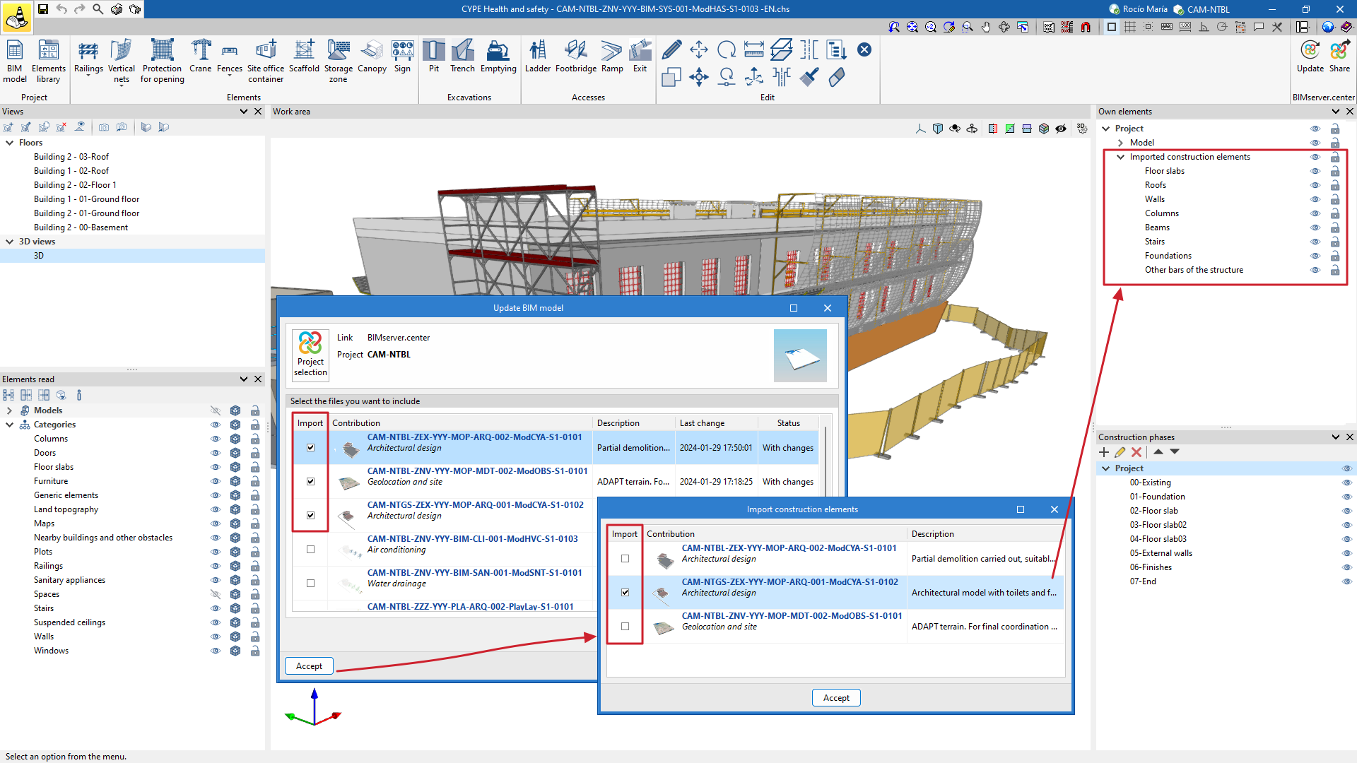
From the "Own elements" section, users can control the visibility and blocking of elements. In CYPE Health and Safety, they are divided into "Model" elements and "Imported building elements."
"Model" elements are all those elements specific to the program that have been entered to generate the Health and safety plan, such as canopies, fences, cranes, ladders, etc.
In CYPE Health and safety, in addition to importing contributions present in the shared project, users can select the contributions from which they wish to import the building elements. These "Imported building elements" will become part of the CYPE Health and safety work file and can be used as their own references, associated with construction phases.
This possibility allows users to decide, for example, whether the building elements to be imported are those from the architectural model or those from the structural model (even if both are visible in the work environment).
Level management
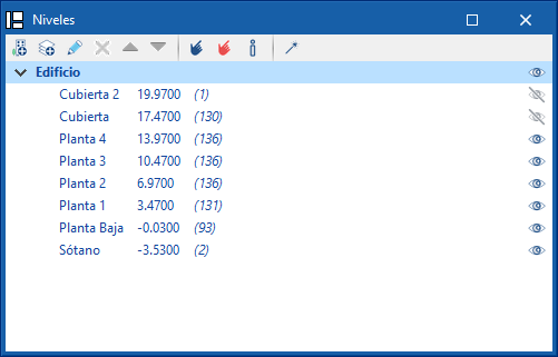
The "Levels" section makes it easy to associate elements of the model to various views, such as building plans or other reference planes. There is a drop-down list of buildings and levels defined in the model.
The toolbar allows new buildings and levels to be added to the model. Next to each level, the elevation is shown along with the number of associated model components in brackets. It is also possible to activate or deactivate their visibility in the work area.
With the "Assign elements to a level" option, components of the model can be selected from the work area and associated to the level selected in the list. The "Unassign elements to a level" option allows the reverse operation to be carried out.
From the "Information on the level of an element" option, users can inspect an object from the workspace and obtain its current level.
Finally, the "Automatic assignment" option associates the components of the model to the defined levels automatically. To do this, the geometry of the element is analysed and the level immediately below it is searched for.
Managing construction phases
CYPE Health and safety is used to define the construction phases of the project, which are particularly important in the planning of the safety measures required for the execution of the project.
Once these phases have been defined, users can specify which elements are available in each phase by entering them into the BIM model. This flexibility results in precise control over the inclusion of elements at each stage of the project, making it easier to manage safety at each stage of construction. In addition, these phases can be edited, deleted and ordered.
Additionally, the visibility of each of them can be controlled. This allows users to focus on the relevant phases at any given moment, which facilitates visualisation during modelling.
Elements imported from other disciplines can be assigned phases using the "Assign phase" tool in the editing group. The imported elements are needed as a context for documenting the layout of the collective protection elements.
Results output
Drawings from "Edit sheets"
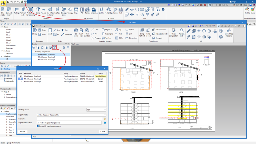
Click on "Drawings" to open the "Edit sheets" window. In the "Drawings" section, users will find the button for printing the generated PDF, DWG and DXF drawings.
In addition, users can choose whether they want to export in a single file, or whether they want to export each sheet in a separate file.
The program also exports scene views as a vector image or as a rendered image.
Export to FIEBDC-3 format
CYPE Health and safety exports the measurements of all the safety elements defined in the project to the standard FIEBDC-3 format.
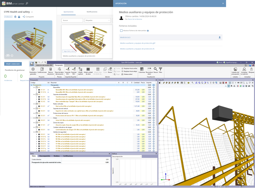
By sharing the project via BIMserver.center, the .bc3 file will be available on the platform with the measurements of the elements entered. The file is simply downloaded from the BIMserver.centre platform and imported into the user's preferred program for budgeting, such as Open BIM Quantities.
Integration into the BIMserver.center platform
Many of CYPE's programs are connected to the BIMserver.center platform and allow collaborative work to be carried out via the exchange of files in formats based on open standards.
Please note that, to work on BIMserver.center, users can register on the platform free of charge and create a profile.
When accessing a program connected to the platform, the program connects to a project in BIMserver.center. This way, the files of the projects that have been developed collaboratively in BIMserver.center are kept up to date.

Options available in CYPE Health and safety

In the upper right-hand corner of the main toolbar, there are the tools needed to use CYPE Health and safety together with other BIMserver.center tools.
Importing and updating BIM models
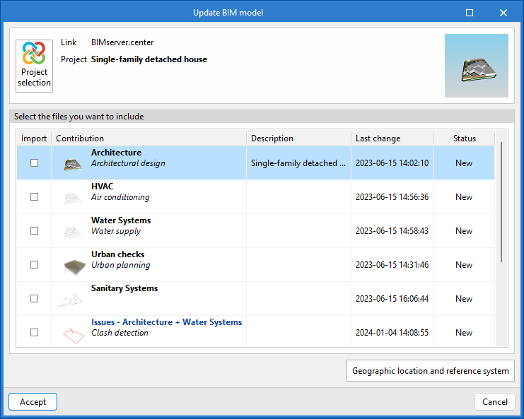
The "Update" option allows users to update the information contained in the models previously imported into the project, or to import new models if desired.
In the "Update BIM model" window, by clicking on the "Project selection" option, users can choose the project to be connected to the CYPE Health and safety BIM model from the user's list of projects in BIMserver.center.
Via the "Geographical location and reference system" option it is possible to set the geographical location data and the reference system of the model.
Sharing the BIM model with other users
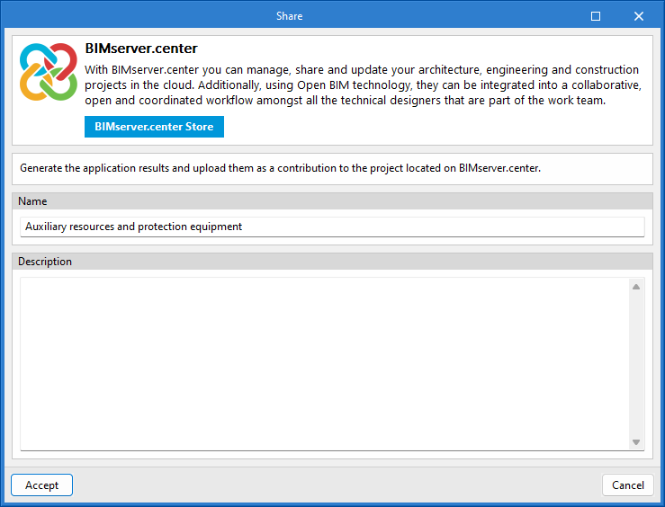
Using the "Share" option, the information contained in the model developed in CYPE Health and safety can be exported to the BIMserver.center platform.
During the export process, a name and description can be added to the project. In addition, when sharing the project from CYPE Health and safety to BIMserver.center, three files linked to the project will be created by default: the measurement file (.bc3), the GLTF file (.gltf) and the IFC file (.ifc). These files can be downloaded from the BIMserver.center platform.
Licenses and related modules
CYPE programs are activated via electronic licenses which may contain one or more modules. The list of modules compatible with each program may vary depending on the product purchased and the type of license.
To consult the list of modules compatible with this program, go to "CYPE program modules".
Please note that the list of modules available in the license will depend on the product purchased.

