As of the 2018.a version, CYPE 3D allows for the main specifications and requirements linked to the three most common seismic resistant systems defined in the American AISC 341-10 code (Seismic Provisions for Structural Steel Buildings) to be included in the design of welded and rolled steel structural elements:
- Moment-resisting frames
- Frames with concentric bracing
- Frames with eccentric bracing
Also implemented is the analysis, design and check of Prequalified Connections in accordance with the ANSI/AISC 358-10 and ANSI/AISC 341-10 codes. The design and check of Prequalified Connections are exposed in detail in the section on “Prequalified connections in accordance with ANSI/AISC 358-10 and ANSI/AISC 341-10” of this webpage. These connections are applied to earthquake-resistant systems composed of “Moment-resisting frames”.
The following sections describe the three earthquake-resistant systems that are contemplated and the types into which they are sub-divided. The checks carried out by CYPE 3D for each type of system are described in the “Checks carried out” section of the “CYPE 3D, Earthquake-resistant systems in accordance with ANSI/AISC 341-10, and prequalified connections in accordance with ANSI/AISC 358-10 and ANSI/AISC 341-10” webpage, which will be available shortly.
Moment-resisting frames
Unbraced frames or moment-resisting frames are an assembly of straight beams and columns connected to one another with welds, bolts or both. The bars making up these frames are mainly exposed to bending moments and shear forces, which control their design.
The specifications of AISC 341-10 consider three types of moment-resisting frames in accordance with the grade of ductile behaviour considered in the design. The fundamental difference between them is that they are designed with different energy dissipation levels:
- OMF – Ordinary Moment Frames (AISC 341-10, E1)
- IMF – Intermediate Moment Frames (AISC 341-10, E2)
- SMF – Special Moment Frames (AISC 341 -10, E3)
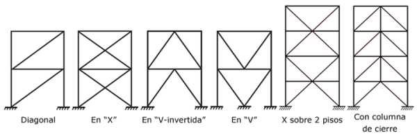
Frames with concentric bracing
This type of structure is characterised because the central axes of the component structural members are cut at a point, forming a grid-like structure. This is why lateral actions mainly induce axial forces in the bars of the braced frame.
The specifications of AISC 341-10 consider two categories for concentrically braced frames depending on the expected performance level:
- OCBF – Ordinary Concentrically Braced Frames (AISC 341-10, F1)
- SCBF – Special Concentrically Braced Frames (AISC 341-10, F2)
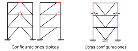
Frames with eccentric bracing
In eccentrically braced frames, axial forces induced in the braces are transferred via shear forces and moments in segments of a reduced length (e), called links, where energy, due to creep of the steel, is dissipated. The links represent “structural fuses”, which should be detailed adequately to avoid local buckling and other instability phenomena from degrading the response.
The specifications of AISC 341-10 consider a single category of frames with eccentric bracing:
- Eccentrically braced frames – EBF (AISC 341-10, F3)
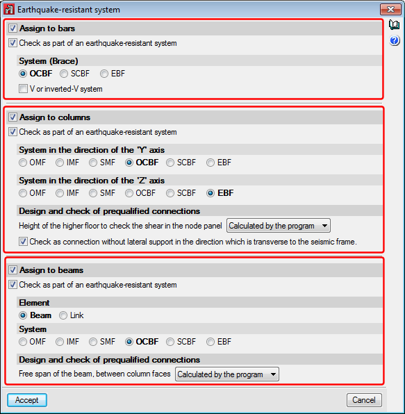
Assignment of earthquake-resistant systems in CYPE 3D
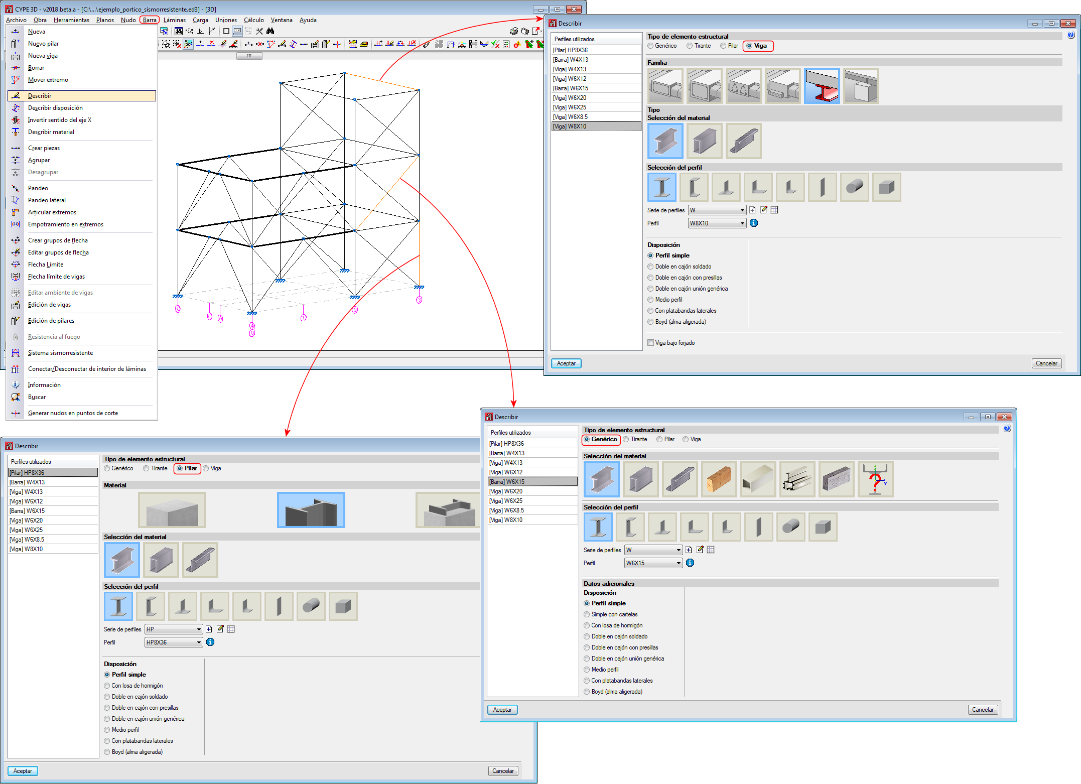
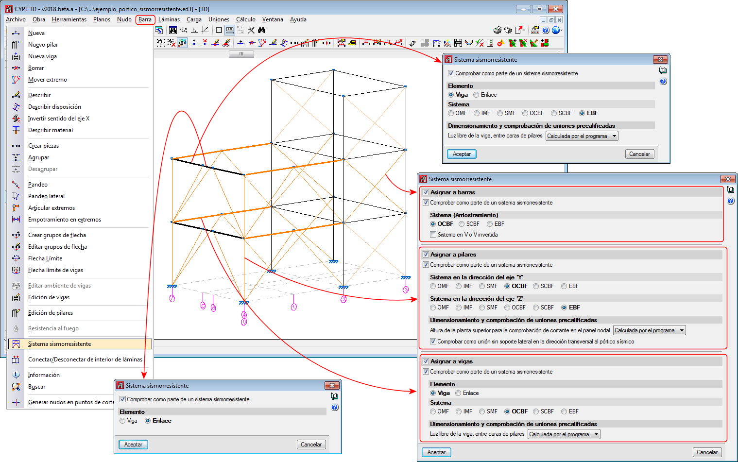
Users can assign earthquake-resistant properties to a bar using the “Earthquake-resistant system” option of the “Bar” menu. This option is only available if the selected rolled steel code is “ANSI/AISC 360-10”.
Users can freely assign the earthquake-resistant properties to bars and in accordance with their own criteria. Logically, it should be coherent with the geometry of the frame.
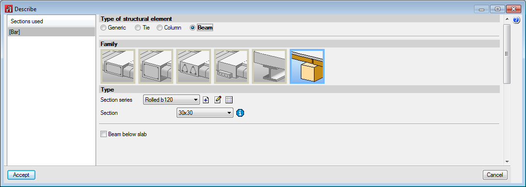
Bars that have been assigned earthquake-resistant systems must be rolled or welded steel bars and be defined as Generic bars, Columns or Beams.
- Generic structural elements (bracing)
Generic-type bars are those which are going to be used as bracing, and so, it is only possible to assign OCBF, SCBF or EBF systems to them. - Column-type structural elements
Any of the indicated earthquake-resistant systems (OMF, IMF, SMF, OCBF, SCBF or EBF) can be assigned to Column-type bars in the direction of the local “Y” and “Z” axes. The earthquake-resistant system can be different in either direction.
When checking prequalified connections and if the selected earthquake-resistant system is IMF or SMF, it is possible to indicate if the “Height of the higher floor to check the shear in the node panel” is calculated by the program or if it is indicated by users. It is also possible to activate the option: “Check as connection without lateral support in the direction of the seismic frame”, which is applicable to connections of SMF-type frames. More information on these two options can be found in the sub-section: “Operation in CYPE 3D” (including the section: “Prequalified connections in accordance with ANSI/AISC 358-10 and ANSI/AISC 341-10”). - Beam-type structural elements
Beam-type bars can be assigned any of the indicated earthquake-resistant systems (OMF, IMF, SMF, OCBF, SCBF or EBF) if the “Beam” option is selected as the “Element”. If users select the “Link” option as the “Element”, no type of system will be available to be assigned, because “Links” correspond to EBF earthquake-resistant systems, which is the type that is assigned automatically.
When checking prequalified connections, if the “Beam” option is selected as the “Element”, users can mark if the “Free span of the beam, between column faces” is to be calculated by the program or defined by users. More information on these two options can be found in the sub-section: “Operation in CYPE 3D” (including the section: “Prequalified connections in accordance with ANSI/AISC 358-10 and ANSI/AISC 341-10”).