Update history​​

CYPE Architecture

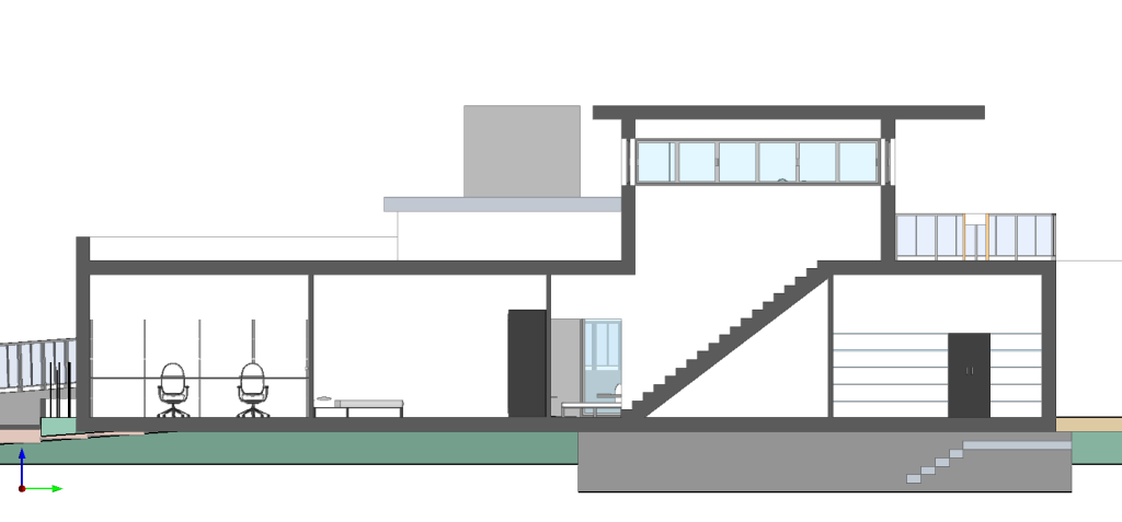
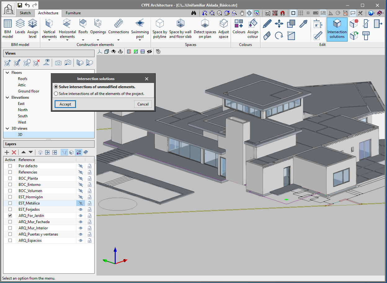
Intersection solutions allow all the intersections in the job to be easily solved (walls with walls and walls with floor slabs), either manually or automatically.

When modelling walls and floor slabs in CYPE Architecture, the intersections are not solved at the same moment as they are inserted. It is later on, when the building model has been introduced, that these intersections can be solved, either automatically or manually. To do this, there is a section for intersection solutions in the "Edit" group of the toolbar:

  • Automatic intersection solutions

    Allows all the intersections in the job to be automatically solved. If clicking on the "Intersection solutions" button, a panel appears that allows users to choose between "Solve intersections of all elements of the project" or "Solve intersections of unmodified elements".

    If it is the first time that the user is dealing with intersection solutions in a certain project, the "Solve intersections of all elements of the project" option must be chosen. If users have previously solved some intersections before and they do not wish for these intersections to be lost, the "Solve intersections of unmodified elements" option must be chosen.
  • Manual intersection solutions

    The tools for manually solving intersections allow the user to solve intersections that have not been automatically generated. These tools are:

    • Cut by plane
      Allow walls, floor slabs, columns and beams to be cut by a certain plane in order to solve an intersection. To do this, a section plane must be defined and the elements on which it will act must be selected:

      1. Click on the "Cut by plane" button.
      2. Define the section plane. A plane from one of the faces of the architectural elements can be chosen, or drawn manually.
      3. The defined plane will be drawn on the screen with a green arrow. The direction of the arrow indicates the part of the element that will be cut by the plane and that will remain, whilst the opposite side of the arrow indicates the part of the element that will be cut and deleted.
      4. Finally, choose the element or elements to be cut using the defined plane.
    • Extend face
      Allows the face of a particular element to be extended in order to solve an intersection. The steps to follow are:

      1. Click on the "Extend face" button.
      2. Choose the face of the element to be extended.
      3. Extend it to the other element or a fixed distance using the "allows for dimensions to be defined upon introducing each element" button.
    • Subtract
      Allows two elements to be subtracted whilst maintaining both parts. For example, an intersection in the meeting of two walls in which one of them is uninterrupted. The steps to follow are:

      1. Click on the "Subtract" button.
      2. Choose the element that will be cut.
      3. Choose the element that will be continuous.
    • Delete
      Allows users to delete part of an element that has been divided in two by subtraction.
    • Regenerate
      Allows an element to be regenerated and returned to its original state.
  • In walls
    • New basement wall category. Allows for an improved connection with Open BIM Analytical Model.
    • The walls capture ramps, stairs and lifts.
    • Automatic regeneration of the 3D model of the walls after clicking on accept in the BIM model panel.
    • Correction of an error when drawing the wall by polyline on a sloped surface.
    • Correction in the export of the net and gross area so it can be correctly read in Open BIM Quantities.
  • In curtain walls
    • The “Opening” button also deletes the mullions and transoms from the curtain wall.
    • The export of the curtain wall mullions has been corrected so that it can be correctly read in other programs.
  • In louvres
    • The louvre is drawn on screen at the same time as it is being inserted, in the same way as for the curtain wall.
  • In columns
    • The rotation angle of the column can be indicated upon being inserted. Columns introduced successively will appear in the same direction.
    • When editing the size of the column it moves.
    • The column does not rotate when using the “Rotate” button in the “Edit” menu.
  • In floor slabs
    • A new category of external floor slabs has been included, which allows for improved connection with Open BIM Analytical Model.
    • Correction in the export of the net and gross areas so that they can be read correctly in Open BIM Quantities.
  • In windows
    • The windows include the adjustment of the frame.
    • When a window is inserted, its position of alignment with the wall can be chosen.
    • The same insertion point is maintained for all windows introduced simultaneously.
  • In doors
    • The button "Change opening direction" has been included in the menu to change the opening direction of the doors.
    • The doors include the adjustment of the frame.
    • When a door is introduced its position of alignment with the wall can be chosen.
    • The drawing of the doors has been corrected when choosing any insertion point.
    • The error produced when inserting a door into a sloped wall has been corrected.
  • In openings
    • New opening by points feature with the “Opening” button.
    • When an opening is inserted its insertion point can be chosen.
    • The error produced when deleting an opening dependent on a door has been corrected.
  • In roof tiles, ridges and valleys
    • Improved capture of perpendicular, tracking and intersection types.
    • Improvements in drawing the label on the space.
    • It is possible to change the size of the text drawn on the space.
  • In furniture
    • A button has been included which allows for the simultaneous rotation of various items of furniture.
    • The error produced when introducing cupboards and worktops and clicking “shift” at the same time has been solved.
  • In the BIM model
    • The BIM model shows all the element data, including the label and the level.

Two new features have been introduced in the “Edit” menu of the “Architecture” tab toolbar:

  • Copy properties
    Allows properties (Reference, Level, Label, Colour, etc) to be copied between elements of the same type.

To copy the properties of an element follow the steps below. Remember that properties can only be copied between elements of the same type.

  1. Click on “Copy properties” in the “Edit” menu.
  2. Select the element whose properties you wish to copy.
  3. A window will appear with a list of properties that can be copied and their values.
  4. Choose the properties to be copied and click on accept in the panel.
  5. Select the elements where the selected properties will be copied.
  6. The properties will be automatically transferred to the selected element.
  • Measure area
    Allows the measurements of an area to be obtained by selecting on screen the points of the polygon that define it. Both the area and the dimensions of the perimeter lines outlining the polygon are obtained.

    The dimensions are saved in the program and can be viewed again at any time by clicking on the “Measure area” button again. To delete the saved areas from the memory click on “Delete measurements”.

Improvements and corrections have been made to the following functionalities: walls, curtain walls, columns, floors, windows, doors, openings, spaces, tiles, roof ridges and valleys, and furniture.

This new feature is available in CYPE Architecture and in any program with a 3D CYPE interface. The section filling allows the model to be viewed more clearly, thus avoiding some display problems that existed in plan and in section.

To view the fill correctly in the other BIMserver.center applications, you must re-export the project from "CYPE Architecture".

Since the previous version (2021.b), CYPE Architecture has an option with which users can edit the colour of the elements of the "Architecture" tab using the "Colours" button.

Taking advantage of this tool, in the 2021.c version, the "colours" panel also allows users to assign a texture to each colour of the library, and so, give the model a more realistic appearance.

The library contains 43 textures that are classified by groups (timber, concrete, stoneware, marble, steel, stone, brick and grass).

From the layers panel, users can show or hide textures during the modelling process.

The textured model can be viewed both on the BIMserver.center platform and in the rest of the Open BIM workflow programs.

In this version of CYPE Architecture, you can find direct links to other applications that are available on BIMserver.center to continue to develop your project.

This way, you can add more information to your architectural model, such as: describe the construction solutions for each architectural element; check the urban regulations of your municipality; measure the model to obtain price estimates; arrange the electrical mechanisms for their subsequent design; or compose your project drawings.

  • Construction solutions: After developing your architectural model, you can specify the construction solutions you want to use (type, composition by layers, materials, technical properties, etc.) This way, and using the Open BIM workflow, in addition to documenting your project, you will increase the quality of the information that is transmitted to the later phases of the workflow (thermal and acoustic analysis, bills of quantities, etc.). See more…
  • Electrical mechanisms: You can arrange the electrical mechanisms (switches, socket outlets, connectors, etc.) of your project on the architectural model. Remember that this layout is normally subject to applicable regulations in the scope of your project (minimum requirements, exempt spaces in damp rooms, etc.). The "CYPELEC Electrical Mechanisms" application will assist you with this task and help you to comply with the applicable regulations. See more…
  • Urban planning: If you have already completed your building model, you can review and check the urban planning regulations of the municipality where it is located (buildability, occupancy, habitability, setbacks, maximum heights, etc.) in an intuitive way on your 3D model. Check beforehand that your model complies with the urban planning regulations of your municipality using the "CYPEURBAN" program. See more…
  • Bills of quantities: It is possible to generate the bill of quantities of the architectural model using the information contained in the IFC model that is generated and exported by "CYPE Architecture". Using different measurement rules and a cost database, "Open BIM Quantities" allows users to transform the properties and quantities that are associated with the architectural elements into job units that make up the budget. See more…
  • Drawing composition: The composition of architectural drawings (views, sections, floors, elevations, etc.) is created using the 3D model that is generated by "CYPE Architecture". The "Open BIM Layout" application provides users with the necessary tools to produce the project drawings, and allows for the 3D models from other disciplines (plumbing, electricity, structure, telecommunications, waste water management, etc.) to be represented simultaneously. See more…

A new project example has been generated with all the new features of the program. In it, users can view spaces, tags, levels and the new building model painted with colours. We recommend users to open this new project if they wish to inspect the new features of the program.

  • Building models exported individually

From now on, three different models, generated by CYPE Architecture, can be found in the BIM model of the project that is located on the BIMserver.center. These are the model of the Sketch, the Architecture and the Furniture. This way, users can view their project more easily.

  • Sketch exported in "DWG 3D" format

The program will automatically export the elements of the "Sketch" tab to "DWG 3D" format. This format can be used later on in other programs in the Open BIM workflow, such as in StruBIM CYPE 3D.

The "Curtain wall" functionality now includes:

  • Adjustments when drawing the wall
    It can be drawn from the middle, right or left.
  • Generation of the curtain wall as it is developed
    The previous version of the curtain wall only generated complete modules. With this version, the curtain wall is generated as users extend the second point. This way, split modules can be generated.
  • Preview of the curtain wall
    Now, the curtain wall displays a preview of the wall with a fixed height of three modules, to allow users to preview the wall while they are entering it in the program.

All the elements of the "Architecture" tab allow users to define colours. There are two ways to define colours for an element.

There are two new buttons, "Colours" and "Assign colour" to define the colour of the more generic elements (walls, floors, columns, beams). The program, by default, creates a list of colours for the elements mentioned above. The default colours can be modified using the "Colours" button. Furthermore, users can create new colours using this button, which can be assigned later on to the elements of the "Architecture" tab.

To assign a colour, simply choose it from the drop-down list in the configuration panel when entering these elements.

To assign the same colour to several elements at the same time, use the "Assign colour" button with which multiple elements can be selected.

Spaces allow users to delimit the different rooms of the architectural model. It is essential to define spaces in order to, for example, obtain measurements or perform thermal and acoustic calculations. Additionally, spaces are fundamental reference and representation elements in the Open BIM workflow.

Spaces are defined using a polyline and a height.