Update history​

CYPE Connect

Improved opening introduction

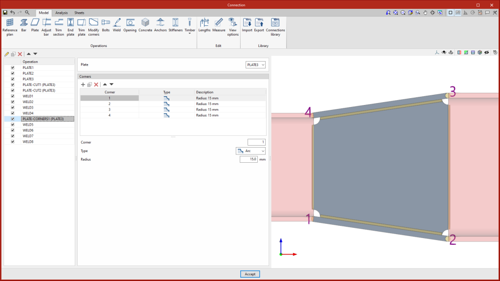
Up until the current version, connections could be analysed when the openings in plates or sections were internal, i.e. when they were completely contained in the plates. As of version 2023.d, openings can now intersect with the edges of the plates.

Improved clash detection

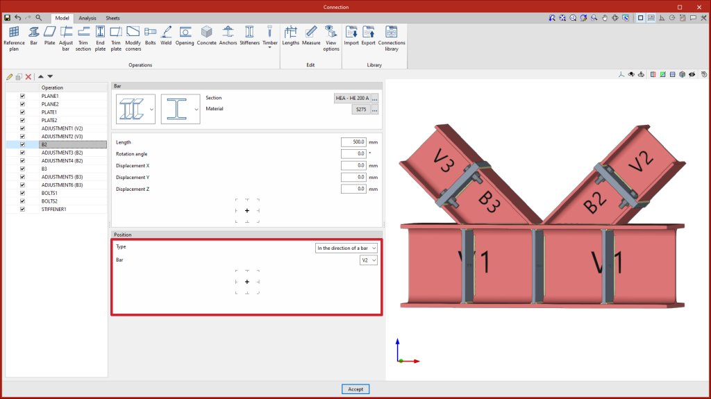
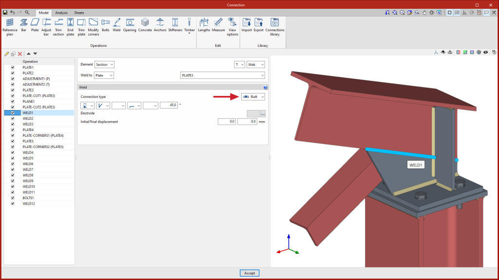
Clash detection between plates and sections has been improved. In previous versions, clashes between plates were detected as those that occurred in areas where an opening was placed. As an opening has been provided, the program no longer considers them as clashes because they do not represent a real situation. This allows users to model connections such as the one in the attached image.

Furthermore, as an improvement in clash detection, clashes between overlapping plates are detected.

SPIT brand chemical anchors for concrete fixings

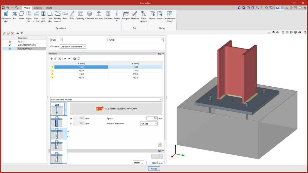
In version 2023.d of CYPE Connect and StruBIM Steel, SPIT brand post-installed chemical anchors can now be used as concrete fixings in baseplates. These elements are checked in accordance with the criteria of the EN 1992-4:2018 code, based on the data provided in the ETAs of these anchors (European Technical Assessment).

Font size

The "Font size" option has been added to the general configuration menu of the applications. This tool allows users to increase or decrease the basic size of the font used in the user interface of the programs. Thanks to this implementation, the accessibility of the applications has been improved while also ensuring the correct visibility of the content on devices with different screen resolutions.

To enter a "Basic size" the "Set custom font size" option must be checked. The size users can enter is the application's basic font size. Any other font sizes that may exist in the program's interface will be automatically modified proportionally according to the change in the basic size.

It is important to note that, as this is a common parameter, its modification will affect all installed CYPE tools.

Editing the levelling point

The editing of the levelling point has been added to the node bar definition and to the "Section" and "Plate" operations. This editing makes it easier to place sections and plates.

Analysing multiple connections

Two new options have been added to analyse multiple connections both simultaneously and automatically, so users no longer need to access the "Analysis" tab of each connection to click on the "Stress/Deformed shape" or "Rotational stiffness" buttons to carry out the analysis. These options are:

  • Analyse all the connections
    Using this option, the program will analyse all the connections
  • Analyse the selected connections
    This option allows users to select the connections they wish to analyse

Group of nodes

In version 2023.c, options have been added to manage groups of matching nodes. A group of nodes will be assigned the same connection.

The connection assigned to a group of nodes will read the bar forces of all the nodes in the group from the BIM project. The filtering of combinations carried out in "Generate from BIM model " is obtained from the sum of the combinations of all the nodes.

The options for managing these groups are:

  • Group
    Groups matching nodes. When a node is selected, all matching nodes will be highlighted in yellow.
  • Ungroup
    Ungroups previously grouped nodes.
  • Group automatically
    Automatically groups matching nodes.

Quick access to operations from the 3D view

Up until version 2023.b, the operations entered in the connection were accessed via the side list. In this version, quick access has also been provided by clicking on elements in the 3D view. Selecting elements in the 3D view will open the operation where the element is defined in the left panel.

Checking anchors

Version 2023.b implements the detailed checking of anchors in accordance with Eurocode EN 1992. Until version 2023.b, the analysis of the connection was carried out by considering the anchors positioned and the non-linear contact between steel and concrete, but without checking the resistance of the anchors.

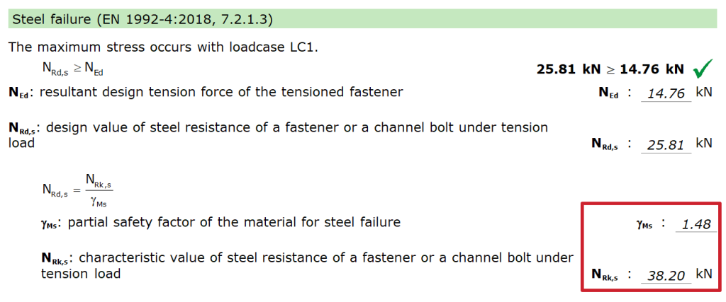
These new detailed checks can be consulted in the "Analysis" tab, as well as the checks already implemented for the rest of the elements. These checks can be for a single anchor as well as for the group.

In the project options, in the "Codes" dialogue box, the group of options relating to the concrete code for anchor testing has been implemented.

The "Anchors" operation includes the "Check anchors" option. When this option is activated, the program checks the anchors and also allows certain parameters and factors that must be taken into account in this check to be edited.

The connection summary list includes the resistance tables of the anchor group and the individual resistance of each anchor.

Implementation. EN 1992-4:2018 (EU International)

Eurocode 2 - Design of concrete structures - Part 4: Design of fastenings for use in concrete.

Implemented in CYPE Connect and StruBIM Steel for checking anchors in concrete.

Implementation. ACI 318M-19 (USA - International)

"Building Code Requirements for Structural Concrete".

Implemented in CYPE Connect and StruBIM Steel for checking anchors in concrete.

Analysing the rotational stiffness of connections

Version 2023.a of the "CYPE Connect" and "StruBIM Steel" programs includes the analysis of the rotational stiffness of the connections. With this analysis option, users can obtain as results the resistant moment, initial stiffness, secant stiffness and classification of the connection (rigid, semi-rigid or pinned) of the steel section.

To obtain the "Moment - Rotation" graph, the program carries out an iterative process by analysing the rotation in different load steps. The resistant moment is obtained when any element in the connection (plates, sections, welds or bolts) no longer complies, i.e. its demand capacity ratio is greater than 100%.

The "Analysis" tab includes the "Rotational stiffness" tool in the top toolbar. If the tool is selected, the rotational stiffness analysis is run.

Furthermore, the "Analysis" tool has been renamed. In previous versions, the "Analysis" button was used to run the stress and deformed shape analysis. This button will now be called "Stress / Deformed shape".

The results can be viewed on the right-hand side of the "Analysis" tab. The top drop-down menu allows users to choose the type of results to be displayed, "Stress/Deformed shape" or "Rotational stiffness". By selecting "Rotational stiffness" the program displays two tables and the "Moment - Rotation" graph.

The first table shows all the analysed bars with their secant stiffness and the connection classification in each plane. The second table shows the load cases analysed for the selected bar. Each load case will indicate the acting moment, the resistant moment, the secant stiffness and the initial stiffness.

The graph shows the curves for "Moment - Rotation", "Acting moment of the selected load case", "Resistant moment", "Ultimate stiffness for rigid connections (Sj,1)" and "Ultimate stiffness for pinned connections (Sj,2)".

As a result of implementing the rotational stiffness analysis, the following changes have been made to existing tools in the program:

  • Selecting bars and load cases
    Using the "Loads" button, the dialogue box is launched allowing users to select the bars from which the rotational stiffness of their connection is to be analysed. In the centre of this dialogue box, there are two tabs for defining the load tables, per load case. The "Rotational stiffness" tab requests a list of loads, the lengths of the elastic bar in the structural model (used to establish the limit stiffnesses of rigid or pinned connections) and the kb factor.
  • Generating from the BIM model
    By using the "Generate from BIM model" button, the dialogue box for applying filters and importing loads is launched. This version also includes options for importing loads for the rotational stiffness analysis. In addition to the loads, the elastic lengths of the bars in the structural model are also imported, these lengths are necessary in order to classify the connection correctly. Five options are provided for importing load cases depending on the forces:
    • Maximum moments, with simultaneous forces
      Imports load cases that have larger My or Mz moments, either positive or negative, as well as all other simultaneous forces.
    • Maximum moments, without the other forces
      For the maximum moment load cases, only the values of My and Mz are imported.
    • Maximum moments by plane, with simultaneous forces
      Imports load cases with maximum moments and their simultaneous forces per plane, i.e. creates load cases with forces per plane (XY and XZ).
    • All
      Imports all load cases.
    • None
      Does not import any load case.
  • Classifying the connection
    In order to classify the connection as rigid, semi-rigid or pinned, the limit stiffnesses for rigid and pinned connections are first established. Depending on the selected steel code, the initial stiffness or the sectional stiffness is compared with these limits.