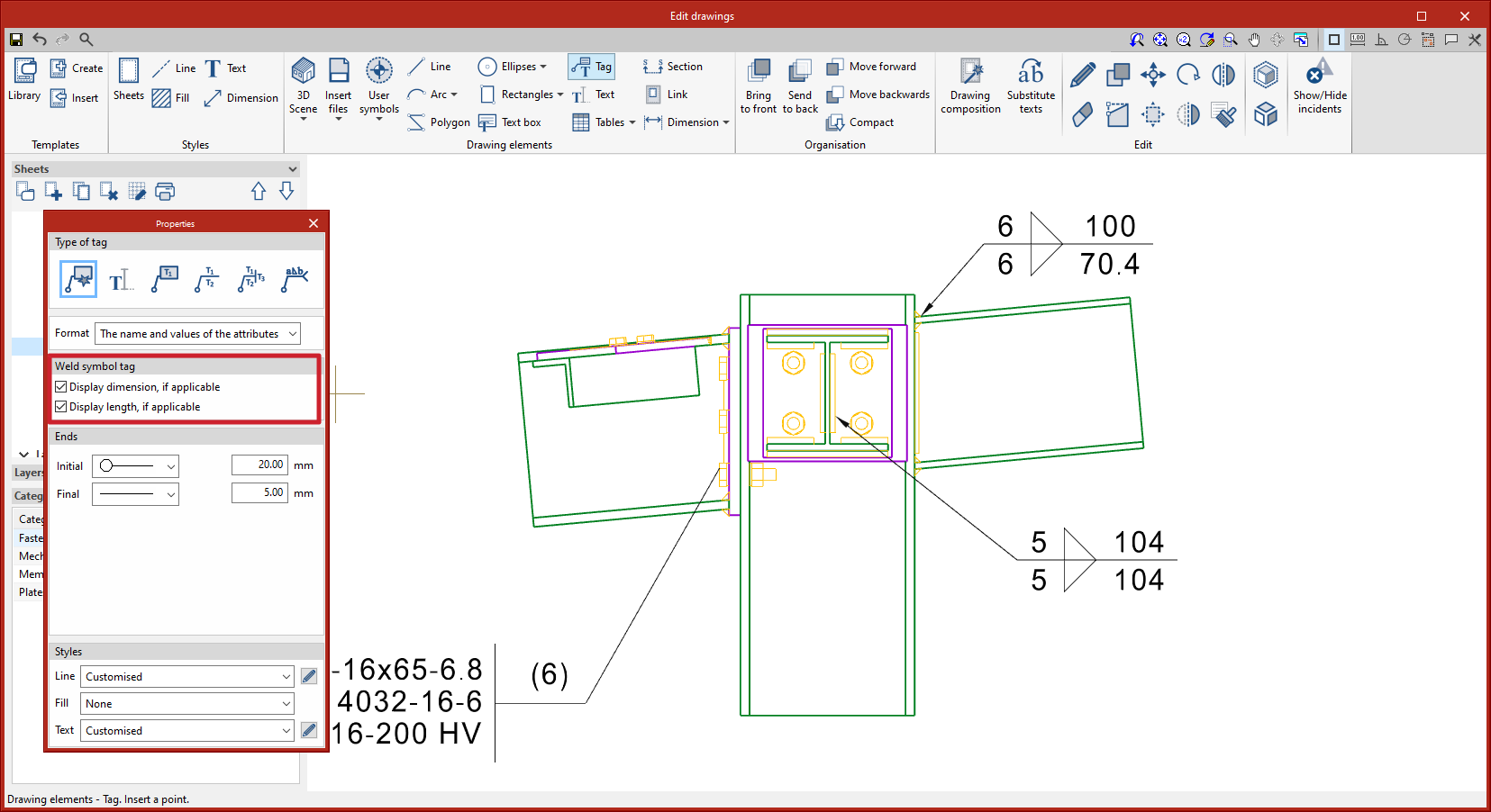
Weld tags display information about the welds in the model. Tags can be fully edited once entered, however, when entering tags, users are given the option to display or hide the dimensions and length, if applicable.


Weld tags display information about the welds in the model. Tags can be fully edited once entered, however, when entering tags, users are given the option to display or hide the dimensions and length, if applicable.
As of version 2023.d, in the notes section, the automatic weld tag now includes the reference of the electrode used as long as it has been defined in the operation where the weld is generated.

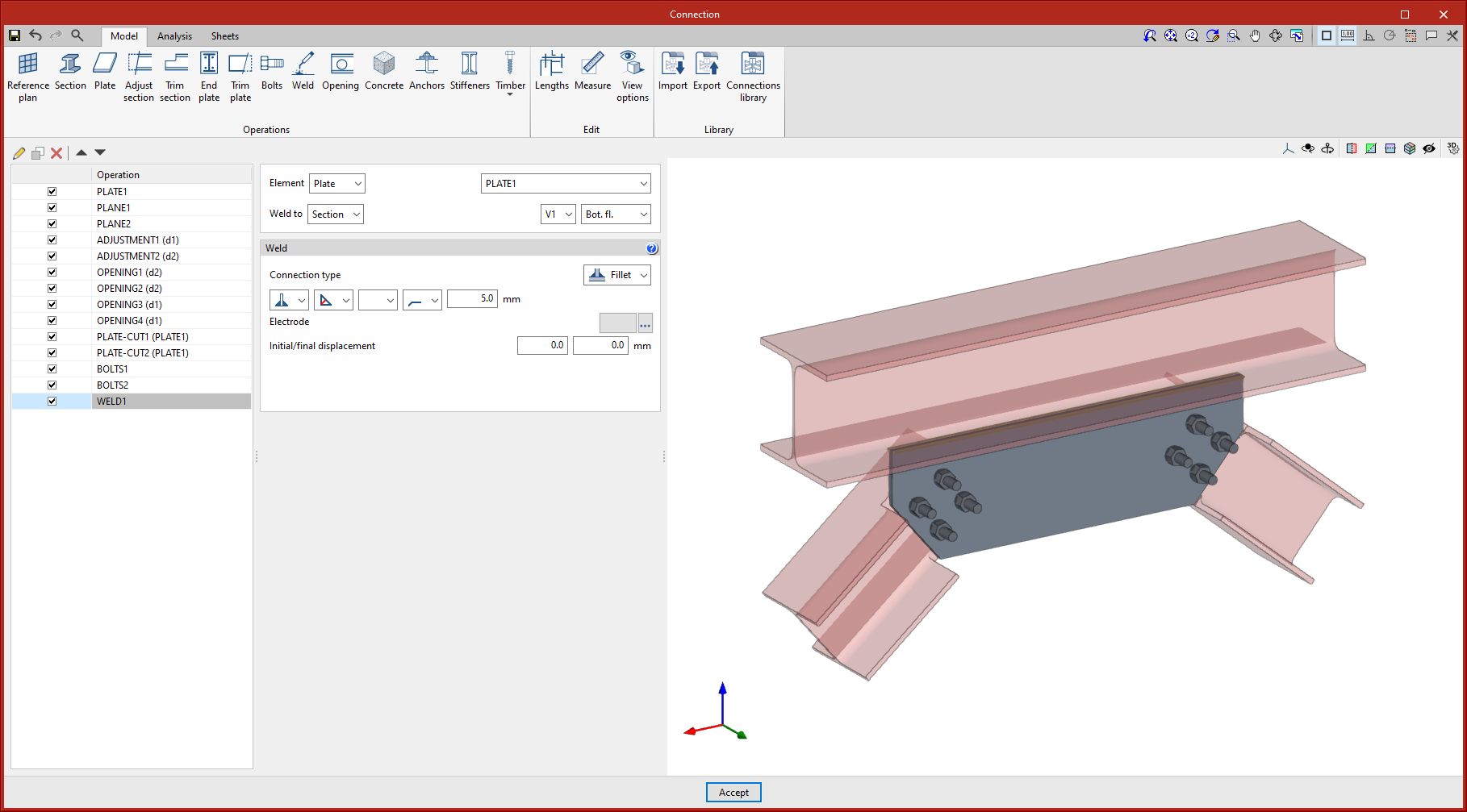
As of version 2023.d, welds can be applied to the internal contours of openings. This improvement, together with the improvements in clash detection and opening introduction, allows users to design and size connections with fitted plates, bars crossing openings, etc.
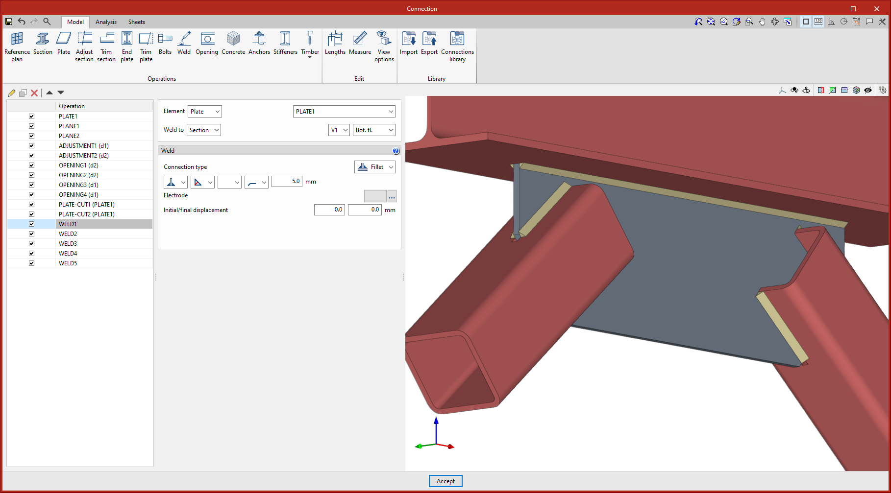
Up until the current version, connections could be analysed when the openings in plates or sections were internal, i.e. when they were completely contained in the plates. As of version 2023.d, openings can now intersect with the edges of the plates.
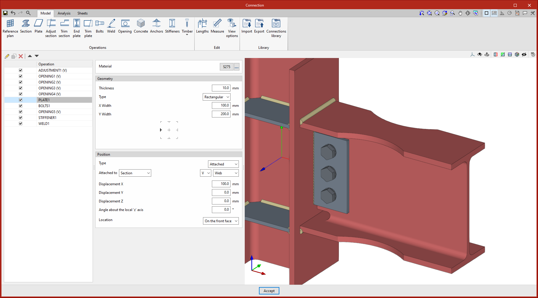
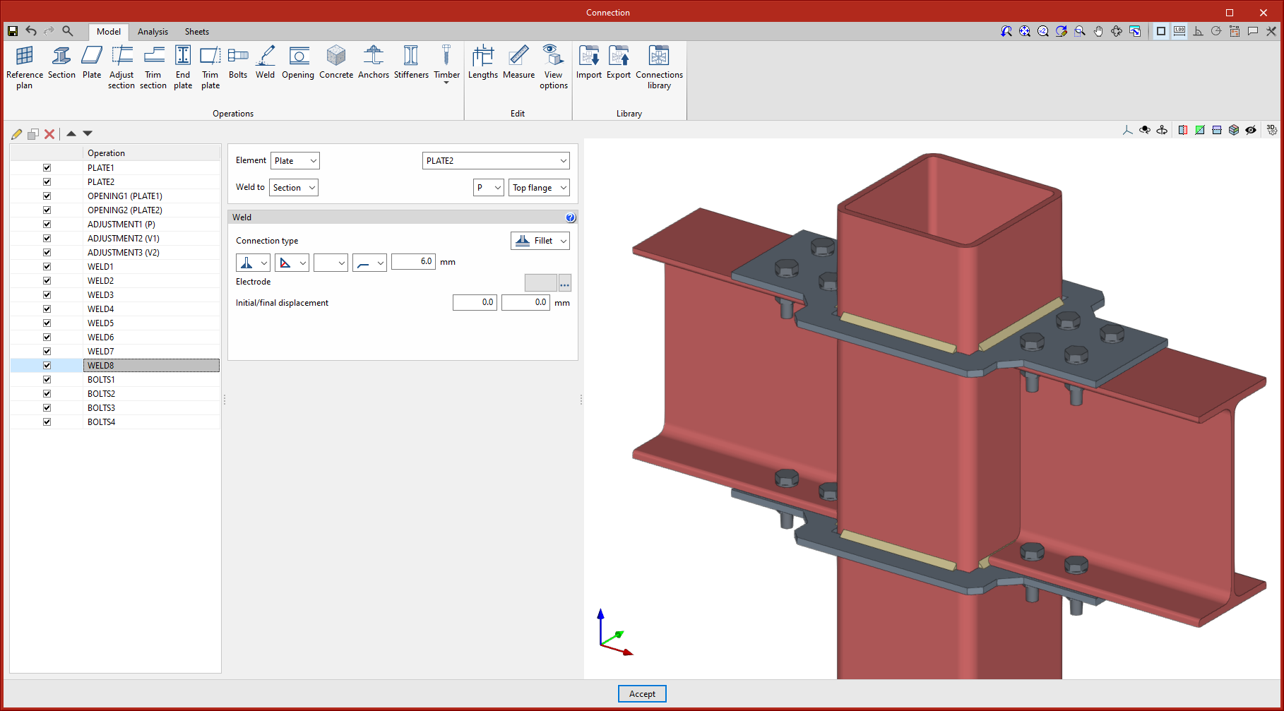
Clash detection between plates and sections has been improved. In previous versions, clashes between plates were detected as those that occurred in areas where an opening was placed. As an opening has been provided, the program no longer considers them as clashes because they do not represent a real situation. This allows users to model connections such as the one in the attached image.
Furthermore, as an improvement in clash detection, clashes between overlapping plates are detected.
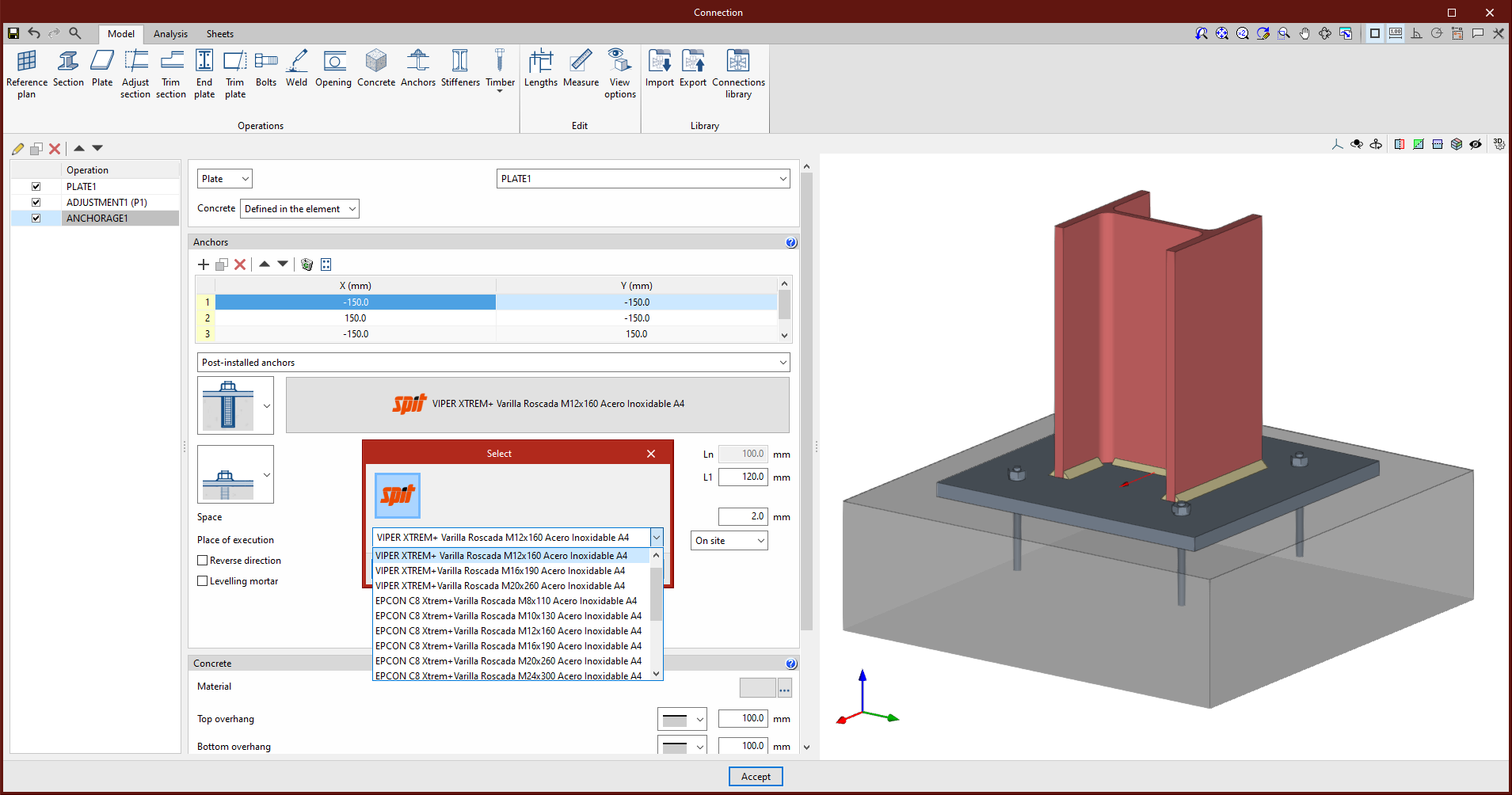
In version 2023.d of CYPE Connect and StruBIM Steel, SPIT brand post-installed chemical anchors can now be used as concrete fixings in baseplates. These elements are checked in accordance with the criteria of the EN 1992-4:2018 code, based on the data provided in the ETAs of these anchors (European Technical Assessment).
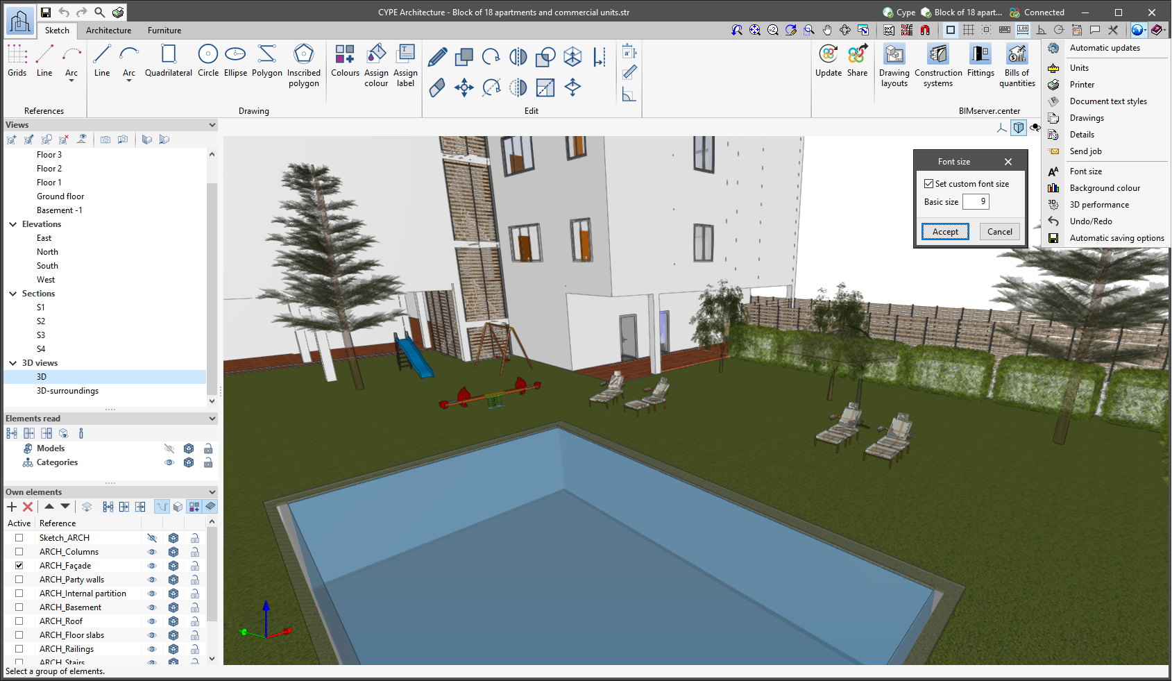
The "Font size" option has been added to the general configuration menu of the applications. This tool allows users to increase or decrease the basic size of the font used in the user interface of the programs. Thanks to this implementation, the accessibility of the applications has been improved while also ensuring the correct visibility of the content on devices with different screen resolutions.
To enter a "Basic size" the "Set custom font size" option must be checked. The size users can enter is the application's basic font size. Any other font sizes that may exist in the program's interface will be automatically modified proportionally according to the change in the basic size.
It is important to note that, as this is a common parameter, its modification will affect all installed CYPE tools.
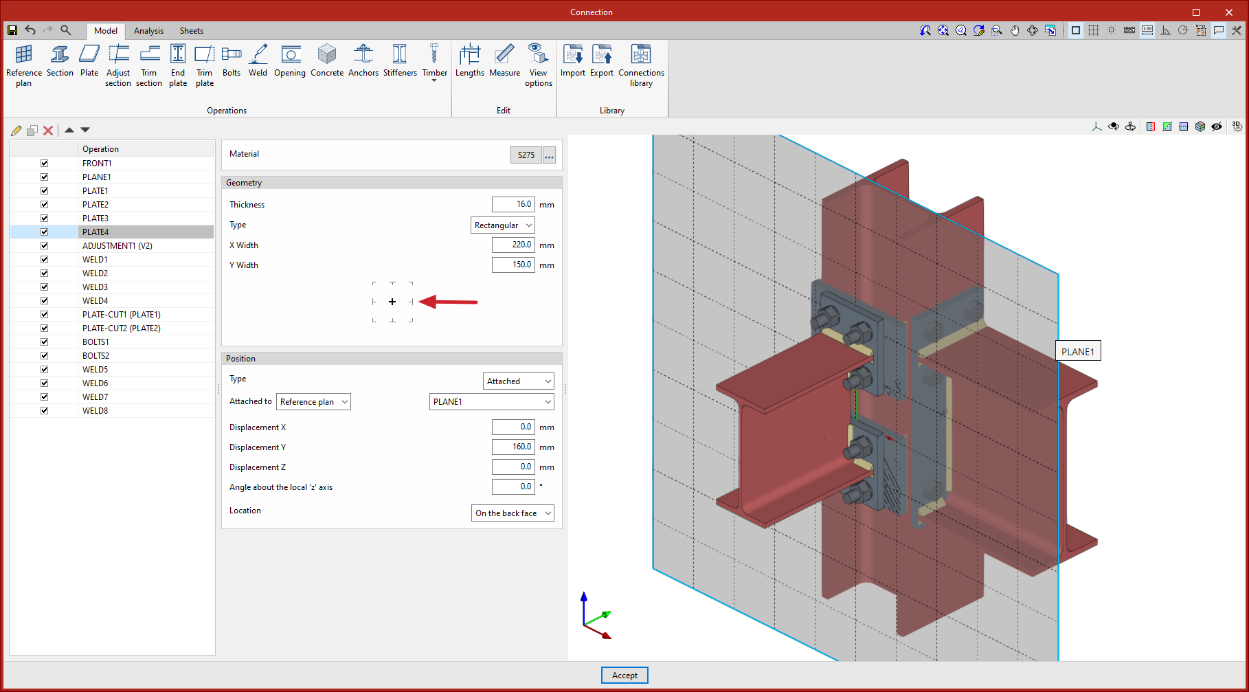
The editing of the levelling point has been added to the node bar definition and to the "Section" and "Plate" operations. This editing makes it easier to place sections and plates.
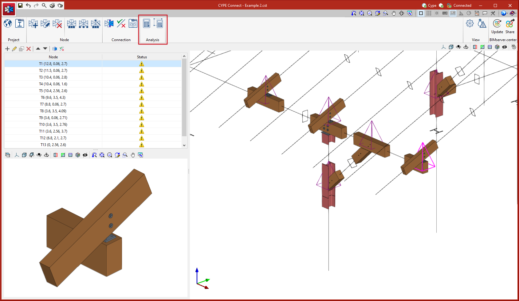
Two new options have been added to analyse multiple connections both simultaneously and automatically, so users no longer need to access the "Analysis" tab of each connection to click on the "Stress/Deformed shape" or "Rotational stiffness" buttons to carry out the analysis. These options are:
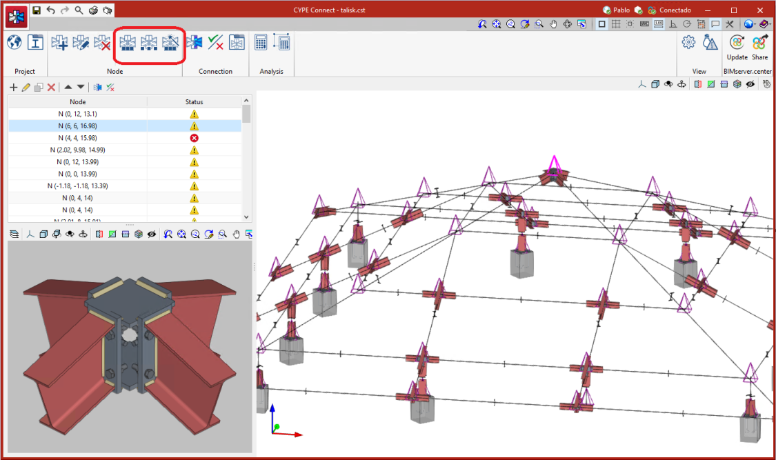
In version 2023.c, options have been added to manage groups of matching nodes. A group of nodes will be assigned the same connection.
The connection assigned to a group of nodes will read the bar forces of all the nodes in the group from the BIM project. The filtering of combinations carried out in "Generate from BIM model " is obtained from the sum of the combinations of all the nodes.
The options for managing these groups are:
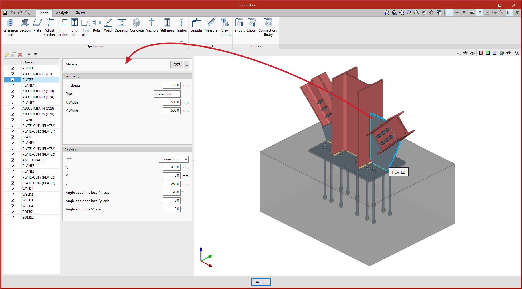
Up until version 2023.b, the operations entered in the connection were accessed via the side list. In this version, quick access has also been provided by clicking on elements in the 3D view. Selecting elements in the 3D view will open the operation where the element is defined in the left panel.
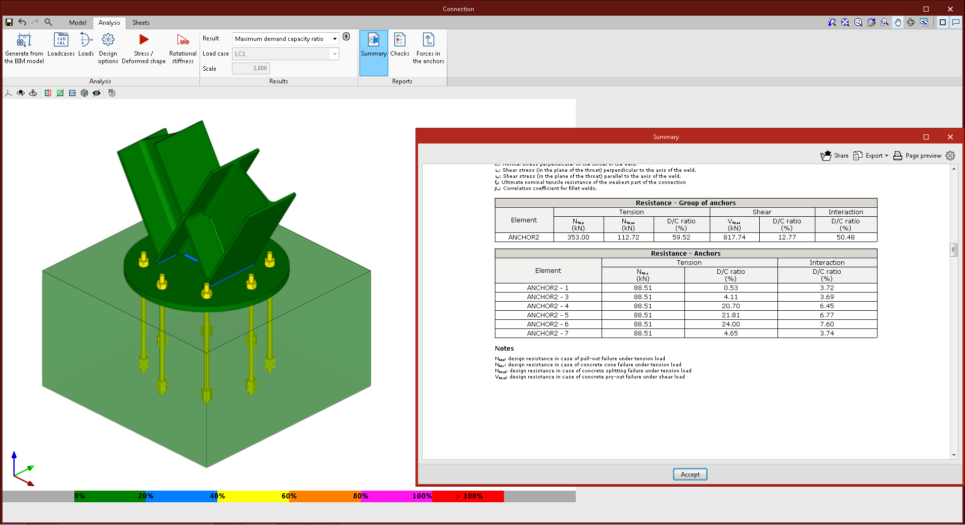
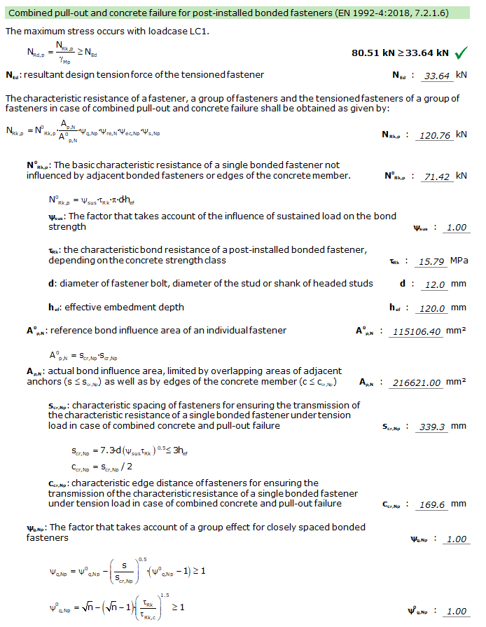
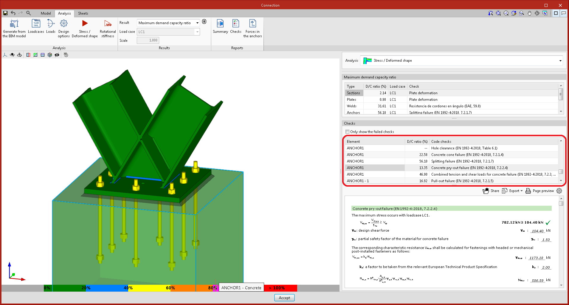
Version 2023.b implements the detailed checking of anchors in accordance with Eurocode EN 1992. Until version 2023.b, the analysis of the connection was carried out by considering the anchors positioned and the non-linear contact between steel and concrete, but without checking the resistance of the anchors.
These new detailed checks can be consulted in the "Analysis" tab, as well as the checks already implemented for the rest of the elements. These checks can be for a single anchor as well as for the group.
In the project options, in the "Codes" dialogue box, the group of options relating to the concrete code for anchor testing has been implemented.
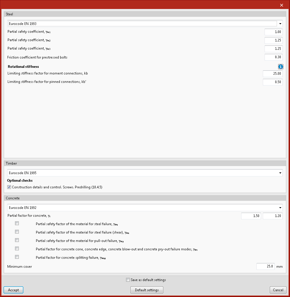
The "Anchors" operation includes the "Check anchors" option. When this option is activated, the program checks the anchors and also allows certain parameters and factors that must be taken into account in this check to be edited.

The connection summary list includes the resistance tables of the anchor group and the individual resistance of each anchor.