CYPE Mentor

Update history​​

StruBIM Steel

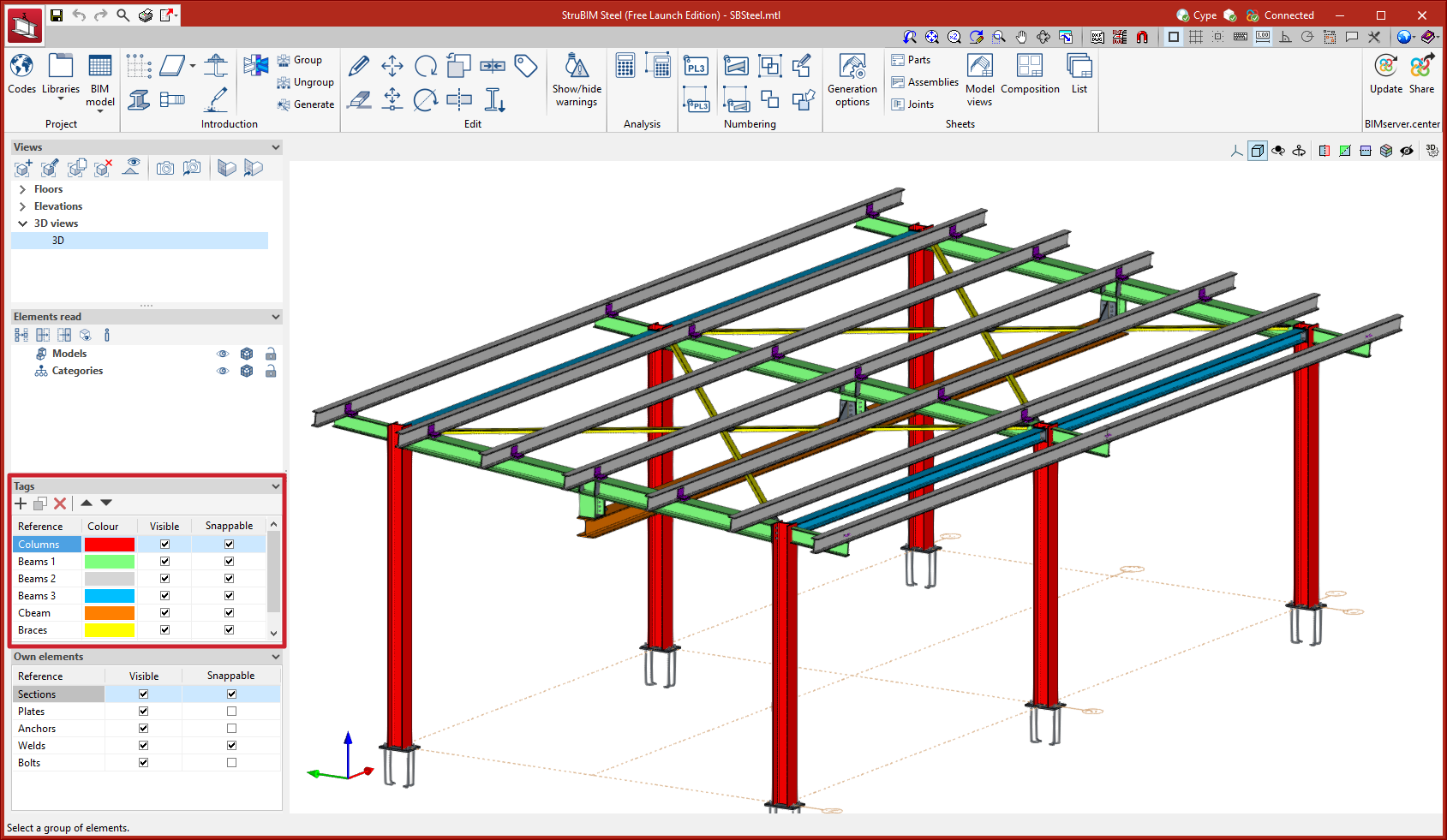
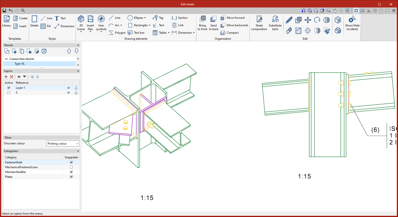
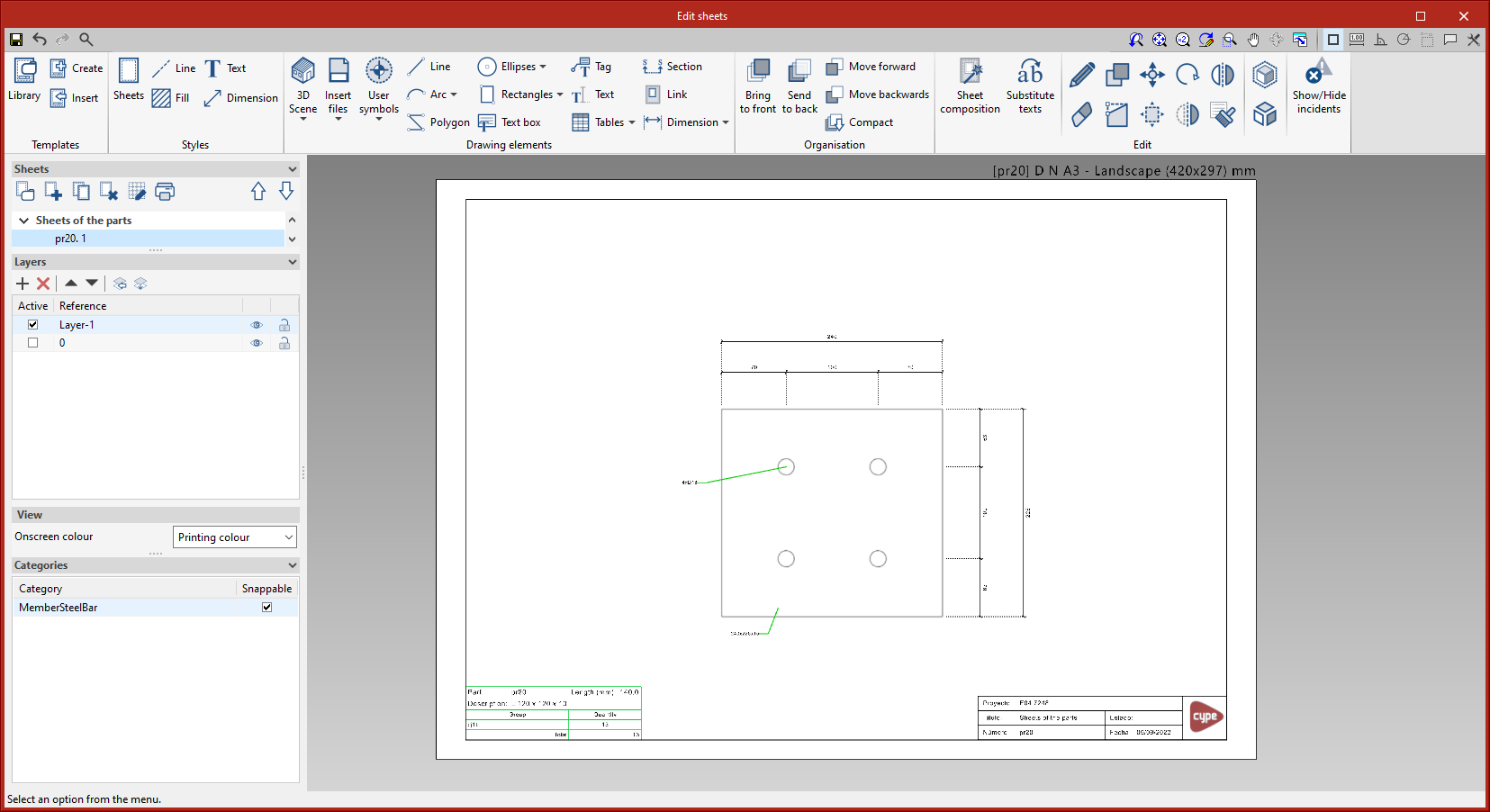
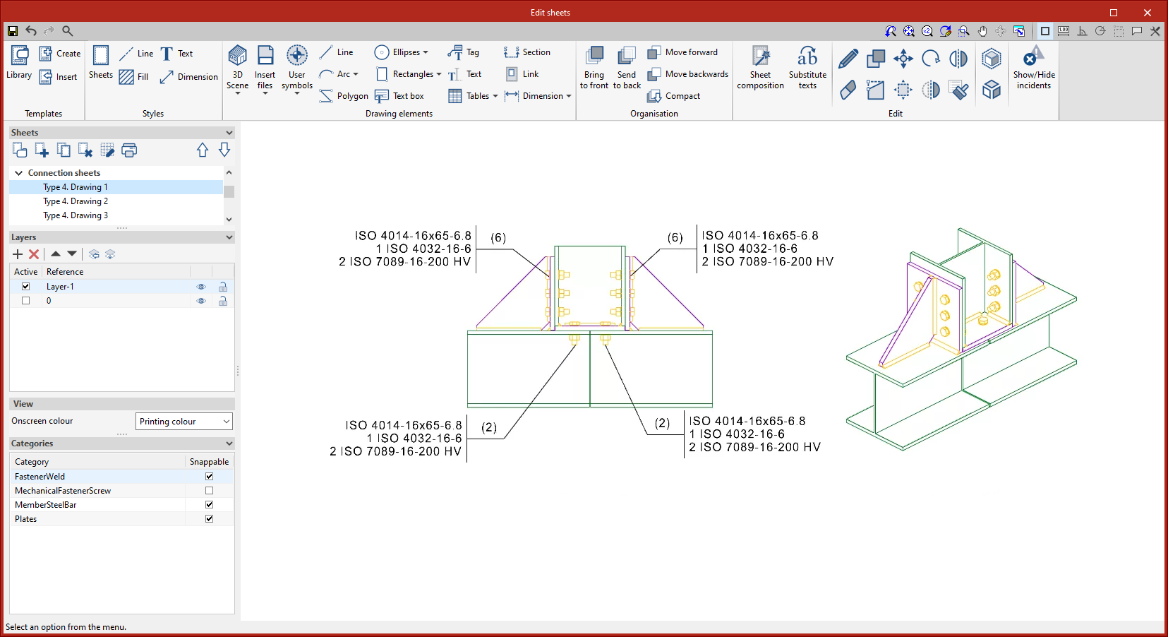
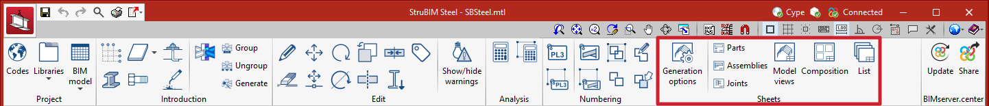
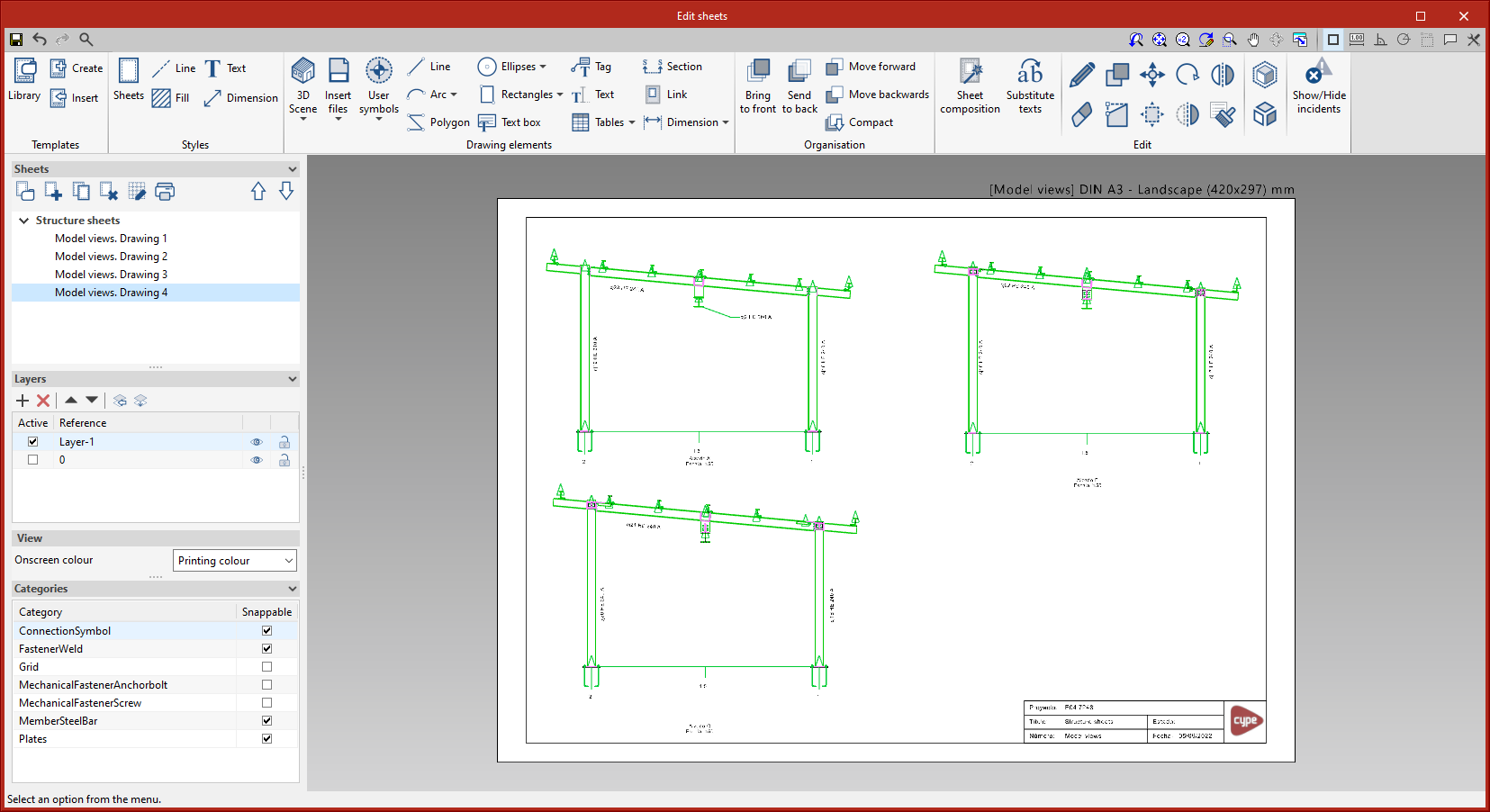
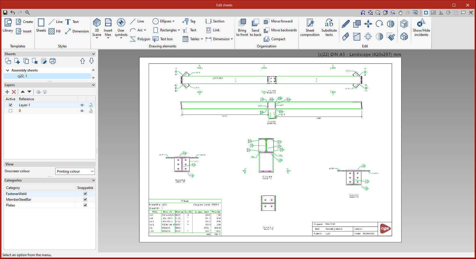
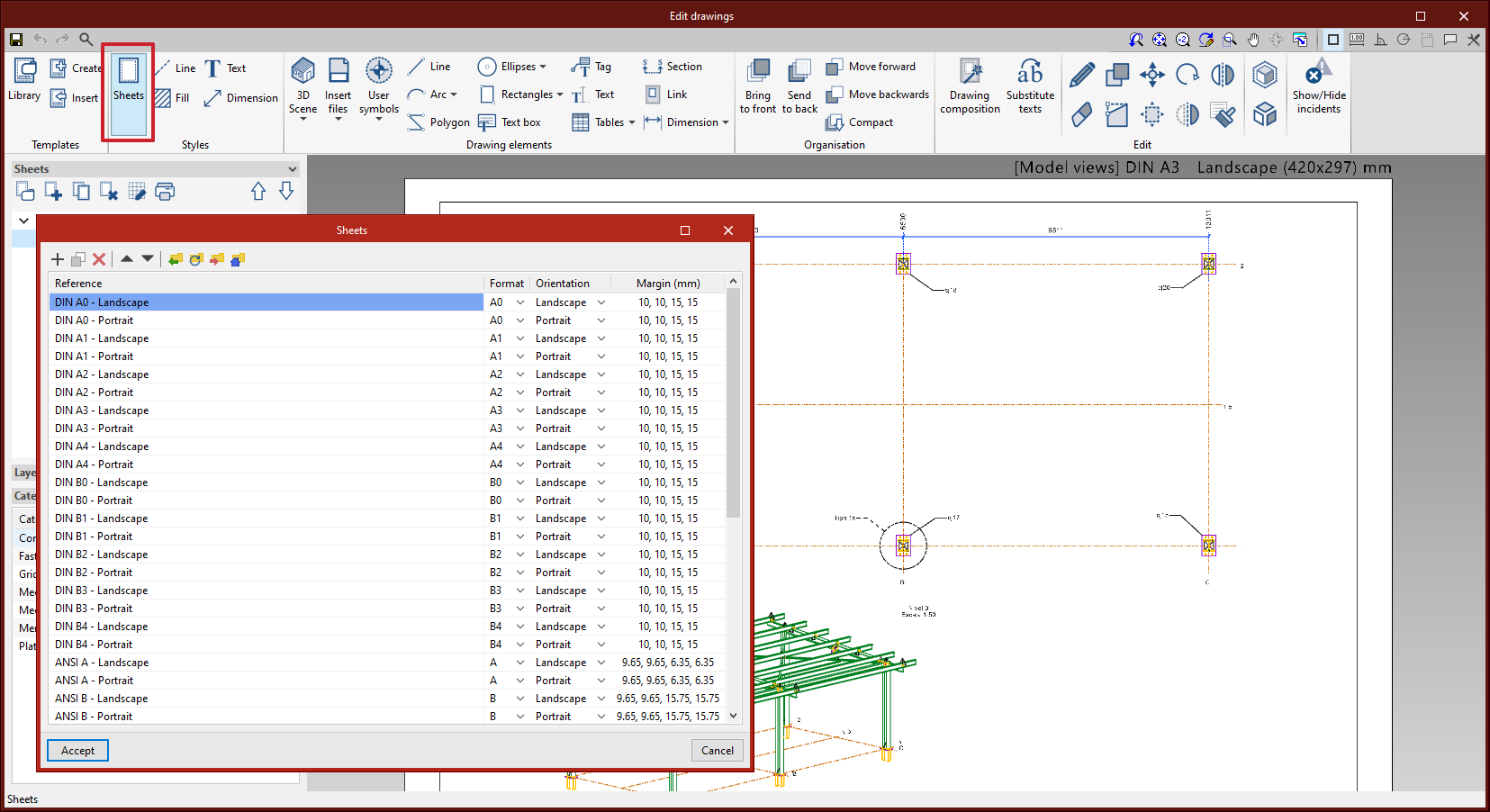
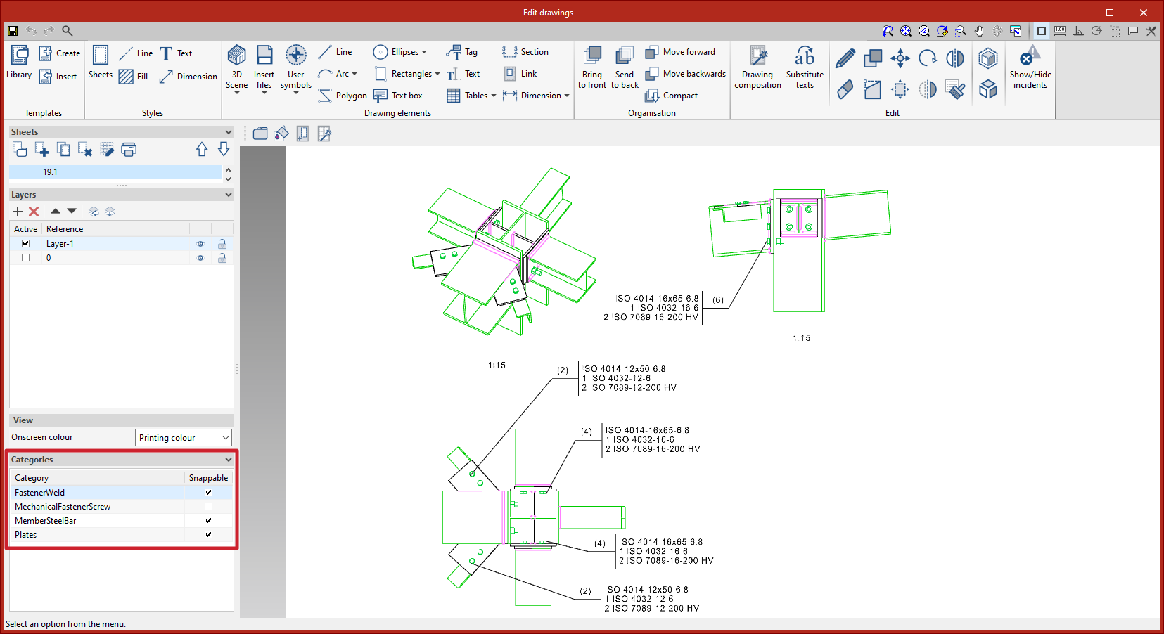
In previous versions, tag management was carried out by accessing a specific dialogue box from the options bar. As of version 2023.d, tag management is now located in the sidebar. This improvement allows quick access to commonly used commands such as activating or deactivating the view, creating new tags or deleting them and activating or deactivating snaps.

As of version 2023.d, the "Copy" tool will also copy the connections applied to the bars that are being copied. In previous versions, single elements (bars, plates, etc.) could be copied but, when this was done, the applied connections were not copied.

In version 2023.d, the tools required for generating graphical documents of the structure have been added. Using these tools, users will be able to create sheets of the parts (sections and plates), assembly sheets, joint sheets and sheets with the general model views. The "Generation options", "Parts", "Assemblies", "Joints", "Model views", "Composition" and "List" tools can be accessed from the "Sheets" menu.

These tools are included in the new StruBIM Steel module "Structural steel detailing drawings" and require the user license to have the corresponding permission for this module.

Generation options

The generation options are arranged in a dialogue box with four tabs ("Parts", "Assemblies", "Joints" and "Model views"), which have both common and specific options.

  • Sheet format (included in the four tabs)
    Allows the format of the new sheets to be selected. In "Type", users can select "Empty" together with the sheet format or "Based on template" together with the selection of one of the user-created templates and the layer. The template has a sheet format associated with it.
  • Organisation (included in the four tabs)
    Allows the group of sheets to be selected in which the newly created sheets will be generated.
  • Tables (“Parts” and “Assemblies” tabs)
    Allows the formatted text of the predefined tables in the tabs to be selected.
  • Drawing options (included in the four tabs)
    In this section, the option for displaying the chord radius of the sections can be found. This option is deactivated by default.
  • Tags of the “Assemblies” and “Model views” tabs
    Allows the information that will appear on the automatic tags in the main part of the assembly to be selected.
  • Number (“Joints” tab)
    Allows a prefix to be defined for numbering the joints.
  • Tags in the “Joints” tab
    Allows the information that will appear on the automatic tags of sections and plates to be selected.

All generation option settings can be saved in the user library. User libraries can be managed via the options buttons on the right-hand side of the "Generation options" dialogue box.

Parts

This tool provides access to the drawing and editing panel of the sheets of the parts of the selected element. In the sheets of the parts, only one element (section or plate) is shown and its geometry is graphically documented. In these sheets, the predefined table of uses of the part in assemblies can be entered.

Assemblies

This tool provides access to the drawing and editing panel of the assembly sheets of the selected element. The assembly sheets show all the elements (sections, plates, welds, bolts or anchors) that are part of the assembly being assembled in the workshop. In these sheets, the predefined table of the parts of the assembly can be entered.

Joints

This tool provides access to the drawing and editing panel of the joint sheets of the selected element.

Model views

This tool provides access to the drawing and editing panel of the model sheets, where the different views of the structure will be drawn.

Composition

From the "Composition" level, sheets can be created from other sheets, i.e. sheets made up of a composition of drawings from different elements.

The "Link" tool allows a reference to the content of one sheet to be inserted into another, while the "Sheet composition" tool generates a mosaic with the selected sheets.

List

In the "List of sheets" dialogue box, a list of all the sheets in the structure is displayed. From the list, the content of each sheet can be accessed by clicking on "Edit". The list allows the content to be filtered by category, content type and completion status. The columns "Finished", "Comments 1", "Comments 2" and "Comments 3" allow users to add notes or comments to each sheet, as well as to mark them as finished when they consider it so.

In version 2023.d, StruBIM Steel includes the new "Structural steel detailing drawings" module. This module allows the program to generate graphical documents of the structure. Using these tools, users will be able to create sheets of the parts (sections and plates), assembly sheets, joint sheets and sheets with the general model views. The “Generation options”, “Parts”, “Assemblies”, “Joints”, “Model views”, “Composition” and “List” tools can be accessed from the “Sheets” menu.

In order to work with this module, the user's license must have the corresponding permission.

More information on the features of this StruBIM Steel module is available at Structural steel detailing drawings.

As of version 2023.d, after scenes have been edited in the scenes library, only the affected scene views on the current sheet are regenerated.

Options that used to display submenus in previous versions now feature a pinned toolbar.

The editing of sheet styles has been added. From "Styles" > "Sheets" you can control the orientation and margins of each sheet format.

As of version 2023.d, scene views can include grids. These grids can be edited from the scenes library. In StruBIM Steel, scenes in model views will automatically include the grid if it has been defined in the model.

In version 2023.d, the editing of the line style for the outline of section fills in scene views has been added. From "3D Scene" > "Drawing attributes" > "Fill", users can access the dialogue box that allows them to edit the line style by category.

The following keyboard shortcuts have been added:

  • Alt+G: Modify geometry
  • Alt+P: Insert predefined views
  • Alt+I: Perpendicular dimension
  • Alt+Shift+I: Continuous dimension
  • Alt+Shift+A: Angle dimension

In version 2023.d, the management of categories marked as "Snappable" has been added to the sidebar. Each element in the 3D scenes belongs to a category.

This improvement is useful, for example, when tagging or dimensioning items to deactivate categories that don't need to be snapped. The sidebar location allows quick access to this commonly used tool.

In version 2023.d, the print management of elements according to their category has been added. From "3D Scene" > "Drawing attributes", users can access the dialogue box that allows them to select the categories to be printed ("Print by category" tab). Unchecked categories will be displayed on screen but will not be printed. This implementation is particularly relevant, for example, with connection symbols, which should be displayed on screen so they can be tagged, but not printed (see new feature "Connection symbols in drawing layouts").