Introduction
CYPEFIRE Hydraulic Systems is a program used to design and size hydraulic fire extinguishing networks using sprinklers, fire hose reels and fire hose reels, generic emitters and wet riser outlets.
The program can verify compliance with different predefined codes, as well as design systems using customised analysis configurations from other codes or technical standards.
Workflows supported by the program
As CYPEFIRE Hydraulic Systems is an Open BIM tool that is connected to the BIMserver.center platform, CYPEFIRE Hydraulic Systems offers different workflow options.
Data entry
Free definition
- Defining the elements in the model and their characteristics by means of free entry in CYPEFIRE Hydraulic Systems.
- System design in CYPEFIRE Hydraulic Systems based on DXF-DWG, DWF templates or images (.jpeg, .jpg, .bmp, .wmf).
Importing BIM models
If the CYPEFIRE Hydraulic Systems job is linked to a BIM project from the BIMserver.center platform, the following tasks can be carried out:
- Importing the model with the geometry of a building. This makes it possible to generate the layout of the building and to import the layout of the spaces and assign them a specific type, to subsequently enter the system elements (such as supply points and elements, water distribution networks and consumptions such as sprinklers, fire hose reels, emitters and wet riser outlets) based on this geometry. The following options are available:
- Importing models designed in CYPE Architecture.
- Importing models designed in IFC Builder.
- Importing models in IFC format (generated by CAD/BIM programs such as Allplan, ArchiCAD and others), uploaded to the BIMserver.center project via the web platform.
- Importing models designed in Autodesk Revit with the Open BIM - Revit Plugin.
- Importing the layout of the fire hose reels and the inlet and/or outlet openings of dry and wet risers from the model, if these elements are available. This will subsequently assist in the insertion of these elements using the program's own options.
- Importing sprinkler system requirements for spaces from the analysis results of the programs that define and validate fire protection systems:
- Importing sprinkler system requirements in spaces from models that have been analysed in CYPEFIRE.
Data output
- Exporting reports to HTML, DOCX, PDF, RTF and TXT formats.
- Exporting drawings to DXF, DWG and PDF formats.
- Exporting the bill of quantities to FIEBDC-3 format.
- Exporting the information generated with CYPEFIRE Hydraulic Systems to the BIMserver.center platform using IFC formats. This allows it to be viewed by authorised project participants.
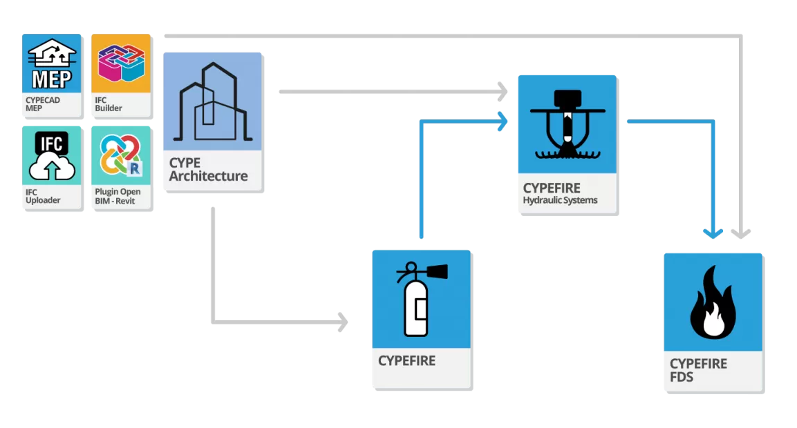
- CYPEFIRE FDS
Imports the layout of the CYPEFIRE Hydraulic Systems sprinklers.
- CYPEFIRE FDS
Work environment
The CYPEFIRE Hydraulic Systems interface has three tabs with different working environments: "Installation", "Diagrams" and "Bill of quantities". Both environments are similar to those in other CYPE tools and have a system of dockable windows that can be customised to adapt the workspace to the project's needs.
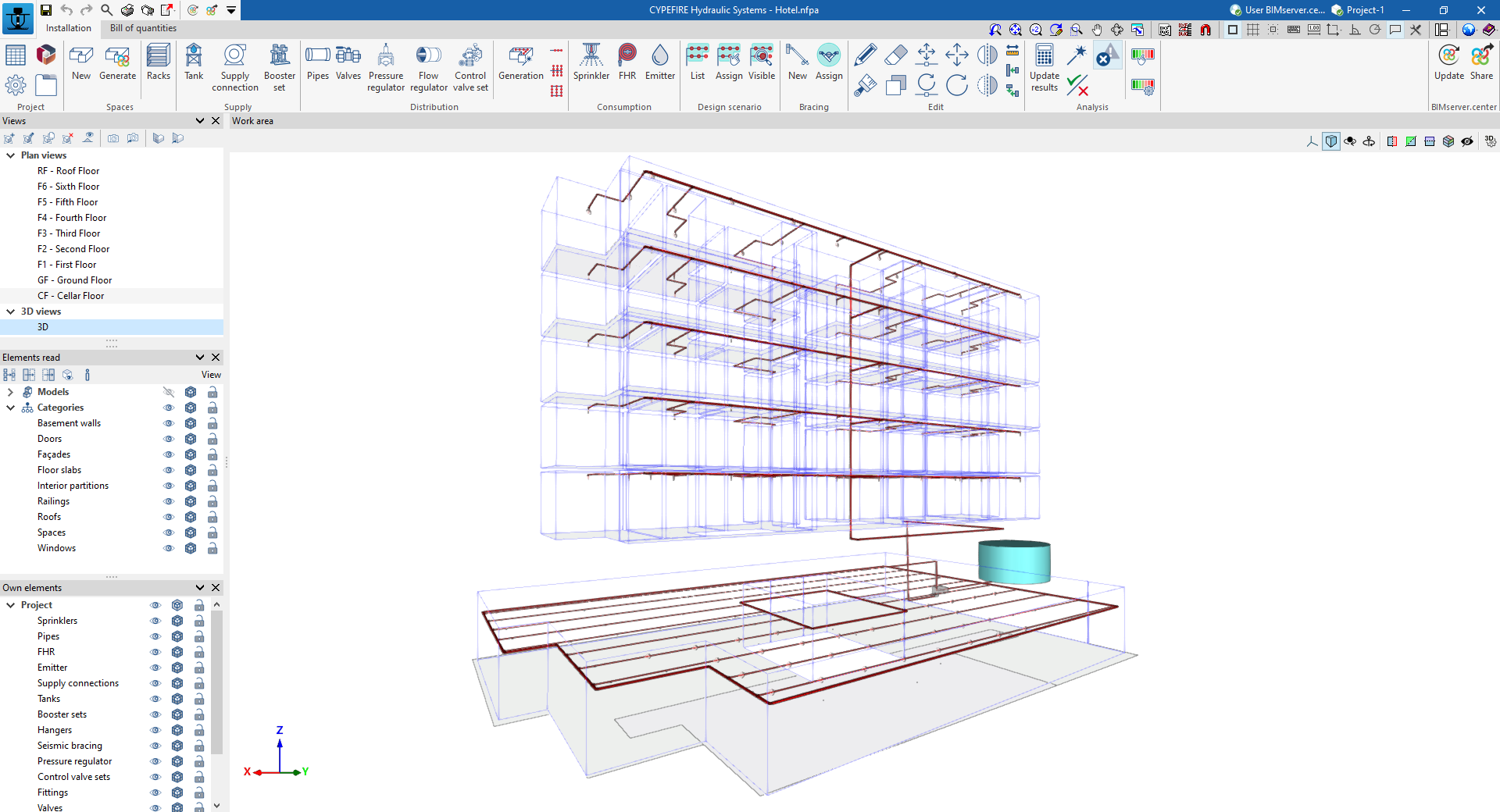
"Installation" tab
The tab activated by default when getting started is the "Installation" tab. This presents a work environment that allows the installation's design to be carried out quickly and easily, both in a 3D view and in any type of 2D view (such as floor plans and elevations). This way, the installation elements can be entered using the most appropriate view at any given moment.
The tab shows:
- A top toolbar containing the tools for: managing the general characteristics of the project; entering and generating spaces; entering the supply points, the elements of the water distribution network and the consumptions (sprinklers, fire hose reels, emitters and wet riser outlets); defining the design loadcases; entering the seismic bracing; using the editing tools; and carrying out the analysis, checking and sizing of the installation.
- The modelling area, on the right side of the screen, where all the project elements are entered, edited and displayed.
- On the left-hand side, several panels with tools for defining the project views and for managing the visibility of the elements read and the own elements.
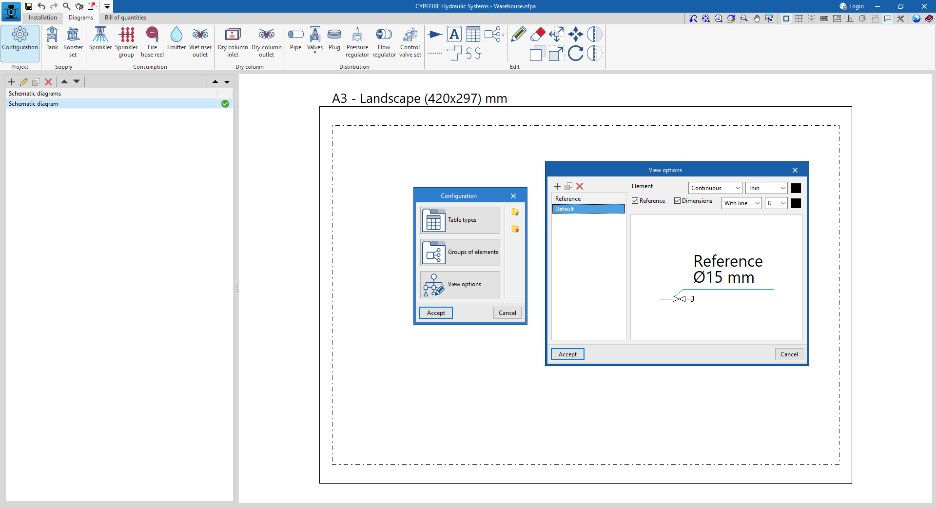
"Diagrams" tab
The "Diagrams" tab provides a working environment that can be used to compose fire extinguishing system diagrams on sheets in the desired formats.
This tab displays:
- A top toolbar containing the tools for entering the elements that make up the fire extinguishing system and configuring the display options.
- The workspace, on the right-hand side of the screen, where the system diagrams are entered, edited and displayed.
- On the left-hand side, a navigation panel between the different diagrams created, which are composed of editable format and scale sheets.
"Bill of quantities" tab
On the other hand, the "Bill of quantities" tab is used to manage the bill of quantities of the elements in the installation, and displays the following:
- A top toolbar where the tools for creating and editing the bill of quantities are located, as well as those for managing and creating reports.
- A graphic window with its own toolbar, located on the right-hand side, in which the different elements of the job can be displayed.
- On the left-hand side, is a specific area for structuring the bill of quantities.

Data input and output sequence for the design and analysis of fire extinguishing systems
The fire extinguishing system can be defined and analysed in the program using the following input and output sequence:
- Creating a new job (from "File", "New").
- (Optional) Linking to BIMserver.center, defining standards and reading and classifying spaces read from the BIM model, as well as the position of the fire hose reels and the inlet and/or outlet openings of dry and wet risers and their positions.
- Review of code configuration and general options and data (from "Project", "Code configuration"/"General options"/"General data").
- Importing manufacturers' catalogues (from "Project", "Catalogue management").
- (Optional) If they have not been read and generated from the BIM model, the spaces must be entered manually (from "Spaces", "New").
- Arranging the elements of the system supply ("Supply" group) in the work area. This can be done in two ways:
- Entering a tank and a booster set.
- Entering a connection to the public network.
- Arranging consumptions (sprinklers, fire hose reels, emitters, and/or wet riser outlets) and pipes in the work area. This can be done in several ways:
- Automatic generation (from the "Distribution", "Generation / Branch / Cross main with branch lines / Grid system").
- Manual entry (group "Consumption" and "Distribution", "Pipes").
- (Optional) Entering other elements in the "Work area":
- Entering racks (from "Spaces", "Racks").
- Entering valves, pressure and flow regulators or control valve sets ("Distribution" group).
- Entering seismic bracings and assigning of pipes in their zone of influence ("Bracings" group).
- Entering a dry riser installation (options in the "Dry riser" group).
- Defining and assigning design scenarios to indicate the consumptions that are active in them.
- Defining design scenarios (from "Design scenarios", "List").
- Assigning scenarios consumptions (from "Design scenarios", "Assign").
- Analysing or designing the system, displaying the results on the screen and in the results reports ("Analysis" group).
- (Optional) Creating installation diagrams ("Diagrams" tab).
- (Optional) Creating and managing the bill of quantities ("Bill of quantities" tab).
- Obtaining reports and drawings (from "Results", "Reports"; and from "File", "Drawings").
- Exporting to BIMserver.center (from "BIMserver.center", "Share").
Examples of fire extinguishing system diagrams
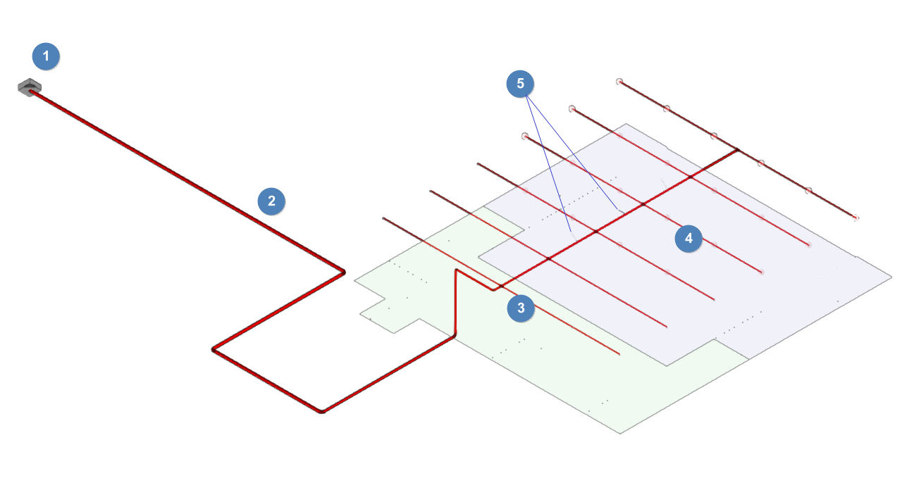
Below are several diagrams of fire extinguishing systems that can be developed in the program, indicating the layout of the elements, as well as the options that allow them to be entered into the model:
Installation of sprinklers with a supply connection
- Supply connection (from "Supply", "Connection").
- Pipes (from "Distribution", "Pipes" [manual entry]; from "Distribution", "Generation / Branch / Cross main with branch lines / Grid system" [assisted entry].
- Sprinklers (from "Consumption", "Sprinklers" [manual input]; from "Distribution", "Generation / Branch / Cross main with branch lines / Grid system" [assisted entry].
- Active sprinklers (from "Design scenarios", "Assign").
- Seismic bracings (from "Bracings", "New") [in case of seismic analysis].
Sprinkler installation with tank and pressure boosting system
- Tank (from "Supply", "Tank").
- Booster set (from "Supply", "Booster set").
- Pipes (from "Distribution", "Pipes" [manual entry]; from "Distribution", "Generation / Branch / Cross main with branch lines / Grid system" [assisted entry].
- Sprinklers (from "Consumption", "Sprinklers" [manual input]; from "Distribution", "Generation / Branch / Cross main with branch lines / Grid system" [assisted entry].
- Active sprinklers (from "Design scenarios", "Assign").

Creating a new job, linking to a project and importing data
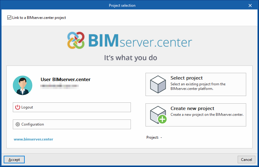
When starting the program and clicking on "New", the program offers users the possibility to create a "New job", which can then be integrated into an existing project in BIMserver.center.
This is done in the "Project selection" window. On the left-hand side, you can log in with a BIMserver.center account.
- On the left-hand side, users can log in with a BIMserver.center account.
- On the right-hand side, the "Select project" option is used to choose an existing project. There is also the possibility to "Create a new project". In this case, the created project will be visible from BIMserver.centre from that moment on.
- The project can also be starting without being linked to the BIMserver.center platform. To do this, simply uncheck the box at the top left, "Link to a BIMserver.center project".
Once the new job has been created, the program interface is accessed, where the graphic window showing the model or models that have been imported stands out. At any time during the project, files can be shared or imported via the "BIMserver.center" group on the top right-hand side.
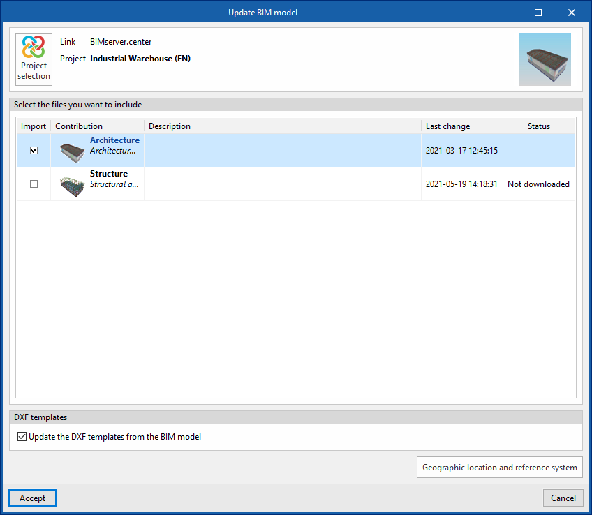
Importing BIM models
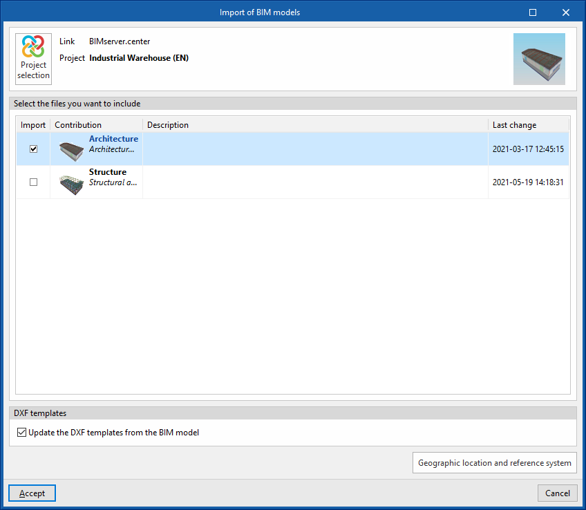
When creating a new job and selecting a project hosted on the BIMserver.center platform from "Select project", the "Import BIM models" window appears, which shows the files contained in that project in IFC format.
The program is able to include one or more of the existing models in the project. To do this, check the "Import" box and accept it.
When accessing the interface, the graphic window will display the imported models. Also, if they contain this information, the plan views needed to develop the system model will be imported and created.
| Note: |
|---|
| To load a different policy configuration later, or to consult or customise it, access the "Code configuration" in the "Project" group, in the top toolbar of the "Installation" tab. |
Configuration wizard: selecting standards, downloading catalogues and classifying spaces
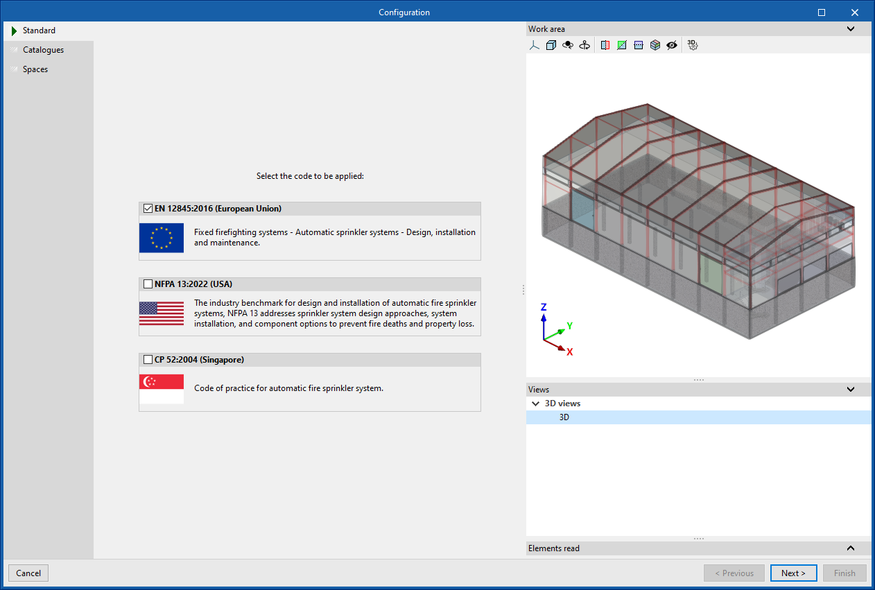
The program then opens the "Configuration" wizard, which consists of the following steps:
- In the first step, the applicable codes can be selected from those available for different countries and regions. The checks defined in the standard are then automatically imported.
| Note: |
|---|
| If you wish to subsequently load a different code configuration, consult it or customise it, you must access the "Code configuration" in the "Project" group, in the top toolbar of the "Installation" tab. |
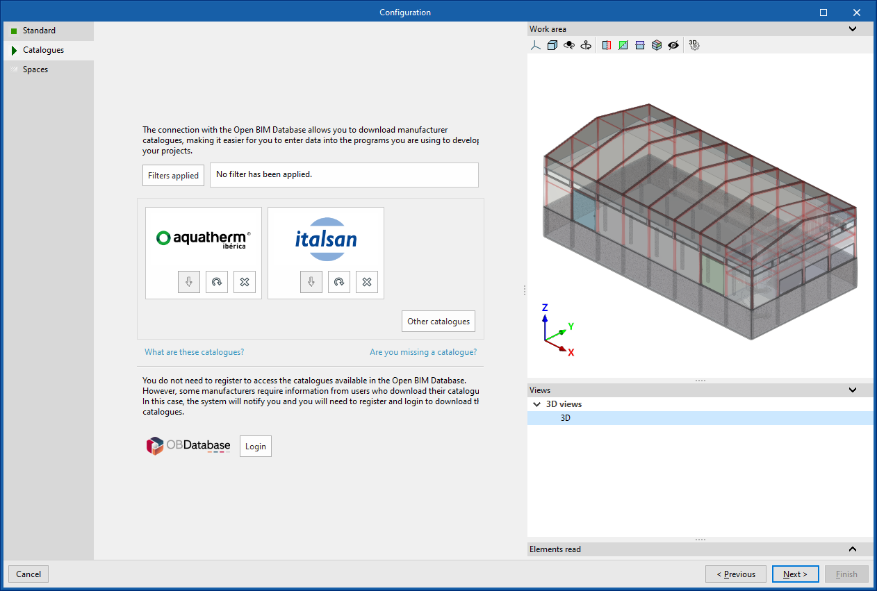
- In the next step, the connection to the Open BIM Database can be established in order to download and manage manufacturer catalogues. These catalogues will be available at the time of entering the elements in the system.
| Note: |
|---|
| To manage the job's catalogues at any time, use the "Catalogue management" option in the "Project" group in the top toolbar of the "Installation" tab. |
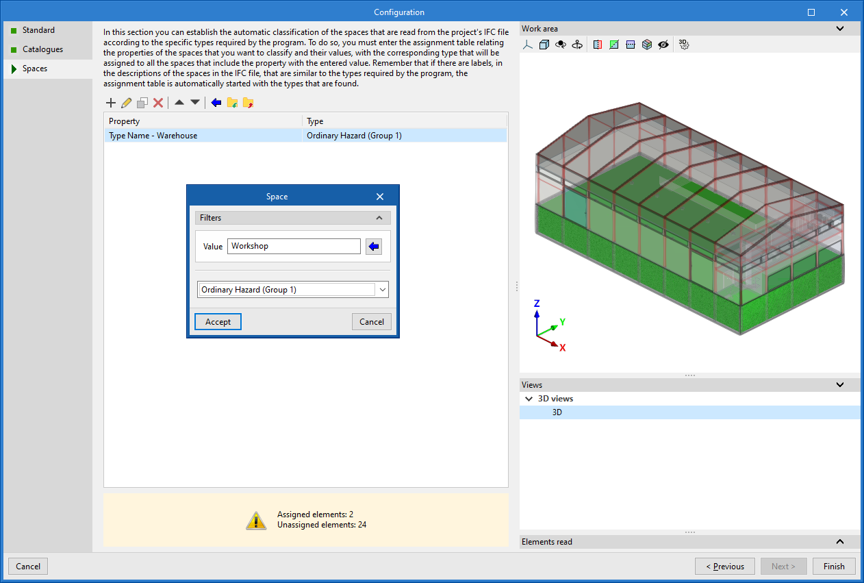
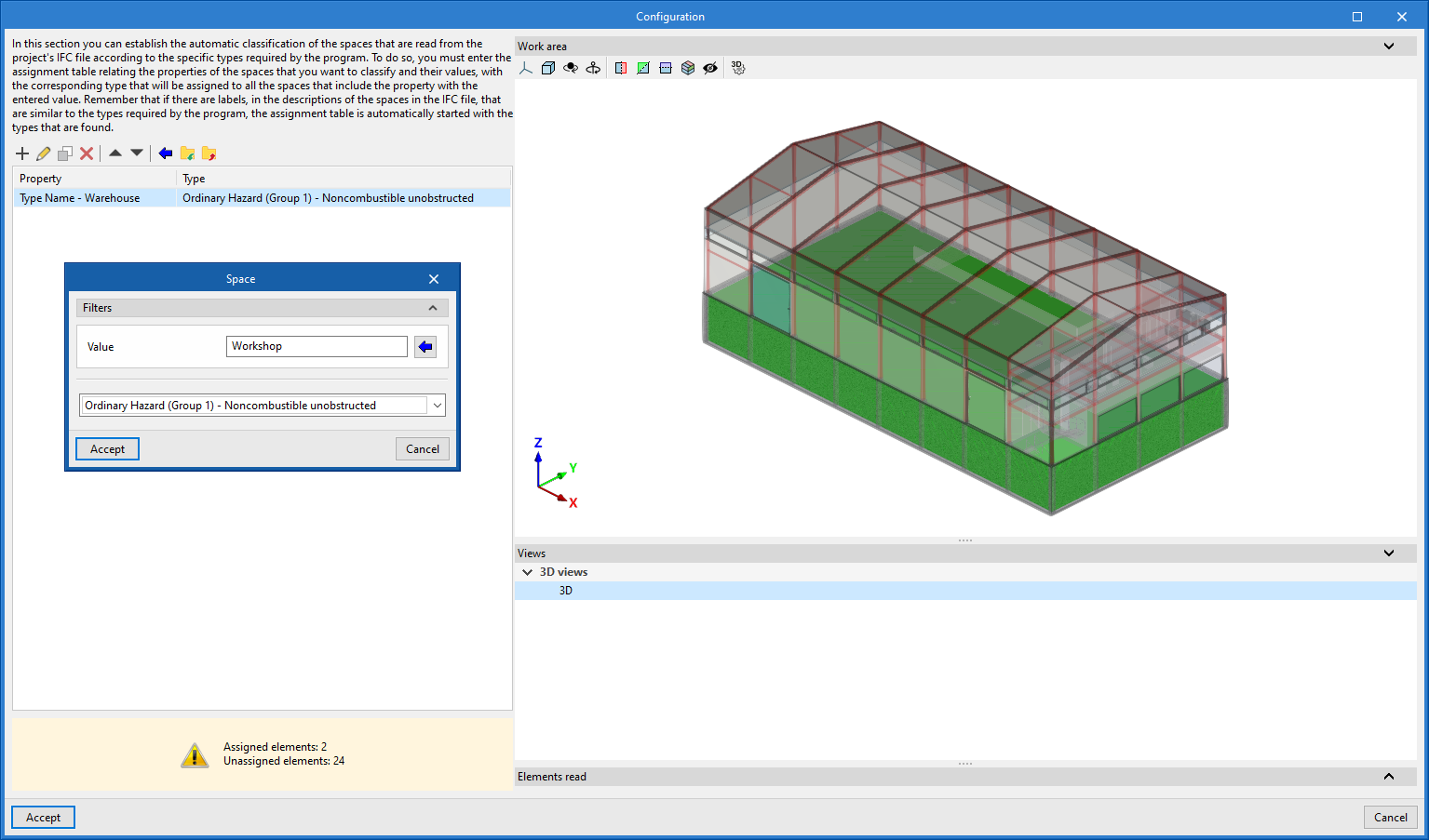
- Finally, in the last step you can set the automatic classification of the spaces read from the project’s IFC file according to the specific typologies required by the program.
To do this, entries must be added to the assignment table manually (using the "Add" button) or via the wizard.
In each entry, the spaces to be classified are filtered by specifying the values of their properties (in the "Value" parameter), and the room typology defined by the program that you wish to assign to them is selected (by activating the "Requires sprinkler system" box and choosing a specific room typology). In addition, you can indicate whether "Sprinkler protection above the false ceiling" will be included by activating the corresponding box and entering the "Air void height" value (in which case the "2 layers" column will be marked in the list).
You can also use the wizard in the upper toolbar to perform a joint import of all the spaces read in the IFC file based on the desired property, thereby generating one table entry for each group of spaces with the same property (which can then be adjusted by clicking the "Edit" option).
On the right, the program allows you to view the layout of the selected spaces in the model.
Any spaces that you do not intend to calculate must be removed from this classification table.
The program will assign the selected space type to all the rooms read from the IFC file that have the value indicated in the property shown in the wizard, and it will generate the geometry of the zones, adding them to the model view.
| Note: |
|---|
| If the spaces read from the BIM model need to be re-sorted, the "Update" option in the "BIMserver.center" group, also in the top toolbar of the "Installation" tab, can be used. In addition, to generate them again in the model, use the "Generate" option in the "Spaces" group. |
Additionally, it will read the position of the fire hose cabinets and the inlet and/or outlet points of dry and wet risers defined in the IFC file, from which the corresponding elements can be introduced using the program’s own options. It will also read the geometry of model elements such as beams and columns, allowing a collision analysis with the installation elements during the calculation.
Management of the elements entered in the project
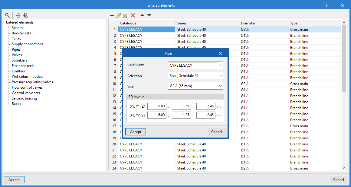
Within the "Installation" tab, in the "Project" group of the main toolbar, there is an option to manage the elements inserted in the project:

Elements entered
The data of each of the elements entered in the model can be consulted and edited, such as their reference, their 3D layout, their type and their characteristics, in the following tables:
- Spaces
- Booster sets
- Tanks
- Supply connections
- Pipes
- Valves
- Sprinklers
- Fire hose reels
- Emitters
- Wet riser outlets
- Pressure regulating valves
- Flow control valves
- Control valve sets
- Seismic bracing
- Racks
Defining the project's general options
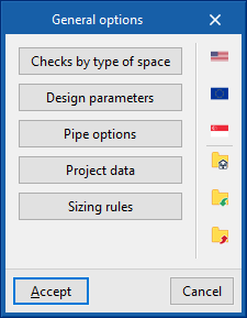
Within the "Installation" tab, in the "Project" group of the main toolbar, the "General options" of the project can be defined:

The following options are available:
- Checks by type of space
- Checks to be carried out on the fire hose reels
- Design parameters
- Pipe options
- Valves
- Project data
- Sizing rules
- Prescription options
By using the configuration import options available on the right-hand side of the "General options" panel, this data can be generated automatically for different national and international codes, such as the following:
 NFPA 13 and NFPA 14 (United States)
National Fire Protection Association. Standard for the Installation of Sprinkler Systems / Standard for the Installation of Standpipe and Hose Systems- EN 12845:2016 (European Union)
Fixed firefighting systems - Automatic sprinkler systems - Design, installation and maintenance - CP 52:2004 (Singapur)
Singapore Standard - Code of practice for automatic fire sprinkler system
For systems in the rest of the world or for specific analyses, the checks can be entered and configured manually in a customised way.
The other options in the right-hand column can be used to import and export the complete configuration of the "General options" panel to files on disk, as well as to select a file with initial values for the creation of a new job.
Details of the above-mentioned features are given below.
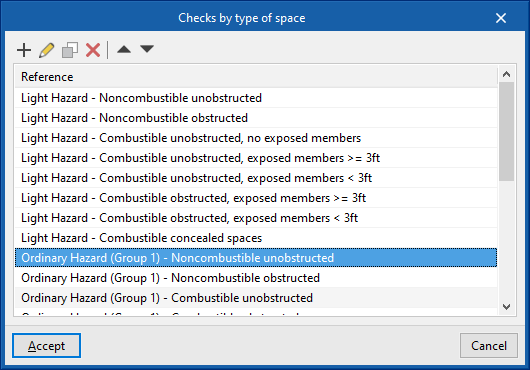
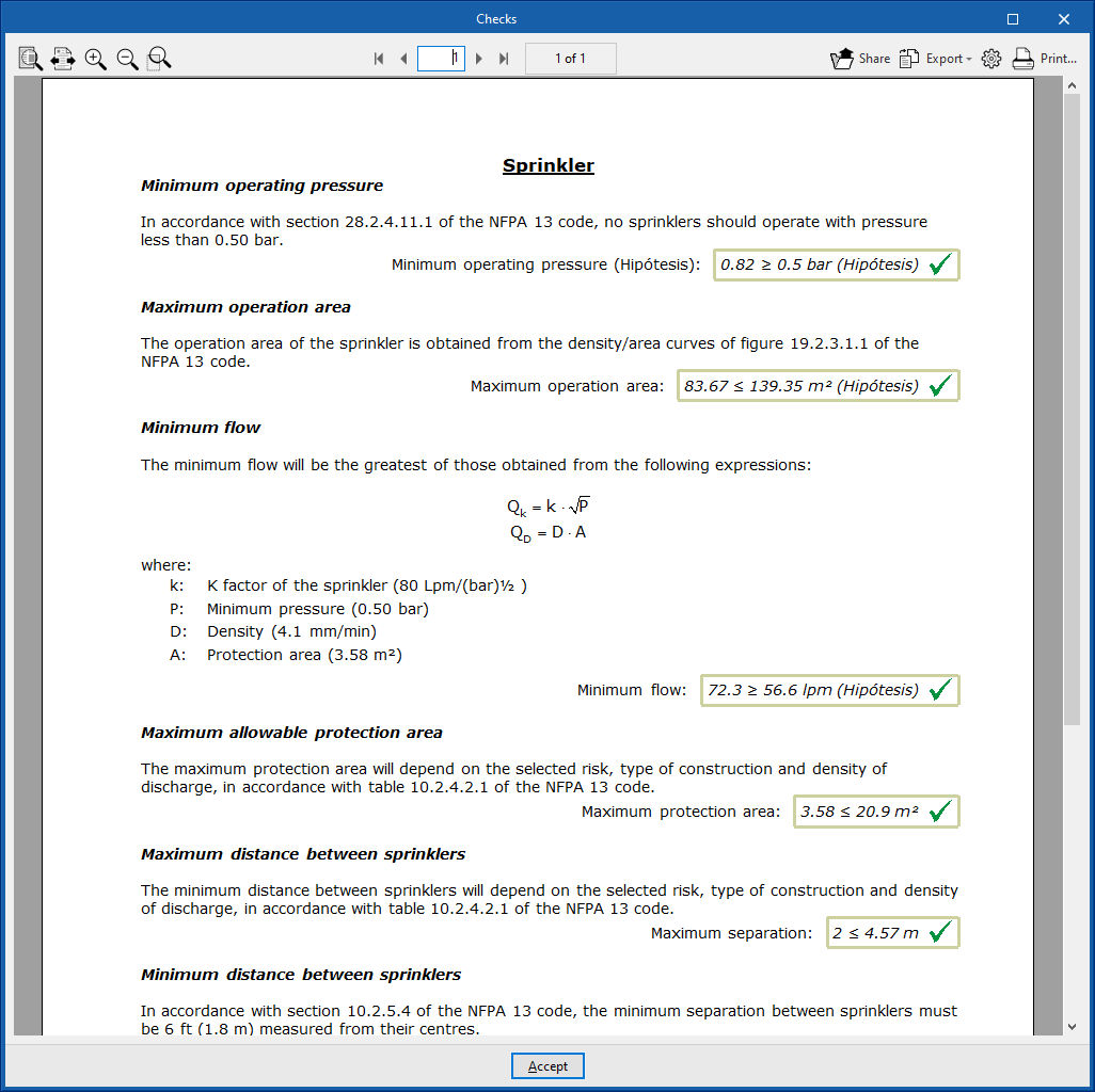
Checks by type of space
This section activates and configures the checks to be carried out for each type of space entered according to its risk.
For each type of space, the program allows the following parameters to be defined:
- Reference
Reference of the type of space, according to its risk. - Description
Description of the type of space. - Design options
For each of the following options and checks, a configurable descriptive text can be entered in addition to the numerical value associated with them:- Design density (Fixed value/ Defined by points) (optional)
Amount of water discharged per unit time by the sprinkler installation over a given area. It can be expressed with a fixed value or by a curve that obtains the design density to be considered from the area of operation of the active sprinklers. - Minimum operating pressure
Minimum pressure to be achieved in sprinklers. - Minimum design flow
Minimum permissible flow rate to be provided by sprinklers. To be taken from the maximum obtained from the three equations shown:- Q = k * (Pmín)1/2 (optional)
Flow rate (Q) expressed as a function of the discharge factor (k), defined in the sprinkler type, and the minimum operating pressure at the sprinkler (Pmin). - Q = D * A (optional)
Flow rate (Q) expressed as a function of design density (D) and area of operation (A). - Fixed value (in units of volume/time) (optional)
This value is directly editable by the user.
- Q = k * (Pmín)1/2 (optional)
- Minimum duration of water supply (optional)
If the system is based on a tank, the tank shall be capable of supplying water for the minimum time set out in this section. - Maximum operation area (By surface area / By sprinklers)
Maximum value of the area of operation, expressed by surface area or by the number of sprinklers that are active. - Maximum protected surface by control valve set (optional)
If the installation has a control post, the area protected by the control post shall not exceed this value. - Restrictions
Sets installation restrictions, defining the type of response for each type of sprinkler. Sprinklers of different response types cannot be installed together, depending on whether or not the boxes at the bottom of the dialogue box are checked.- Type of sprinkler (Standard sprinkler / Standard sprinkler sidewall / Residential sprinkler / ESFR sprinkler / All types / Type of response (Standard / Rapid / All types)
- Allow for sprinklers with a different response to be installed (optional)
- Allow for the installation of "Residential sprinkler" with other types of sprinklers (optional)
- Design density (Fixed value/ Defined by points) (optional)
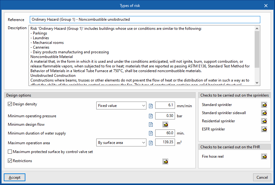
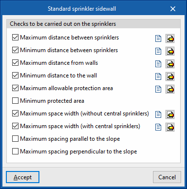
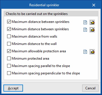
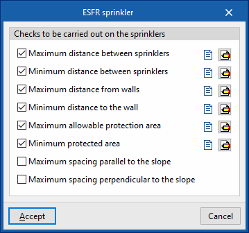
- Checks to be carried out on the sprinklers
The following checks can be activated and configured for the different sprinkler types: "Standard sprinkler", "Standard sprinkler sidewall", "Residential sprinkler", "ESFR sprinkler":- Maximum distance between sprinklers (Fixed value / Depending on the discharge density) (optional)
- Minimum distance between sprinklers (optional)
- Maximum distance from walls (Fixed value / Depending on the discharge density) (optional)
- Minimum distance to the wall (optional)
- Maximum allowable protection area (Fixed value / Depending on the discharge density) (optional)
- Minimum protected area (optional)
- Maximum space width (without central sprinklers) (optional) [only with "Standard sprinkler sidewall"]
- Maximum space width (with central sprinklers) (optional) [only with "Standard sprinkler sidewall"]
- Maximum spacing parallel to the slope (optional)
- Maximum spacing perpendicular to the slope (optional)

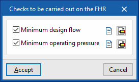
- Checks to be carried out on the FHR
The following checks can be activated and configured to be carried out on fire hose reels:- Minimum design flow
- Minimum operating pressure
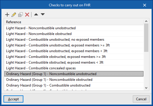
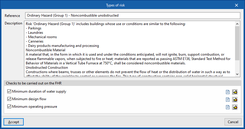
Checks to be carried out on the fire hose reels
In this section, the checks to be carried out on the fire hydrants equipped for each type of risk are activated and configured.
For each type of risk in the report, the program defines the following parameters:
- Reference
Reference of the type of risk. - Description
Description of the type of risk. - Checks to be carried out on the fire hose reels
The following checks can be activated and configured to be carried out on the fire hose reels:- Minimum duration of water supply
- Minimum design flow
- Minimum operating pressure
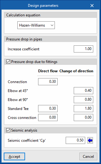
Design parameters
- Calculation equation
Selects the equation for calculating the pressure drop:- Hazen-Williams
The Hazen-Williams calculation method is one of the most widely used due to its simplicity of calculation, but it cannot be used with any liquid other than water. This is the default method selected. - Darcy-Weisbach
The Darcy-Weisbach calculation method is more accurate than the previous one, but more complex, due to the calculation of the friction factor. This method is required in certain specific cases by some standards, such as NFPA 13. The choice of this calculation method allows the following parameters to be set:- Specific gravity
Ratio of fluid density to water density at 4°C. - Relative viscosity
Ratio of the kinematic viscosity of the fluid to that of water at 20°C. - Precision
Convergence criterion used to indicate that the solution to the non-linear equation has not been found. The iterative calculation ends when the sum of all flow differences divided by the sum of all line flows is less than the number indicated in this section.
- Specific gravity
- Hazen-Williams
- Pressure drop in pipes
Inserts a safety coefficient which increases the pipe lengths to simulate pressure losses due to singular elements such as elbows, crosses, tees, valves, etc.- Increase coefficient
This value must be greater than the unit. For example, to represent a head loss increase of 15%, a value of 1.15 is entered.
- Increase coefficient
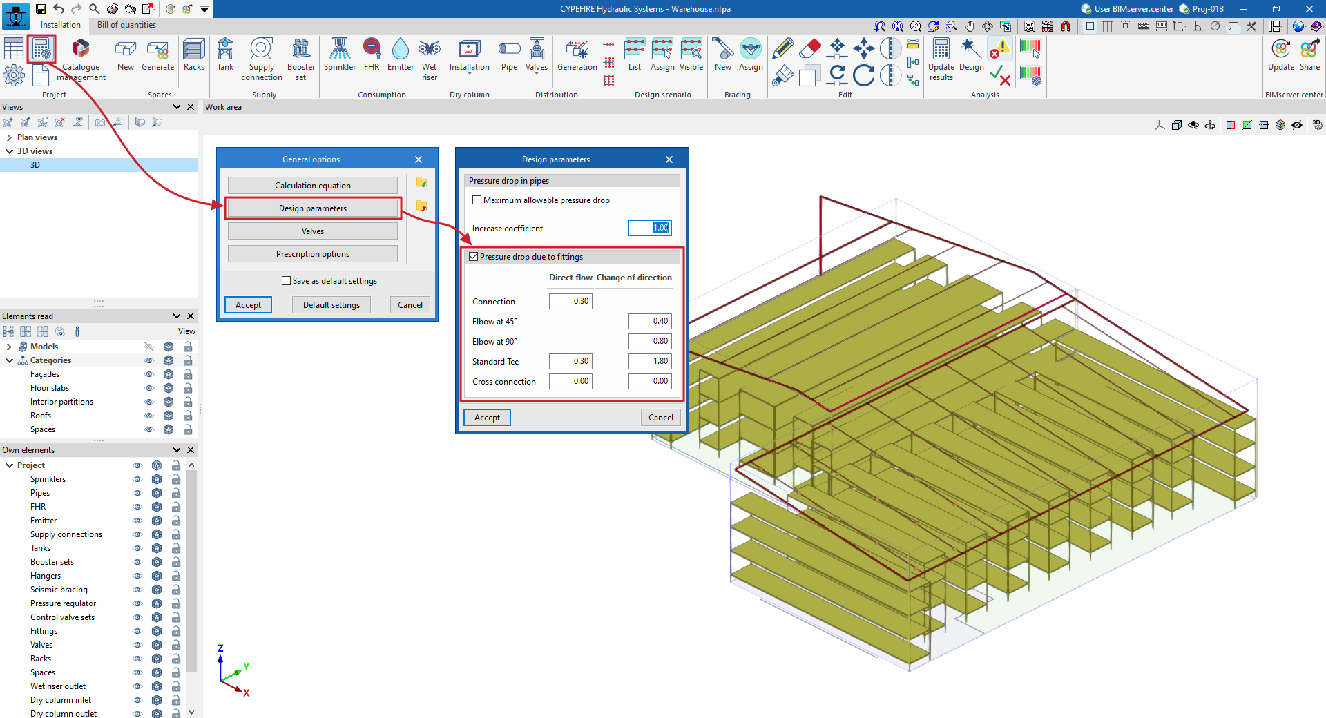
- Pressure drop due to fittings (optional)
By activating this option, fittings such as connections, elbows, tees or crosses are generated during the calculation according to the geometry of the network and can be displayed in the 3D representation of the system. Furthermore, in this section, the program can configure the head loss coefficient associated with the different types of fittings generated, both in the branch with direct flow and in the branch with change of direction, if applicable.- Connection (Direct flow)
- Elbow at 45º (Change of direction)
- Elbow at 90º (Change of direction)
- Standard Tee (Direct flow, Change of direction)
- Cross connection (Direct flow, Change of direction)
- Seismic analysis (optional)
By activating this option and setting the following parameter, users can enter and analyse seismic bracings in the installation using the options in the "Bracings" group of the main toolbar.- Seismic coefficient 'Cp'
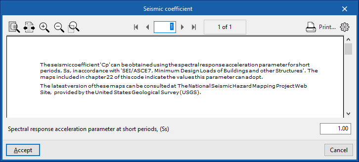
This can be entered directly or using the wizard on the right to obtain it from the "Spectral response acceleration parameter at short periods (Ss)", according to "SEI/ASCE 7, Minimum Design Loads of Buildings and other Structures".
- Seismic coefficient 'Cp'

Pipe options
- Checks
Activates and configures the following checks on the pipes:- Maximum velocity (optional)
Maximum velocity of the fluids permitted in pipes. - Maximum allowable pressure drop (optional)
Maximum allowable pressure drop ratio for any given pipe span, expressed as a percentage. If the pressure difference between the initial and final nodes is greater than the indicated value, a warning shall be displayed on the pipe warning that the span must be redesigned.
This option is used to quickly detect spans that, due to their dimensions, produce large head losses and therefore need to be redesigned. The default value is 40%.
- Maximum velocity (optional)
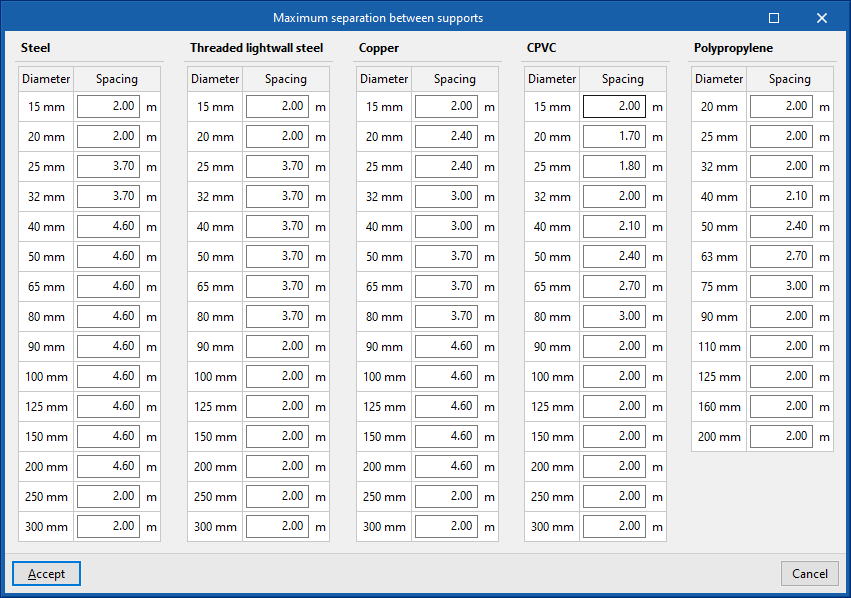
- Quantities
- Generate the support quantities (optional)
Activating this option automatically generates the measurement of the pipe supports from the geometry of the installation entered in the model. The option on the right configures this measurement by editing the "Maximum spacing between supports" for the different pipe materials and diameters.
- Generate the support quantities (optional)

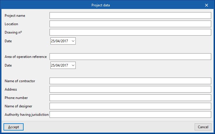
Project data
Incorporates the following project data into the program so that it can be used and displayed in the report composition:
- Project name
- Location
- Drawing reference / Date
- Area of operation reference / Date
- Name of contractor
- Address
- Name of designer
- Authority having jurisdiction
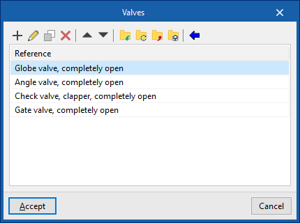
Valves
Defines types of valves. These elements can be entered in the model from the ‘’Valves‘’ option in the ‘’Distribution‘’ group of the main toolbar.
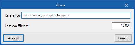
The data associated with each valve is as follows:
- Reference
Valve reference. - Loss coefficient
Pressure loss coefficient associated with the valve.
The wizard to the right of the top of the list can import ‘’Predefined valve types‘’ included in the program.
Sizing rules
Configures the design criteria used by the program by clicking on the "Design" option in the "Calculation" group of the main toolbar:
- Diameter / Sprinklers (optional)
The program will modify the diameter of the pipes according to the number of sprinklers it supplies.
Some diameters are only available for polypropylene pipes.

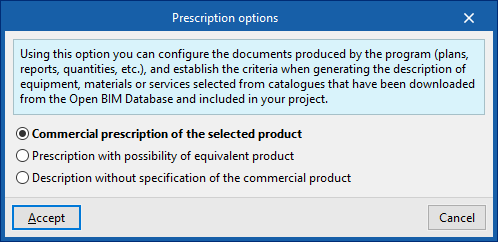
Prescription options
This option is used to configure the documents produced by the program (drawings, reports, quantities, etc.), establishing the criteria for generating the descriptions of the equipment, materials or services selected from the catalogues downloaded from the Open BIM Database and included in the project.
- Commercial prescription of the selected product
The description of the equipment, materials and services will prescribe the selected product exclusively. - Prescription with the possibility of an equivalent product
The description of the equipment, materials and services shall prescribe the selected product indicating the possibility of using an equivalent product. - Description without specification of the commercial product
The description of the equipment, materials and services shall not specify a particular commercial product.
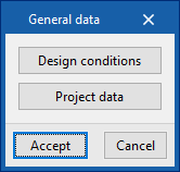
Entering project data
In the "Installation" tab, in the "Project" group of the main toolbar, there is an option to enter the project data:

The following options are available:
- Design conditions
- Project data
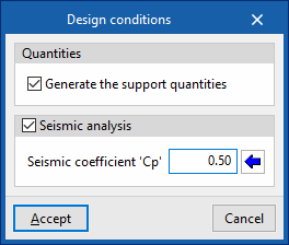
Design conditions
The following data can be defined:
- Quantities
- Generate the support quantities (optional)
Activating this option automatically generates the measurement of pipe supports based on the geometry of the installation entered in the model. These quantities can be configured by editing the "Maximum separation between supports" for different materials and pipe diameters. This option is located in "Regulatory settings" within the "Project" group.
- Generate the support quantities (optional)
- Seismic analysis (optional)
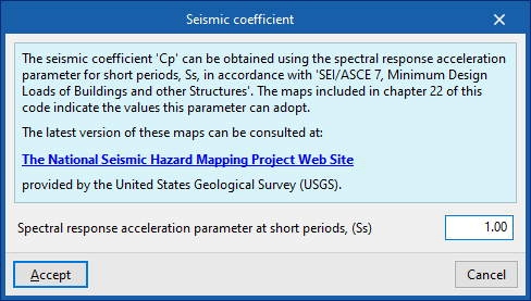
When this option is activated, and the following parameter is configured, it is possible to enter and analyse seismic bracing in the installation using the options in the "Bracing" group on the main toolbar.- Seismic coefficient 'Cp'
It can be entered directly or the assistant on the right can be used to obtain it from the "Spectral acceleration parameter for short periods (Ss)", in accordance with "SEI/ASCE 7, Minimum Design Loads of Buildings and Other Structures".
- Seismic coefficient 'Cp'
| Note: |
|---|
| The maps included in chapter 22 of the SEI/ASCE 7 standard indicate the values that the "Ss" parameter may take. These data can also be consulted in the following web information provided by the United States Geological Survey (USGS): The National Seismic Hazard Mapping Project Web Site. |
Project data
Enters the following project data into the program so that it can be used and displayed in the report composition:
- Project name
- Location
- Drawing nº / Date
- Area of operation reference / Date
- Name of contractor
- Address
- Phone number
- Name of designer
- Supervising entity
Tools for managing manufacturers' catalogues
Within the "Installation" tab, in the "Project" group of the main toolbar, there is an option for managing the manufacturer's product catalogues to incorporate them into the project:

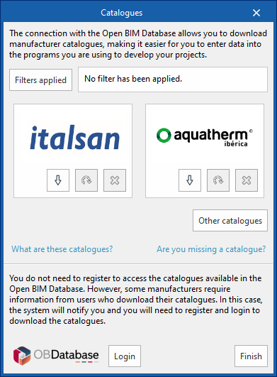
Catalogue management
Manufacturer's catalogues can be downloaded using the Open BIM Database connection, making it easier to enter data into the program for project development.
Clicking on this option opens a window with the available manufacturer catalogues.
Using the "Filters applied" option, it is possible to apply filters by element "Category", "Language" and "Country", in order to display only manufacturers offering product catalogues with these characteristics.
Catalogue download
For each manufacturer, the following options are shown:
- Download
Download the manufacturer's catalogue. The products in the catalogue will be available in the project. - Update
Updates the selected manufacturer's catalogue to the latest version, deleting the version downloaded in the project. - Delete
Deletes the catalogue of the selected manufacturer. The products in the catalogue will no longer be available in the project.
Connection to the Open BIM Database
At the bottom of this dialogue box, the program allows users to log in with their Open BIM Database account and password.
| Note: |
|---|
| The products from the downloaded catalogues can be selected when entering the elements of the system. |
Entering spaces
Within the "Installation" tab, in the "Spaces" group of the main toolbar, there are options for entering and generating spaces in the model:

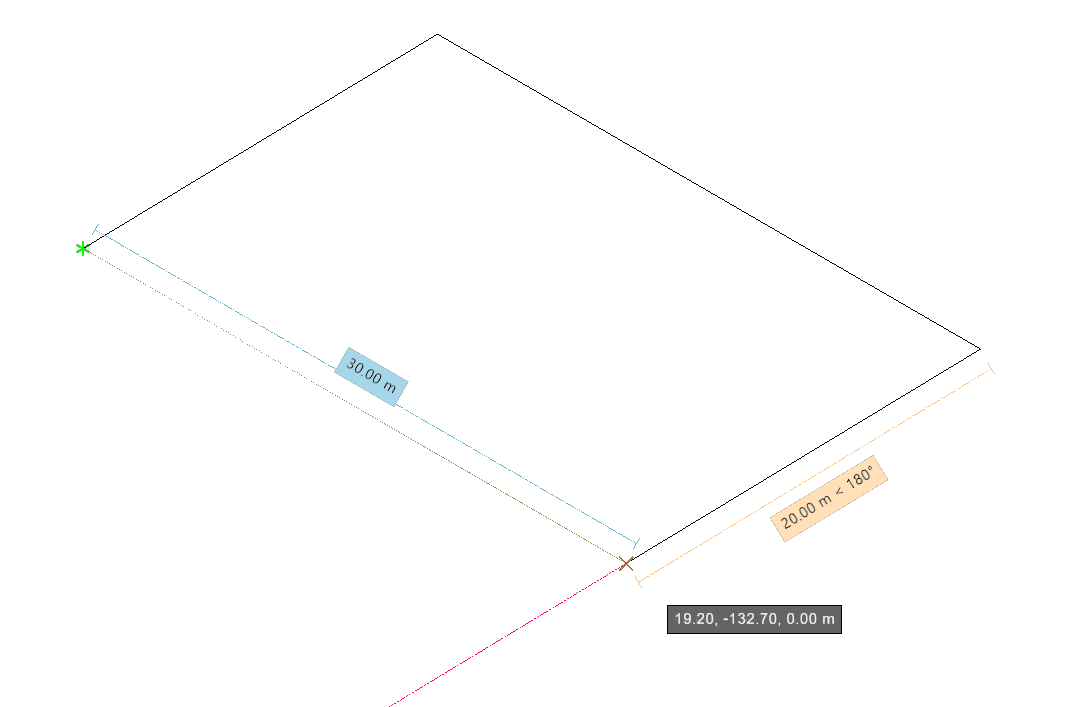
New
Enters a new space by drawing it directly in the program freely.
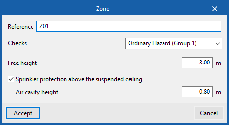
When entering a space, the program allows users to define the following parameters:
- Reference
Space reference. - Checks
Assigns the checks to be carried out in the space. Using the wizard on the right, one of the previously defined checks can be imported. The tools available in "Checks by type of space", accessible from "Code configuration", in the "Project" group, are used to create and configure the checks in the spaces. - Free height
Free height value of the space. - Sprinkler protection above the suspended ceiling (optional)
Checking this box indicates that protection is required for the space above the suspended ceiling. The value for the "Air cavity height" must be entered. In this case, during the automatic sprinkler generation process in the space, two layers of sprinklers will be generated, one above the suspended ceiling, covering the air cavity space, and another below.
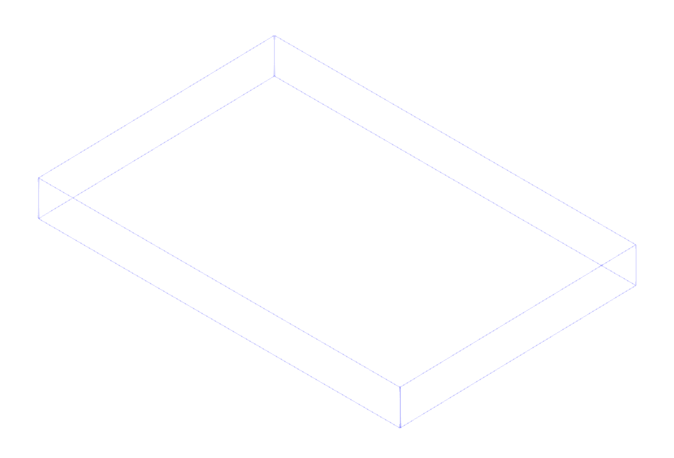
Then, the outline of the space is drawn in plan.
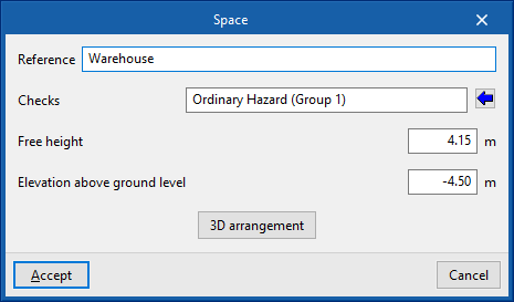
When editing a previously entered space, the "Reference", "Checks" and "Free height" can be modified, as well as the "Elevation above ground level" and the "3D arrangement" of the space. In the latter, the absolute "X" and "Y" coordinates of the vertices of each of the polygons that define its plan outline are defined.

Entering racks
Within the "Installation" tab, in the "Spaces" group of the main toolbar, there is an option for simulating the existence of racks in the project:

Racks
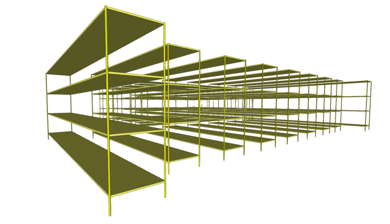
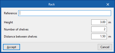
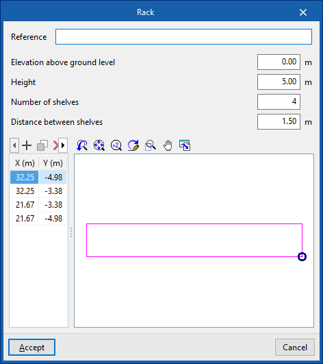
Inserts racks into the model.
The existence of racks can affect the analysis of ESFR sprinklers: the "Maximum sprinkler spacing" or the "Maximum distance from walls" is limited depending on the height of the racks according to some standards such as NFPA 13. These limits can be considered and adjusted in "Checks to be carried out on the sprinklers", which can be found under "Checks by type of space", in the "Code configuration", in the "Project" group.
When entering a rack type element, users can set the following parameters in the program:
- Reference
Rack reference. - Height
Rack height.
Then, the contour of the rack is drawn in plan. The program automatically generates the rack geometry from this information.
When editing a previously entered rack, in addition to its "Height" and "Reference", it is also possible to modify the "Elevation above ground level" and the absolute coordinates "X" and "Y" of the vertices of the polygon that defines its plan outline.
Defining the supply of the fire extinguishing installation
Within the "Installation" tab, in the "Supply" group of the main toolbar, the elements that make up the supply of the hydraulic fire extinguishing system can be defined and entered:

Tank
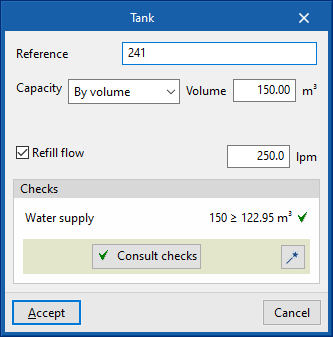
Enters a tank to act as the initial supply point for the installation.
When entering or editing a tank, the following parameters can be configured:
- Reference
Tank reference. - Capacity
Defines the capacity of the tank by entering the volume value directly or by indicating its dimensions.- By volume (Volume)
- By dimensions (Radius, Height)
- Refill flow (optional)
The refill flow rate reduces the volume required to supply the installation. In this way, a tank with reduced capacity can be simulated.
After the analysis, the program also displays the checks carried out on the tank in its editing panel, as well as the possibility of designing the tank with the tool available in the lower right-hand corner to comply with these checks.
The minimum water supply time can be defined for each type of space under "General options" in the "Project" group of the top toolbar.
| Note: |
|---|
| To increase the network pressure, a "Pressure group" can be entered downstream of the tank using the corresponding option in the "Supply" group. |

Supply connection
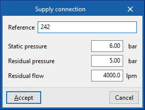
Enters a connection into the public network to act as the initial supply point for the installation.
When entering or editing a public network connection, the following parameters can be configured, which can be evaluated by specific tests and which describe the capacity of the network:
- Reference
Supply connection reference. - Static pressure
Value of the supply pressure measured with the fluid at rest. - Residual pressure
Value of the pressure in the supply connection measured at the residual flow rate of flowing water. - Residual flow
Water flow sustained by the public network while maintaining the indicated residual pressure.

Booster set
Enters a booster set into the installation
When entering or editing a pressure group, the following parameters can be configured:
- Reference
Booster set reference. - Catalogue / Selection
The program can be used to select a pressure group from the manufacturer's catalogues included in the Open BIM Database. These can be downloaded from the "Catalogue management" option in the "Project" group.

Entering consumptions: sprinklers, fire hose reels and emitters
In the "Installation" tab, in the "Consumption" group of the main toolbar, the consumption of the hydraulic fire extinguishing system can be defined and entered: sprinklers, fire hose reels, emitters and wet standpipe outlets:

Sprinklers
Enters sprinklers into the model one at a time along with their associated protection area.
| Nota: |
|---|
| To enter sprinkler groups or to generate them automatically from the geometry of the spaces, together with the distribution pipes, the corresponding options can be used in the "Distribution" group in the upper toolbar. |
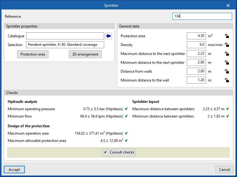
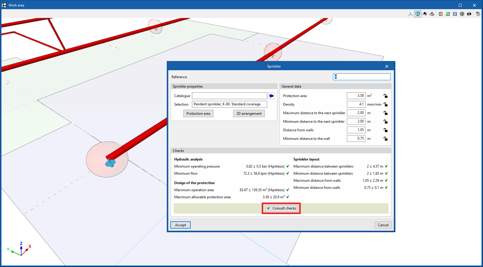
When entering a sprinkler, the following parameters can be configured:
- Reference
Sprinkler reference. - Catalogue / Selection
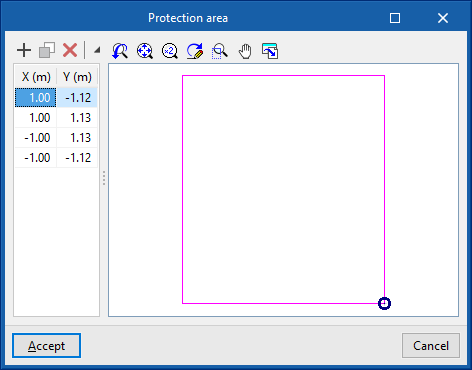
The program can be used to select a sprinkler from the manufacturer's catalogues included in the Open BIM Database. These can be downloaded from the "Catalogue management" option in the "Project" group. - Protection area
Enters the parameters defining the area protected by the sprinkler, which can be rectangular or circular. The program reports the "Surface" of the protected area obtained based on these parameters.- Rectangular (Dimensions)
- Circular (Radius)
When editing a previously entered sprinkler, the geometry of the generated "Protection area" can be modified by entering the "X" and "Y" coordinates defining the points of its perimeter relative to the sprinkler.
The "3D layout" of the sprinkler can also be modified by editing the following parameters:
- X, Y, Z
Absolute coordinates of the sprinkler position in the model. - Ux, Uy, Uz / Vx, Vy, Vz
Components of the U and V vectors that determine the sprinkler orientation plane.
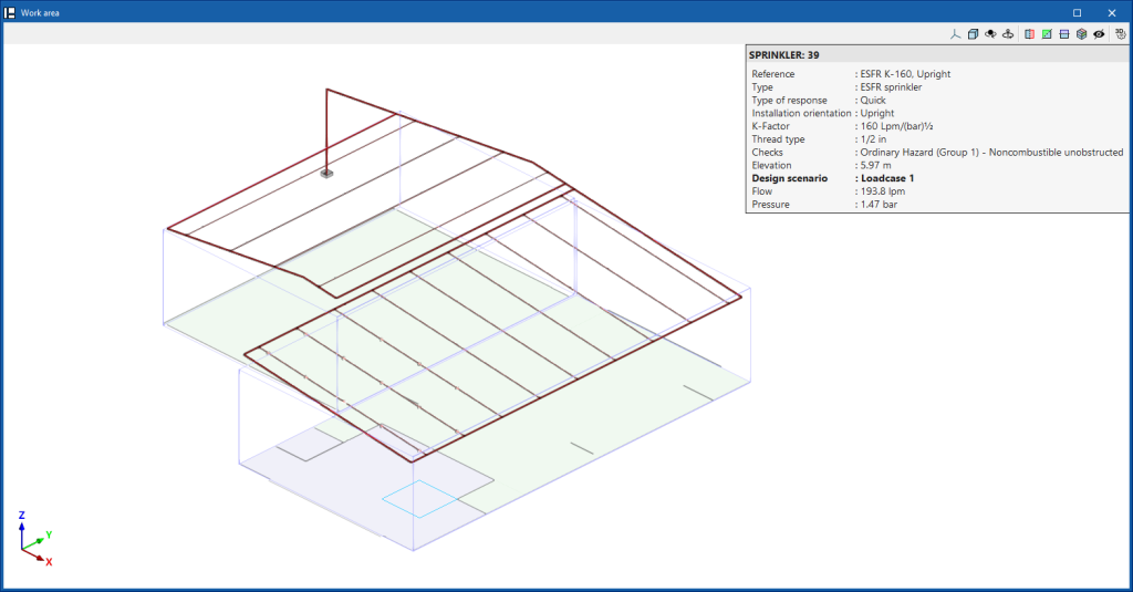
During the analysis, the program displays the following general data. This data can be locked or unlocked. If they are locked, the users can impose their value. By keeping them unlocked, the program can modify them by taking information from the model and the analysis results:
- Protection area
- Density
- Maximum distance to the next sprinkler
- Minimum distance to the next spinkler
- Distance from walls
- Minimum distance to the wall
The checks to be carried out on the sprinklers can be defined for each type of space in "General options", in the "Project" group in the top toolbar. After the analysis, the program allows the verification of each of the checks defined in the sprinkler editing panel to be consulted.

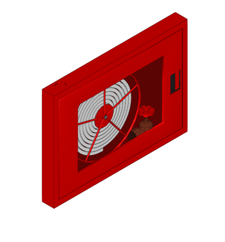
Fire hose reels
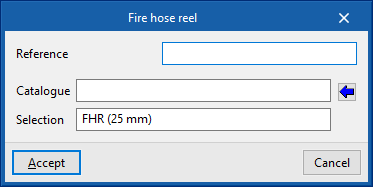
Inserts a fire hose reel.
When entering or editing a fire hose reel, the following parameters can be configured:
- Reference
Fire hose reel reference. - Catalogue / Selection
The program can be used to select a fire hose reel from the "Manufacturer's catalogues" if available, or from the "Generic elements library" using the wizard available on the right. These types of elements can be created and edited from the "Catalogue management" and "Generic elements library" options, respectively, within the "Project" group. - Checks
Selects the checks to be carried out on the fire hose reel. The Checks to be carried out on the fire hose reels" can be defined in "General options" in the "Project" group of the top toolbar. This section appears after selecting a fire hose reel from the catalogue.
The checks to be carried out on fire hose reels can be defined for each type of space in "General options" in the "Project" group of the top toolbar.

Emitters
Inserts a generic emitter.
The emitters allow the simulation, analysis and hydraulic design of any element of a fire extinguishing installation (sprinklers, fire hose reels, hydrants, etc.), without depending on the geometric and hydraulic restrictions of the sprinklers and fire hose reels that are entered through the other options in this group.
When entering or editing an emitter, the following parameters can be configured:
- Reference
Emitter reference. Identifies the element entered in the report. - K-Factor
Discharge factor of the emitter for calculating the flow rate.
The program does not perform any checks on the emitters but, thanks to the EPANET calculation engine, it is able to perform the hydraulic analysis of the designed system. Furthermore, on the program interface, the flow and pressure data obtained for each of the emitters entered can be displayed.


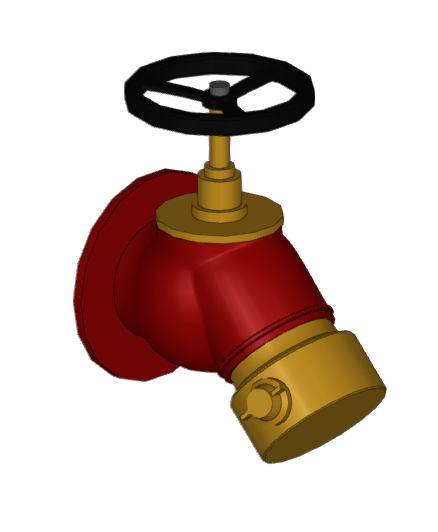
Wet riser
Enters a wet riser outlet.
This element acts in the same way as a sprinkler, fire hose reel or emitter, being connected at any point in the system and assigned to the desired design scenarios in order to obtain the flow rate and pressure resulting from the analysis.
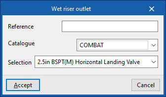
When entering or editing an outlet for a wet riser, the following parameters can be configured:
- Reference
Reference for the wet riser outlet. - Catalogue / Selection
The program can be used to select a wet riser outlet from the manufacturer's catalogues included in the Open BIM Database. These can be downloaded from the "Catalogue management" option in the "Project" group.
As with the emitters, the program does not carry out any regulatory checks on the wet riser outlets, but, thanks to the EPANET analysis engine, it is able to carry out the hydraulic analysis of the designed system. Moreover, on the program's interface, it is possible to visualise the flow and pressure data obtained for each of the wet riser outlets entered.
Inserting pipes and elements of the water distribution network
Within the "Installation" tab, in the "Distribution" group of the main toolbar, pipes and elements in the water distribution network such as valves, pressure and flow regulators and control points can be defined and entered manually.

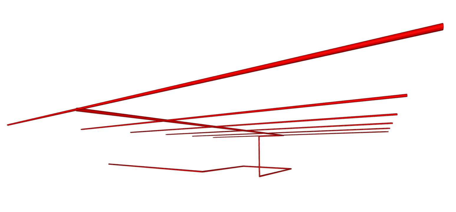
Pipes
Freely inserts pipes into the model in any direction in space, tracing their layout in the work area.
| Note: |
|---|
| To enter pipe networks as a whole or to generate them automatically from the geometry of the spaces, together with the sprinklers they feed, the corresponding options on the right-hand side of the "Distribution" group can be used. |
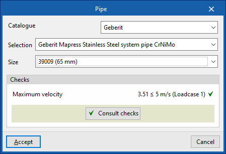
When entering a pipe, the following parameters can be configured:
- Catalogue / Series / Diameter
The program selects pipes from "Manufacturer catalogues", if available, or from the "Library of generic elements" using the wizard available on the right. These types of elements can be created and edited from the "Catalogue management" and "Library of generic elements" options, respectively, within the "Project" group.
The checks to be carried out on the pipes can be defined in "Pipe options", accessible from "General options", in the "Project" group of the top toolbar. After the analysis, the program can consult the verification of the checks defined in the editing panel of each pipe span.
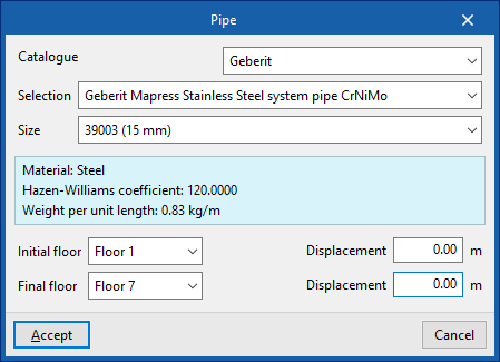
Riser
Enters a vertical pipe or riser by specifying a "Initial floor" and an "Final floor". On each of these floors it is possible to specify a "Displacement" to adjust the position of the end points of the riser.
The remaining parameters are identical to those that appear when using the "Pipe" option.
The "Valves" menu allows you to enter elements of the "Valve", "Control station", "Pressure regulator", and "Flow regulator" types:
Valves
Inserts a valve into the distribution network. This way, the program considers the associated pressure losses.
When entering or editing a valve, the following parameters can be configured:
- Reference
Valve reference. - Selection
The program selects a valve from the "Library of generic elements" using the wizard available on the right. These types of elements can be created and edited from the "Library of generic elements" option in the "Project" group.
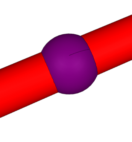

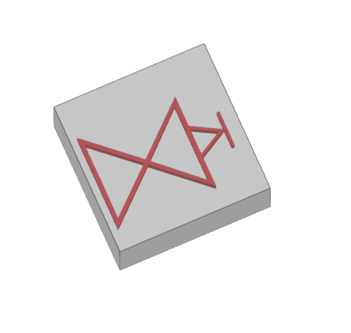
Control valve set
Inserts a control valve set.
The control valve set is an assembly comprising the alarm valve, the shut-off valve, and all valves and fittings needed to control a hydraulic extinguishing installation.
The maximum size of the installation controlled by a control valve set depends on the risk of the building and is set out in the related codes.
The "Maximum protected surface by control valve set" can be defined for each type of space by activating the corresponding option under "General options" in the "Project" group of the upper toolbar.
If the maximum allowable limit is exceeded, the program will report this after the analysis so that the necessary measures can be taken.
| Note: |
|---|
| For the UNE EN 12845 standard, the maximum size of the installation controlled by a control valve set varies between 9000 and 12000 m², depending on the type of risk of the space. |
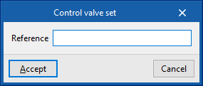
When entering or editing a checkpoint, the following parameters can be configured:
- Reference
Control valve set reference.
Additionally, the design process can be carried out only for the part of the system downstream of a given control point.
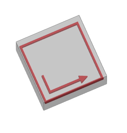
Pressure regulating valve
Inserts a pressure regulating valve.
This element limits the pressure in the hydraulic fire extinguishing system downstream of its installation point.
When entering or editing a pressure regulating valve, the following parameters can be configured:
- Reference
Pressure regulating valve reference. - Limiting pressure
Value of the pressure limited by the regulating valve.
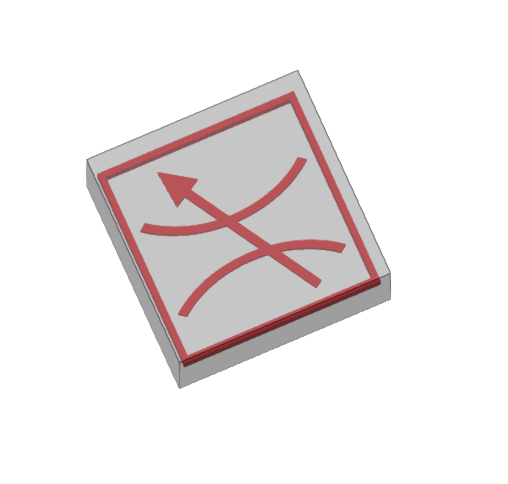
Flow control valve
Inserts a flow control valve.
This element limits the flow in the hydraulic fire extinguishing system downstream of its installation point.
When entering or editing a flow control valve, the following parameters can be configured:
- Reference
Flow control valve. - Limit flow
Flow rate value limited by the control valve.
Automatically generating the water distribution network and inserting branches, manifolds and meshed networks
Within the "Installation" tab, in the "Distribution" group of the main toolbar, there is an option to automatically generate water distribution networks, including pipes and sprinklers, from the geometry of the spaces in the model, as well as options to enter branches, manifolds with branches and complete meshed networks with assistance.

| Note: |
|---|
| To enter sprinklers or pipes individually, the corresponding options can be used in the left-hand side of the "Distribution" group and in the "Consumption" group. |
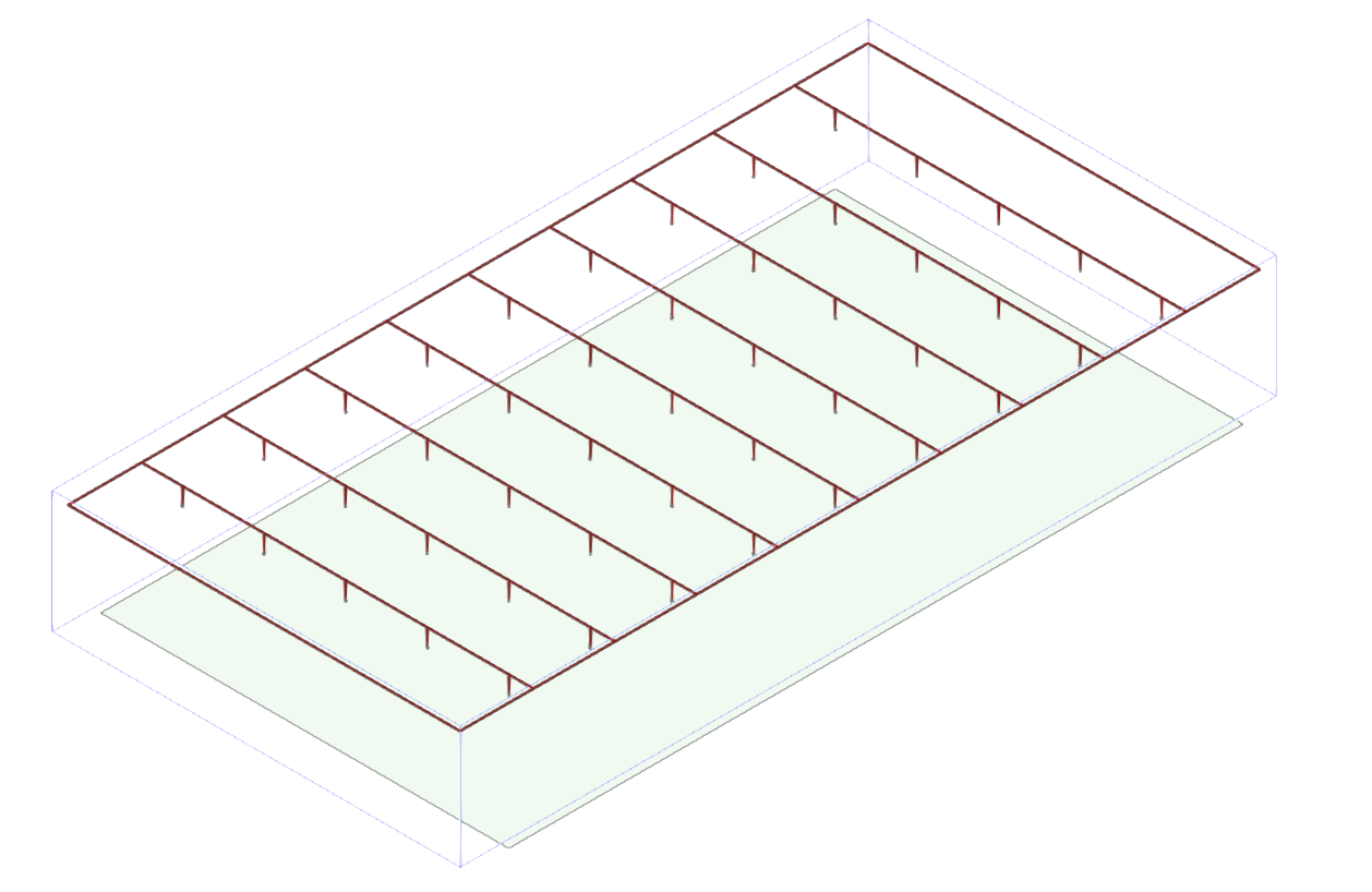
Generation options "By zone" and "Complete"
The "By zone" option allows you to automatically generate a complete water distribution network, including the layout of the pipes and sprinklers, based on the geometry of the selected zones in the workspace.
On the other hand, the "Complete" option automatically generates a sprinkler network in all the building’s zones.
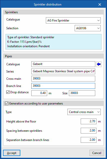
To define the distribution network, in the window that appears when selecting these options, the program allows you to select the sprinklers and the pipes that make it up (including the collectors, the branches and the drop sections leading to the sprinklers) from the manufacturer catalogues included in the Open BIM Database. These can be downloaded from the "Catalogue management" option within the "Project" group.
- Sprinklers
- Catalogue / Selection
The program displays an informational text with the characteristics of the selected product.
- Catalogue / Selection
- Pipes
- Catalogue / Series / Cross main / Branch line / Drop distance (optional)
The "Generation according to user parameters" section can remain deactivated if you want the program to calculate the optimal distances in accordance with the regulations. If activated, it is possible to configure the following parameters:
- Type
- Grid system
The program generates a manifold on the perimeter of the space and draws parallel branches joining points of the space, thus obtaining a grid network. - Central cross main
The program generates a manifold in the centre of the space, from which sprinkler branches are traced, resulting in a branched network.
- Grid system
- Height above the floor
Height of the distribution network above the floor of the space. - Spacing between sprinklers
Separation value between sprinklers in the same branch. - Separation between branch lines
Separation value between branches along the manifold.
The program will generate two layers of sprinklers in zones where the "Sprinkler protection above the suspended ceiling" option is activated. In addition, the generation of the sprinkler network respects openings and columns, and adjusts as far as possible to the outline provided by the model.

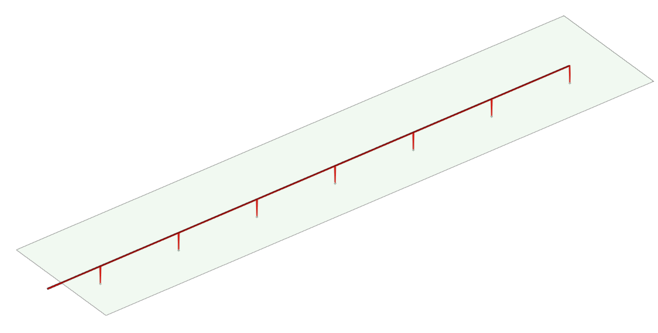
Branch line
Allows the generation of a network branch line, including the definition of the pipes and sprinklers along the branch.
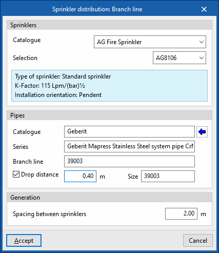
When entering a branch, in the window that appears when this option is selected, the program allows users to select the sprinklers and the pipes included in it (both the branches and the spans up to the sprinklers):
- Sprinklers
- Catalogue / Selection
- Pipes
- Catalogue / Series / Branch line / Drop distance (opcional)
The following parameters can be configured for the branch generation options:
- Spacing between sprinklers
Separation value between sprinklers in the branch.
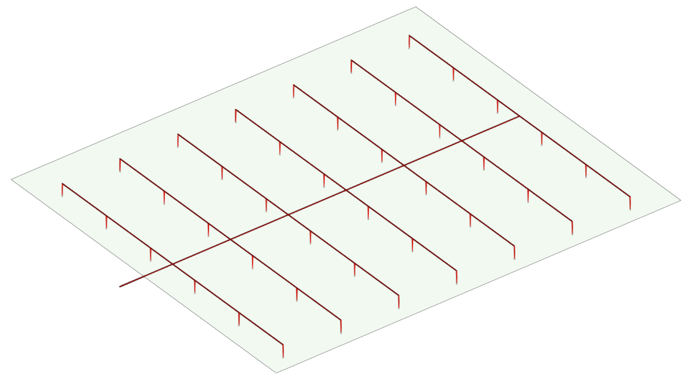
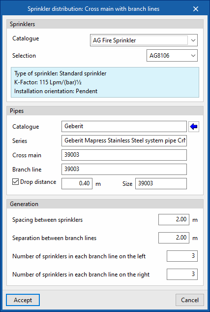
Cross main with branch lines
Generates a network consisting of a manifold with branches to the left and right of it, including the definition of the pipes and sprinklers along them.
When entering a manifold with branches, in the window that appears when this option is selected, the program allows users to select the sprinklers and the pipes included in them (both the manifold and the branches or the spans up to the sprinklers):
- Sprinklers
- Catalogue / Selection
- Pipes
- Catalogue / Series / Cross main /Branch line / Drop distance (optional)
The following parameters can be configured for the generation options of the manifold with branches:
- Spacing between sprinklers
Separation value between sprinklers in the same branch. - Separation between branch lines
Separation value between branches along the manifold. - Number of sprinklers in each branch line on the left / Number of sprinklers in each branch line on the right
Sets the length of each branch to the left and right of the manifold by defining the number of sprinklers to be installed in the manifold.
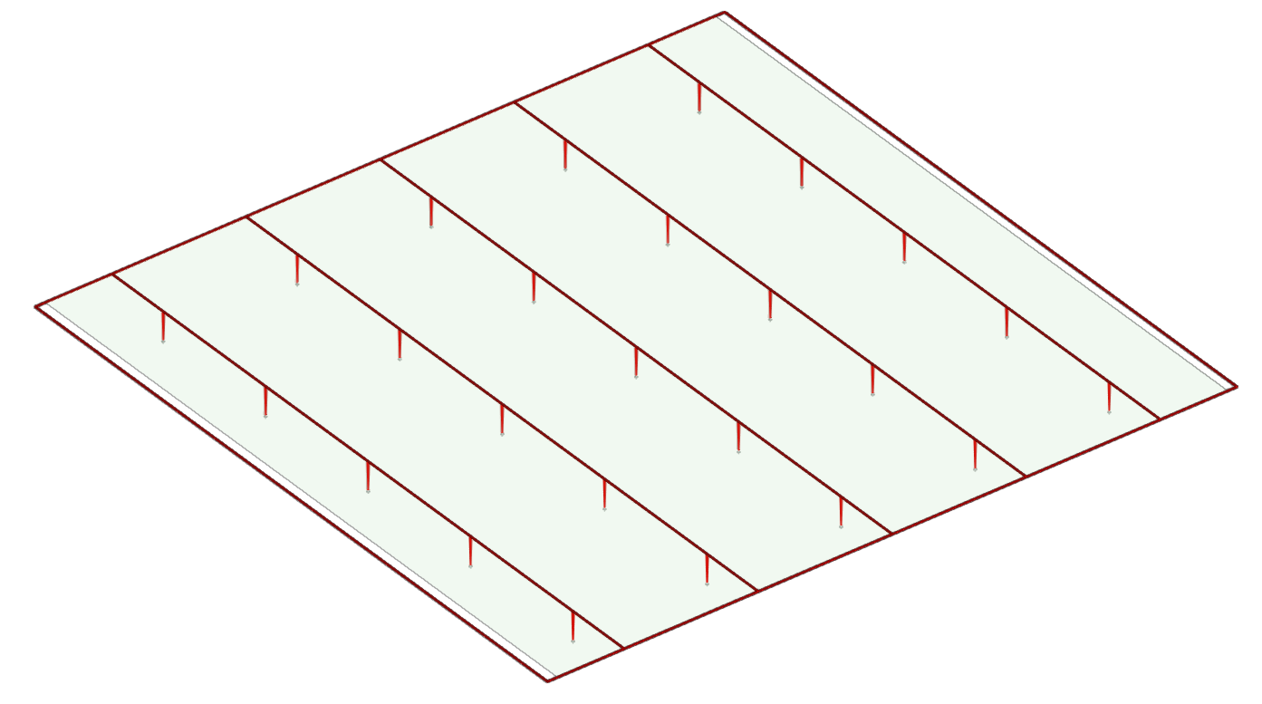
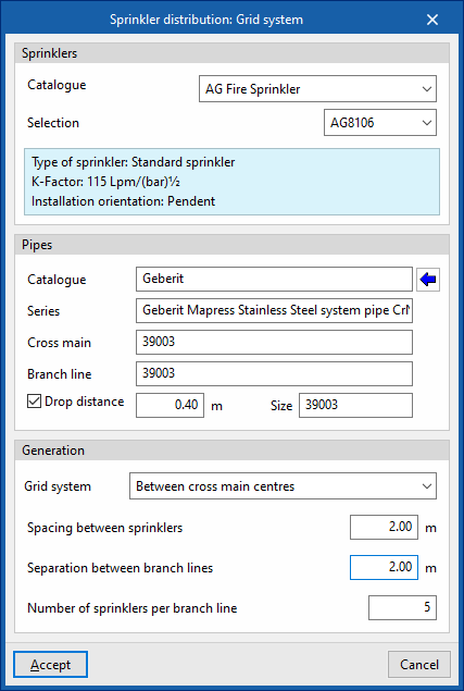
Grid system
Generates a grid system consisting of a perimeter manifold together with parallel branches joining points along the perimeter, including the definition of the pipes and sprinklers along them.
When entering a grid system, in the window that appears when this option is selected, the program allows users to select the sprinklers and the pipes included in them (both the manifolds and the branches or the spans up to the sprinklers):
- Sprinklers
- Catalogue / Selection
- Pipes
- Catalogue / Series / Cross main /Branch line / Drop distance (optional)
The following parameters can be configured for the grid system generation options:
- Grid system (Between cross main centres / With branch lines to the left of the cross main / With branch lines to the right of the cross main.
Defines the position of the manifold and the branches with respect to the network insertion points in the work area. - Spacing between sprinklers
Separation value between sprinklers in the same branch. - Separation between branch lines
Separation value between branches along the manifolds. - Number of sprinklers per branch line
The length of the branches and therefore the spacing between opposing manifolds of the grid system can be established, defining the number of sprinklers to be installed in the branches.
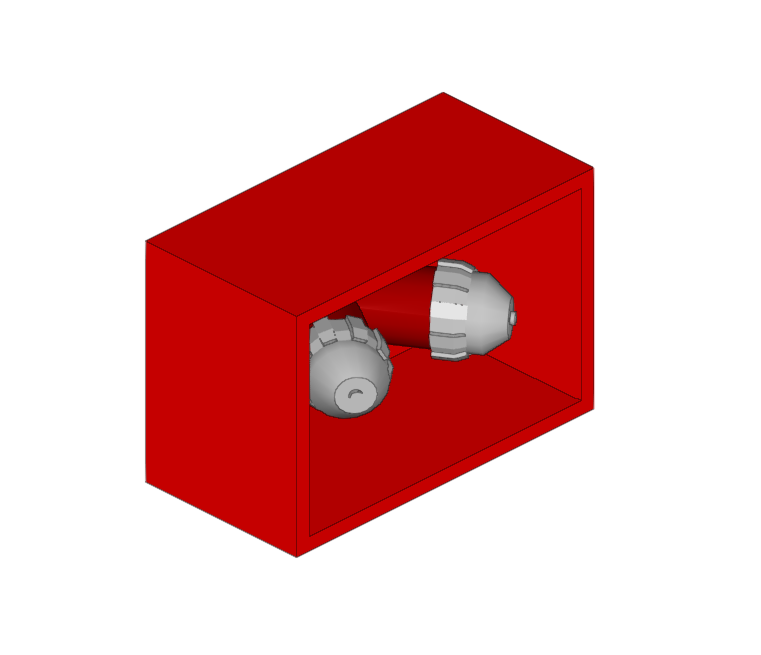
Entering dry columns
Within the "Installation" tab, in the "Dry column" group of the main toolbar, there are options for entering the components of a dry column system in the model:

A dry column system consists of a pipe that is normally empty but, in the event of a fire, can be connected to a pressurised water source on the ground floor, allowing water to be distributed to upper or lower floors of the building, thus facilitating firefighting tasks from inside the building by firefighters. This system is particularly useful in high-rise buildings, where certain floors are inaccessible from the outside.
The "Installation" menu in this group has three options, which adds these elements to the "Work area":
- Dry column inlet
- Pipes
- Dry column outlet
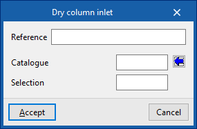
Dry column inlet
Enters a dry column inlet.
When entering or editing the inlet of a dry column, the following parameters can be configured:
- Reference
Dry column inlet reference. - Catalogue / Selection
The program can select a dry column inlet from the manufacturer catalogues included in the Open BIM Database. These can be downloaded from the "Catalogue management" option within the "Project" group.
| Note: |
|---|
| This outlet must be located in a place accessible to the fire services, such as the ground floor façade. |
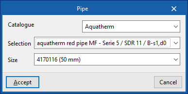
Pipes
Inserts the pipe of a dry column into the model between the inlet and the outlets.
When inserting a pipe, the following parameters can be configured:
- Catalogue / Series / Diameter
The program is used to select pipes from the manufacturer catalogues included in the Open BIM Database. These can be downloaded from the "Catalogue management" option in the "Project" group.

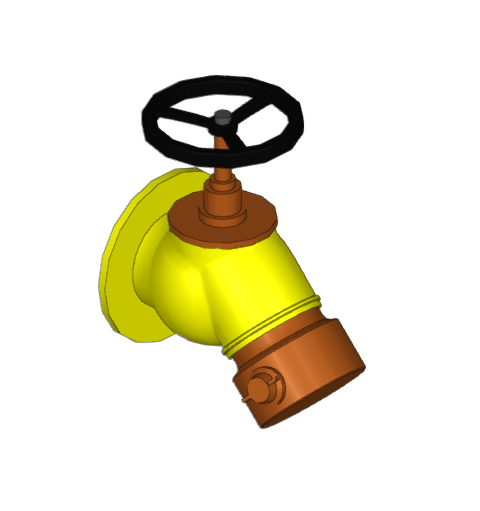
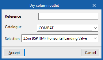
Dry column outlet
Enters dry column outlets on the desired floors.
When entering or editing a dry column outlet, the following parameters can be configured:
- Reference
Dry column inlet reference. - Catalogue / Selection
The program can select a dry column inlet from the manufacturer catalogues included in the Open BIM Database. These can be downloaded from the "Catalogue management" option within the "Project" group.
| Note: |
|---|
| The number and layout of the elements of a dry column system, such as wet columns, may vary according to recommendations or regulatory requirements. |
Generating and editing fittings
Generating fittings and associated pressure drops
Installation fittings such as connections, elbows, tees or cross-connections are automatically generated in the design if the "Pressure drop due to fittings" option is activated in the "Design parameters" under the "General options" available in the "Project" group of the main toolbar of the "Installation" tab.
This option can also be used to configure the pressure drop coefficient associated with the different types of fittings generated, both in the branch with direct flow and in the branch with change of direction, if applicable.
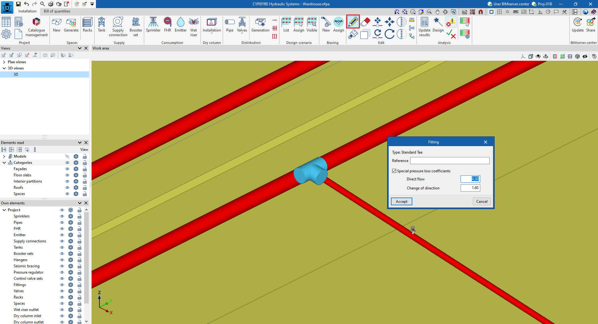
Editing pressure drops in fittings
After the automatic generation, each fitting can be edited manually by using the "Edit" option in the "Edit" group of the main toolbar of the "Installation" tab and clicking on the fitting.
Depending on its type, the pressure drop can be modified both in the branch with direct flow and in the branch with change of direction. To do this, the corresponding option must be activated:
- Type
Type of fitting generated. - Reference
Fitting reference. - Special pressure loss coefficients (optional)
Used to modify the pressure drop coefficients of the fitting.- Direct flow
Pressure drop coefficient in the branch with direct flow. - Change of direction
Pressure drop coefficient in the branch with change of direction.
- Direct flow
The fittings with a modified pressure drop will have a bluer shade so that they can be quickly identified on the installation.
Defining the design scenarios for the fire extinguishing system
In the "Installation" tab, in the "Design scenario" group of the main toolbar, there are tools for defining, assigning and displaying the design scenarios of the fire extinguishing system:

Thanks to these options, the program can define and analyse several different operating scenarios of the elements of the system within the same file.
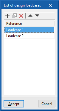
List
Defines the list of scenarios to be considered in the analysis. When adding design scenarios, only their "Reference" needs to be typed in.
| Note: |
|---|
| The program will analyse all the defined design scenarios consecutively when using the "Update results" option in the "Analysis" group. If the "Design" option is used, the design scenarios for which the system is to be designed must be selected. |
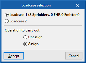
Assign
Used to assign or unassign elements in the fire extinguishing system (sprinklers, fire hose reels and emitters) to any of the defined design scenarios, to indicate that they are open, active or in operation.
If an element is not assigned to a scenario, the program will consider that it is not in operation and will not perform a hydraulic check on it.
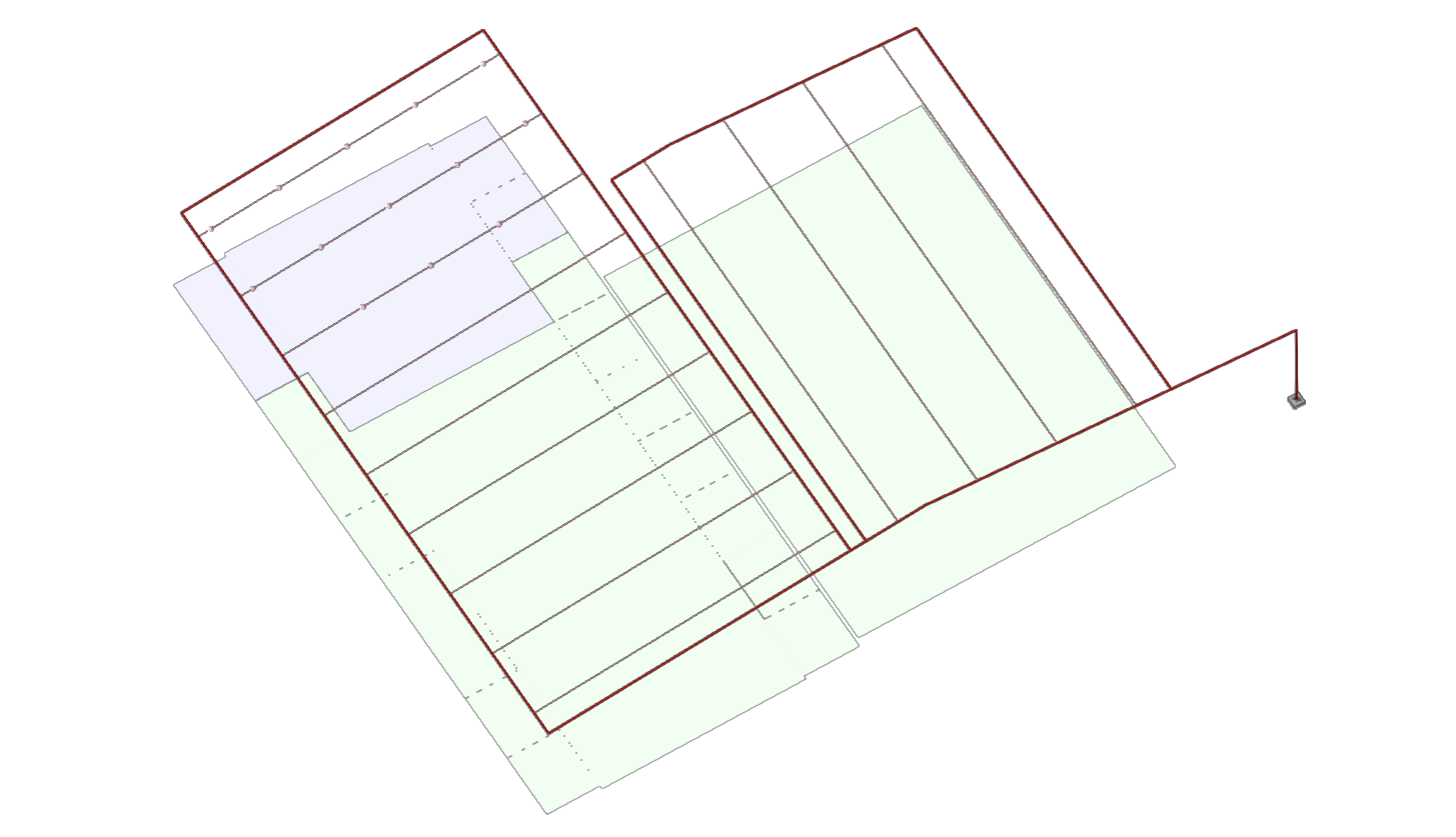
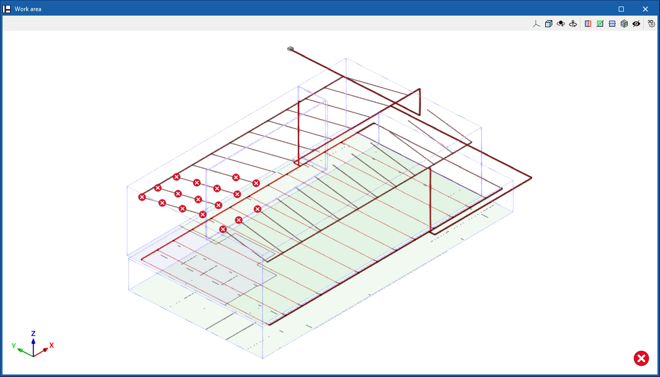
Visible
Used to display a design scenario for the work area.
The program marks the position of the elements that are assigned to the viewed scenario with spheres.
To distinguish it, the operating area of the sprinklers active in the selected scenario, formed by the sum of the areas protected by each sprinkler, is also marked with a colour.
Entering and analysing seismic bracing of the fire extinguishing system
Within the "Installation" tab, in the "Bracing" group of the main toolbar, there are tools for entering seismic bracing and for assigning them a zone of influence consisting of a given set of pipes of the fire extinguishing system:

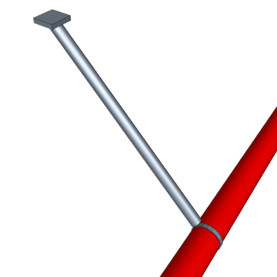
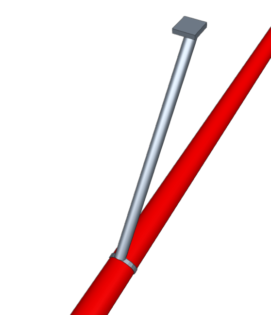
Seismic bracing
Enters seismic bracing into the model.
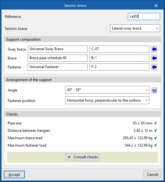
When entering or editing a seismic bracing, the following parameters can be configured:
- Reference
Seismic brace reference. - Seismic brace
Defines the type of seismic bracing from the following options:- Lateral sway brace
The bracing is arranged to be perpendicular to the pipe it supports. - The bracing is arranged in the same direction as the pipe it supports.
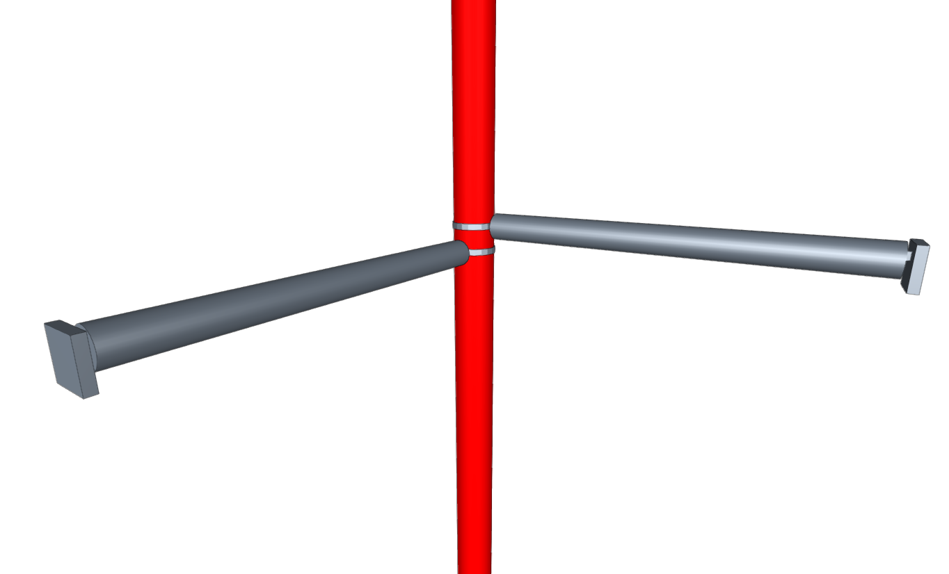
- Four-way sway brace
Two-directional bracing to support vertical pipes.
- Lateral sway brace
- Support composition
Defines the components of the seismic bracing. The program selects components from the manufacturer's catalogues included in the Open BIM Database. These can be downloaded from the "Catalogue management" option in the "Project" group.- Sway brace (Series / Type)
- Brace (Series / Type)
- Fastener (Series / Type)
- Arrangement of the support
- Angle
Angle of the support measured with respect to the vertical line. - Fastener position
- Horizontal force, perpendicular to the surface
- Vertical force, perpendicular to the surface
- Force parallel to the surface
- Angle
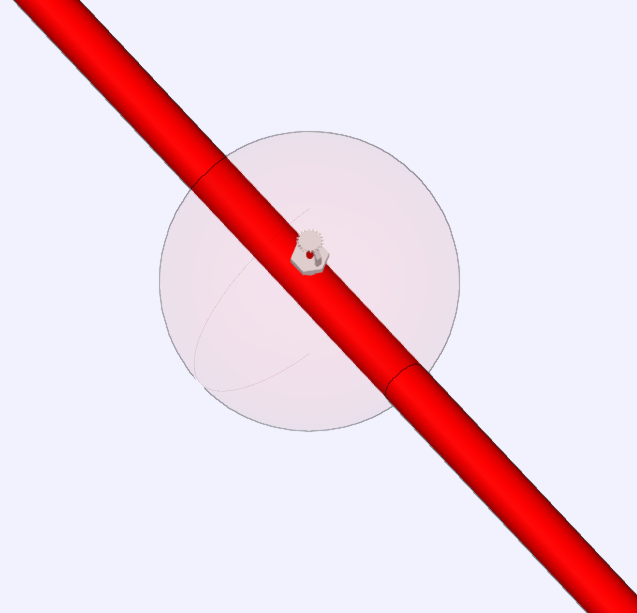
The seismic bracing must then be arranged in the model on a given point of a pipe of the fire extinguishing system.
It is then necessary to assign the pipes in the zone of influence of the bracing using the corresponding option in the same group.
With the data supplied, when carrying out the analysis, the program performs the following checks on the seismic bracing, which can be consulted and listed in the corresponding section of its editing panel:
- Pipe size
Checks that the pipe size of the sway brace is equal to or greater than the diameter of the pipe it holds. - Distance between hangers
Checks that the distance between hangers does not exceed the maximum value. - Maximum brace load
Checks that the load assigned to the brace does not exceed the maximum value allowed by the selected component types. - Maximum fastener load
Checks that the load assigned to the fastening does not exceed the maximum value allowed by the selected component types.
| Note: |
|---|
| To enter seismic bracing, the "Seismic analysis" box must be activated under "General data > Design conditions" in the "Project" group and a seismic "Cp" coefficient must be specified. |
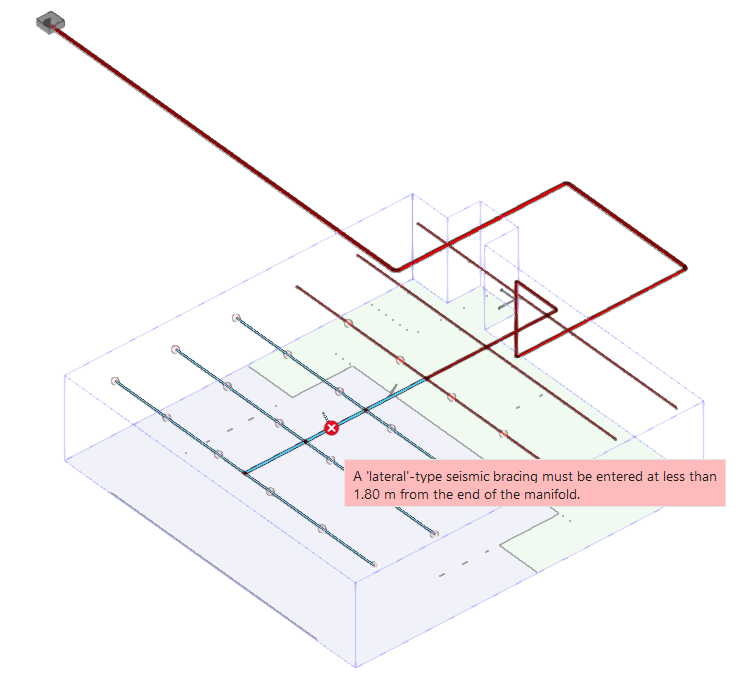
The program also incorporates the following checks during the analysis to ensure the correct distribution of seismic bracing in the installation:
- Detection of the start and end points of manifolds and uprights for the insertion of the corresponding bracings near them.
- Analysis of the distribution of the bracings along the pipes.
- Detection of the sections of the installation without seismic bracing and, therefore, not protected against earthquakes.
These verifications are shown as incidences on the installation in case they are not fulfilled. In order to solve them, the number or layout of seismic bracings in the installation must be modified.
The program also incorporates the following checks during the analysis to ensure the correct distribution of seismic bracing in the system:
- Pipe size
Checks that the pipe size of the sway brace is equal to or greater than the diameter of the pipe it holds. - Distance between hangers
Checks that the distance between hangers does not exceed the maximum value. - Maximum brace load
Checks that the load assigned to the brace does not exceed the maximum value allowed by the selected component types. - Maximum fastener load
Checks that the load assigned to the fastening does not exceed the maximum value allowed by the selected component types.
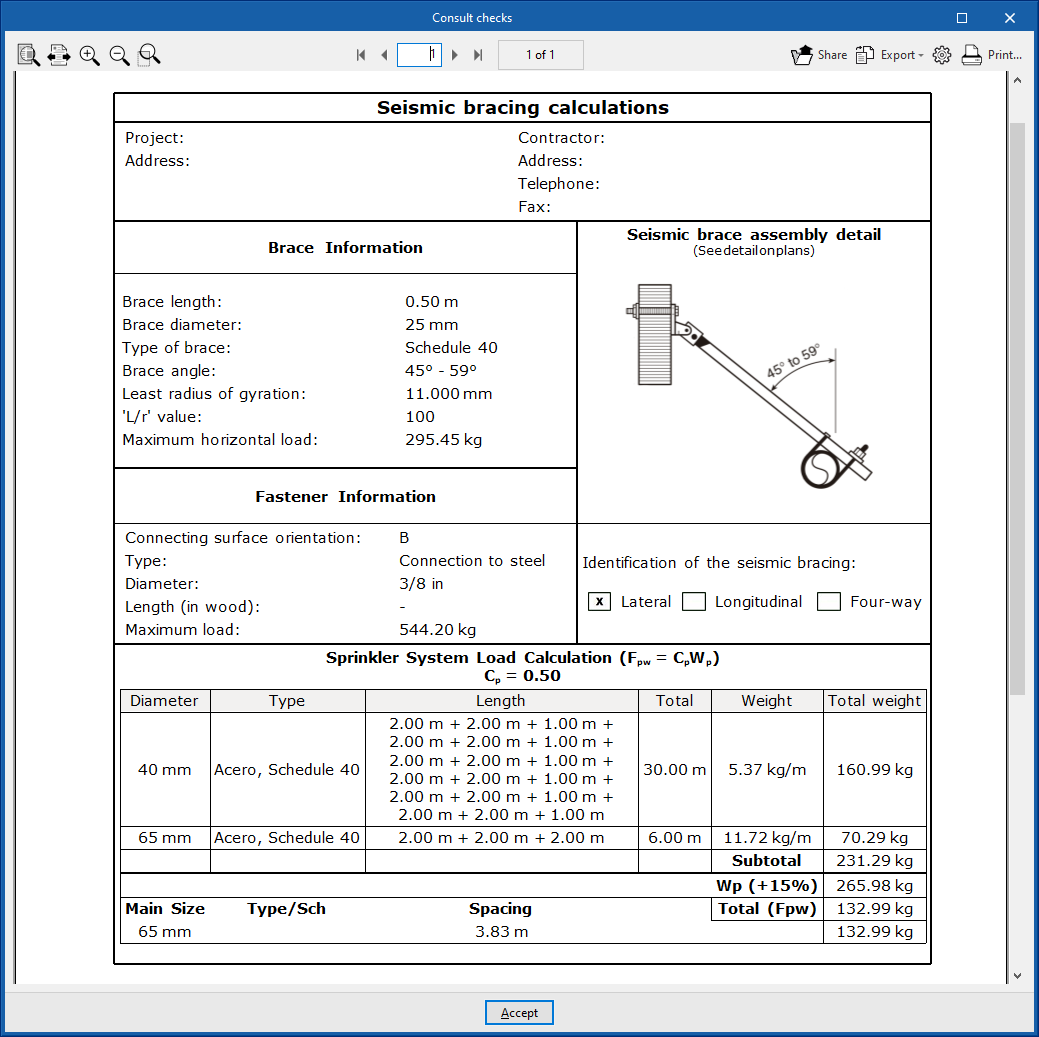
Also, by clicking on the "Consult checks" option, a complete data sheet with the data, the detail plan and the analysis results of the selected bracing can be obtained.
Assign
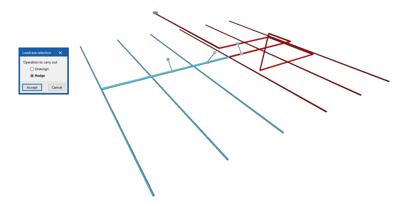
Assigns or unassigns pipes of the fire extinguishing system to certain seismic bracing.
When clicking on a seismic brace, a dialogue box appears where users choose whether they wish to "Assign" or "Unassign" pipes to it. After accepting, the program lights up the pipes that are already assigned to it or those that are not yet assigned, depending on the selected operation. This way, the desired pipes can be selected to complete the operation.
Editing tools
Within the "Installation" tab, in the "Edit" group of the main toolbar, are the following editing tools:

These options allow the following editing operations to be performed on the elements entered in the model:
| Edit | Edits the parametric properties of the selected element in the model. | |
| Assign | Assigns the parametric properties of the selected element to other elements. | |
| Delete | Deletes a previously entered element. | |
| Copy | Creates a copy of one or more elements. | |
| Move | Moves an element or a node of an element. | |
| Rotate | Rotates an element around the displayed axis when using the option. | |
| Move a group of elements | Moves a group of elements. | |
| Rotate a group of elements | Rotates a group of elements around the axis defined by two points. | |
| Symmetry (copy) | Copies a selection of elements with symmetry with respect to a vertical plane defined by two points. | |
| Symmetry (move) | Moves a selection of elements with symmetry about a vertical plane defined by two points. | |
| Measure lengths on plan | Measures lengths and angles between points defined in the model. If a closed outline is selected, it also indicates the area. | |
| Extend/trim element | Extends or trims a pipe with respect to a reference pipe. The former serves as a reference, while the latter is lengthened or shortened after using the option. | |
| Extend/trim to intersection | Extends or trims two selected pipes to their intersection point. |
Analysing, checking and designing
Within the "Installation" tab, in the "Analysis" group of the main toolbar, there are options for analysing, checking and designing the elements in the model:

The program uses the EPANET 2 analysis engine (developed by the Water Supply and Water Resources Division of the National Risk Management Research Laboratory) to perform the hydraulic analyses required for the design of sprinkler and fire hydrant networks. The use of EPANET allows an accurate analysis result to be obtained, valid for compliance with any of the codes available in the program or the configuration that is entered manually.
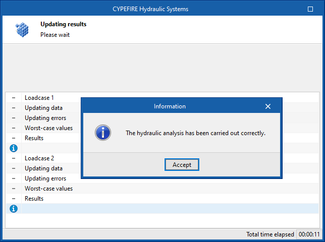
Update results
This will analyse the entered system according to the latest changes, including all design scenarios, update the calculated parameters in the elements and check if they are within the permitted ranges.
The result is a direct display with error or warning messages about the parts of the system that have a problem or fail a check, as well as the results and reports available after the analysis in the "Checks" section of the editing panel of the elements that have this feature.
Design
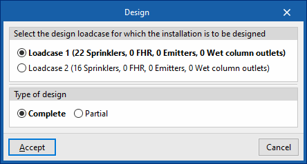
Designs the network according to the indicated loadcase, automatically selecting the size of the pipes.
The "Design" panel has two options:
- Select the analysis scenario for which you want to design the system
Select one of the defined analysis scenario in order to carry out the design. The number of sprinklers, fire hose reels, emitters and wet riser outlets assigned to the scenario is shown in brackets. - Type of design
- Total
The entire job is designed. - Partial
Only the design of the part of the system downstream of a given control point is carried out. To do this, after accepting the panel, a "Control point" previously entered in the installation must be selected.
- Total
In the editing panel of some elements such as tanks, the program can also be used to design the element with the corresponding tool in the lower right-hand area.
| Note: |
|---|
| The analysis and design of an automatic sprinkler system can be quite complex. All the hydraulic analysis requirements that comply with the different applicable standards make the selection of the size of the pipes to be used one of the most complex tasks in the system design. The design tool can be configured from "Design criteria" under "Code configuration". From this panel it is possible to edit the pipe diameters to be used in the design and the maximum number of sprinklers that each diameter can feed until jumping to the next diameter. The "Design" tool will launch the diameter selection process and then the hydraulic analysis. This selection and hydraulic analysis process will be finished if no errors are found when comparing the results obtained with the requirements defined in the project options. Otherwise, the process shall be repeated until valid diameters are selected to comply with the selected standard or the defined configuration. |

Consult checks
Consults the checks carried out in the last analysis performed on the job. After selecting the option, users can click on the elements in the system to directly access the list of checks carried out on the same.
If any changes have been made to the elements in the system, the "Update results" option must be used so that the program will update the results displayed.
Show/Hide results
If this option is activated, the elements in which an error has occurred are highlighted. By hovering the cursor over these elements, the message describing the error can be displayed.
Collision analysis
During the design process, after performing the hydraulic analysis, the program analyses the geometry of the system's elements and architectural model elements, such as beams and columns, and performs a collision analysis between them. In this way, it can show errors with the location of the points in the model where these problems occur to help the user with the system layout.
Results output
Checking results on screen
After carrying out the analysis, the program displays the results in the tooltip or information text that appears when the cursor is hovered over an element in the system. To do this, the "Show information texts" option in the top right-hand toolbar must be checked.

Checks in the editing panel
The program also displays the "Checks" of the last analysis performed in the corresponding section of the editing panel for each element, as well as its compliance status.

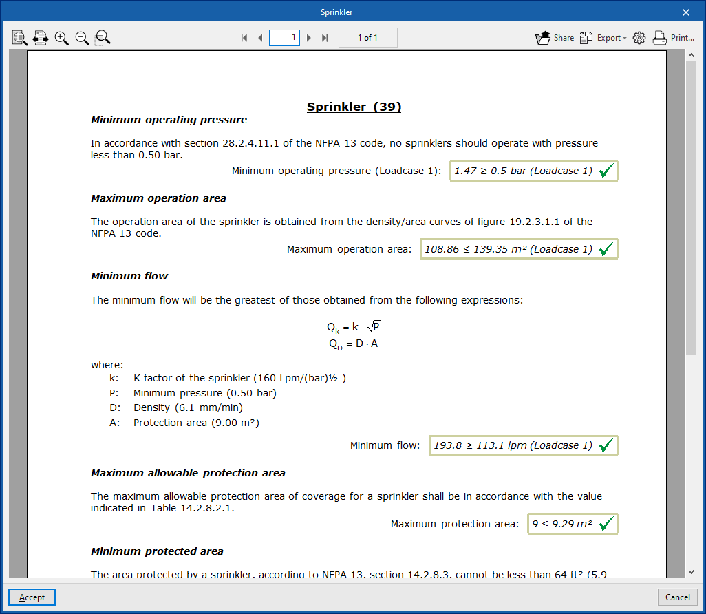
Check reports per element
By editing some elements, the report of specific checks can be consulted through the corresponding option.
In these reports, the analysis expressions and the description of each check, as well as the analysed quantities and the set value limits are detailed.
Graphical analysis of the results
Using the "Graphical analysis of the results" option in the "Calculation" group of the main toolbar, the calculated values of different quantities are displayed with the spans of the water distribution system marked with colours.
By default, the program displays the minimum and maximum values of each factor obtained in the calculation for the entire system. However, the colour scale can be adjusted according to the specific ranges of minimum and maximum values defined in the corresponding dialogue box.
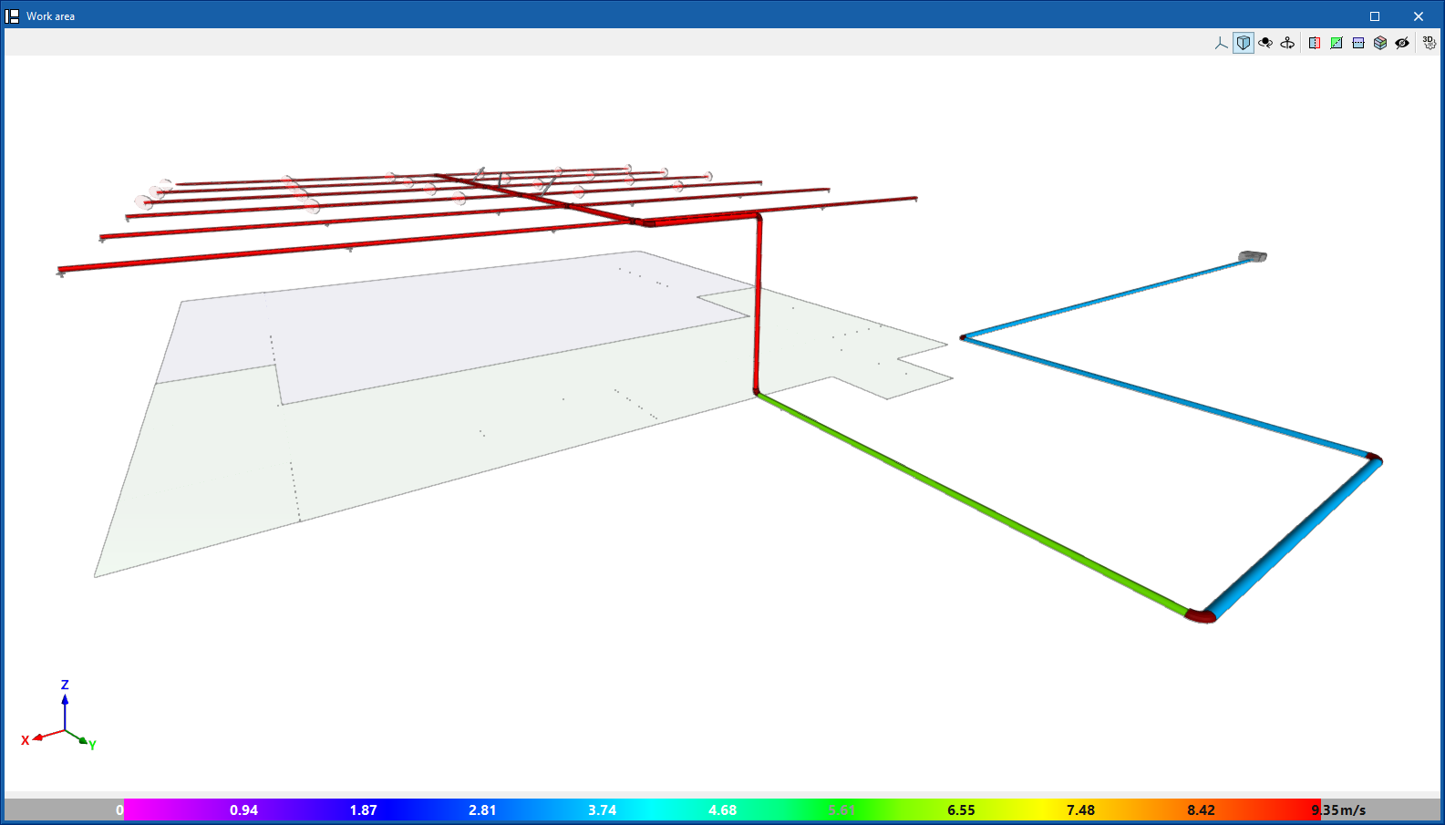
The results available in the graphical analysis of results are as follows:
- Flow rate
- Velocity
- Pressure loss
- Length
- Head

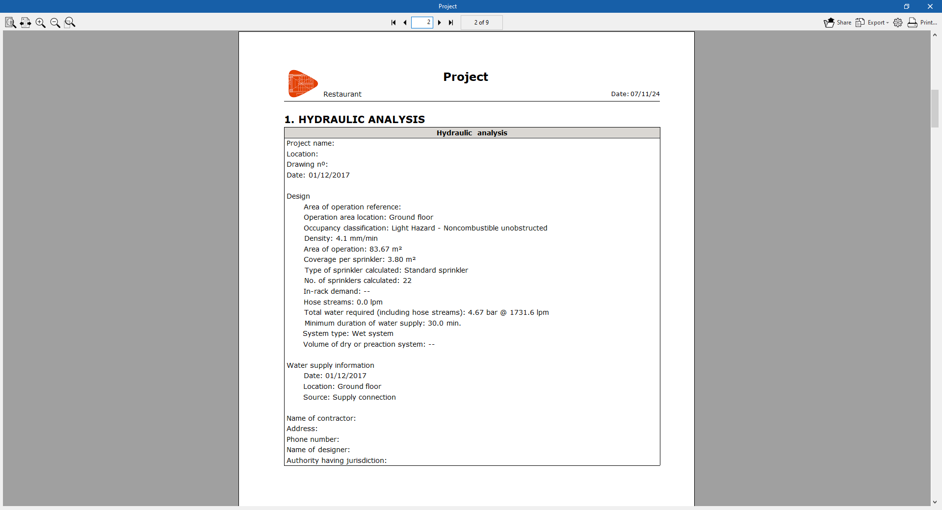
Job reports
The program can also print the following reports directly with the printer or generate HTML, PDF, TXT, RTF or DOCX files:
The reports are obtained via the "Reports" option in the "File" menu or via the specific option at the top left of the interface.
- Project
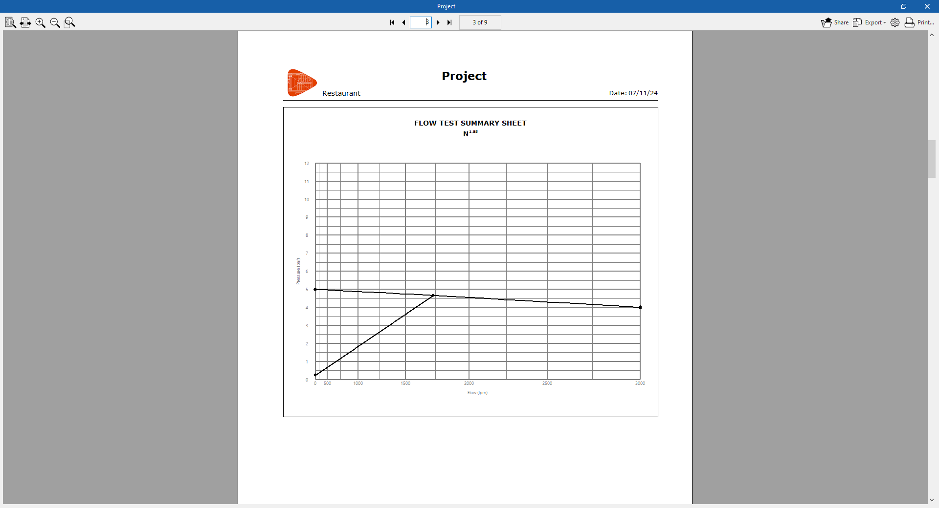
Displays a project report that includes the following sections:- Index
- Hydraulic analysis
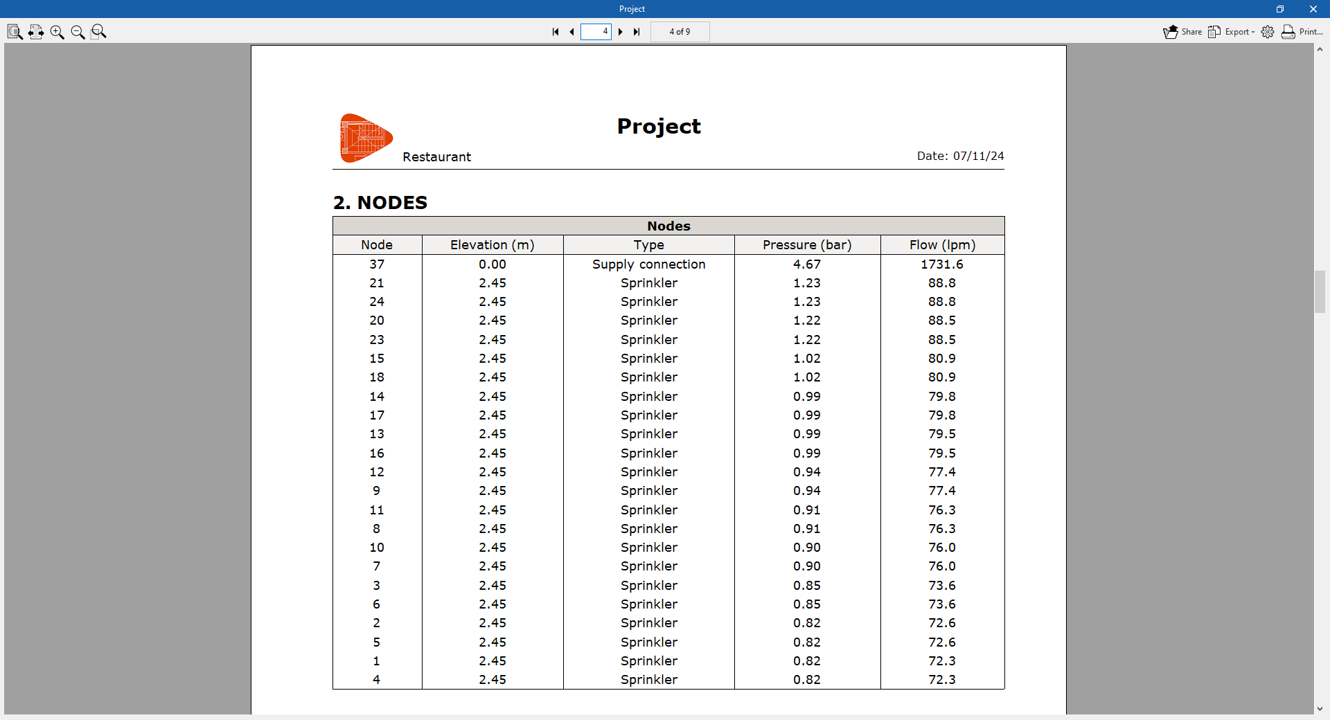
This includes the general data of the project and the flow/pressure graph of the system. - Nodes
- Node reference.
- Elevation of the node.
- Type of node.
- Flow in the node.
- Pressure in the node.
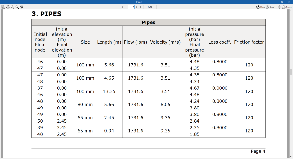
- Pipes
- Reference of the initial and final nodes.
- Initial and final elevation.
- Diameter.
- Length.
- Flow and velocity of the flow.
- Initial and final pressure.
- Loss coefficient.
- Friction factor.
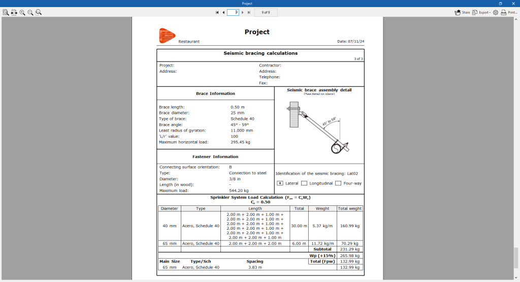
- Seismic bracing
Justification sheets of the seismic bracings provided.

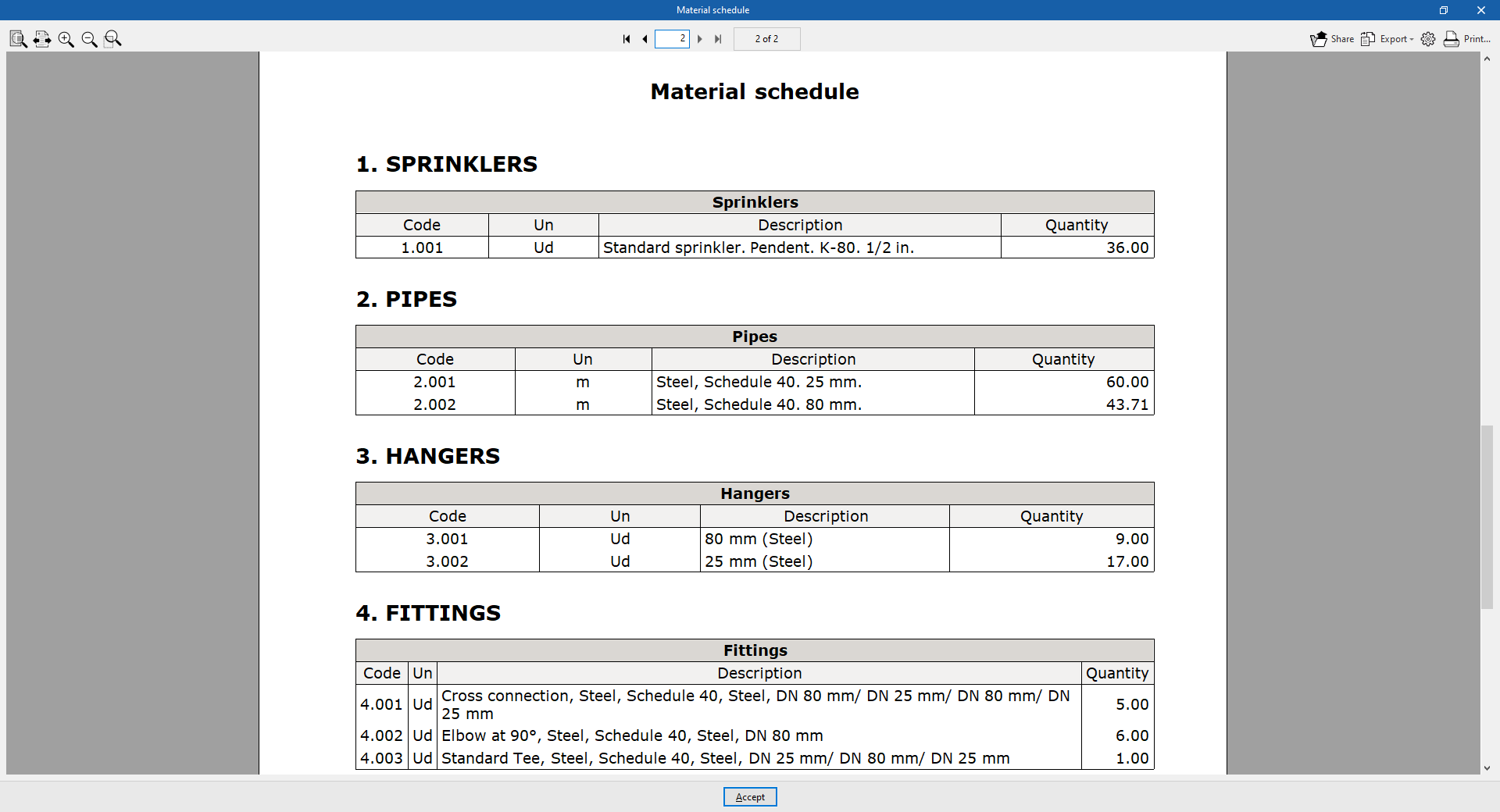
- Material schedule
Displays the material schedule with the measurement of the elements arranged in the system.
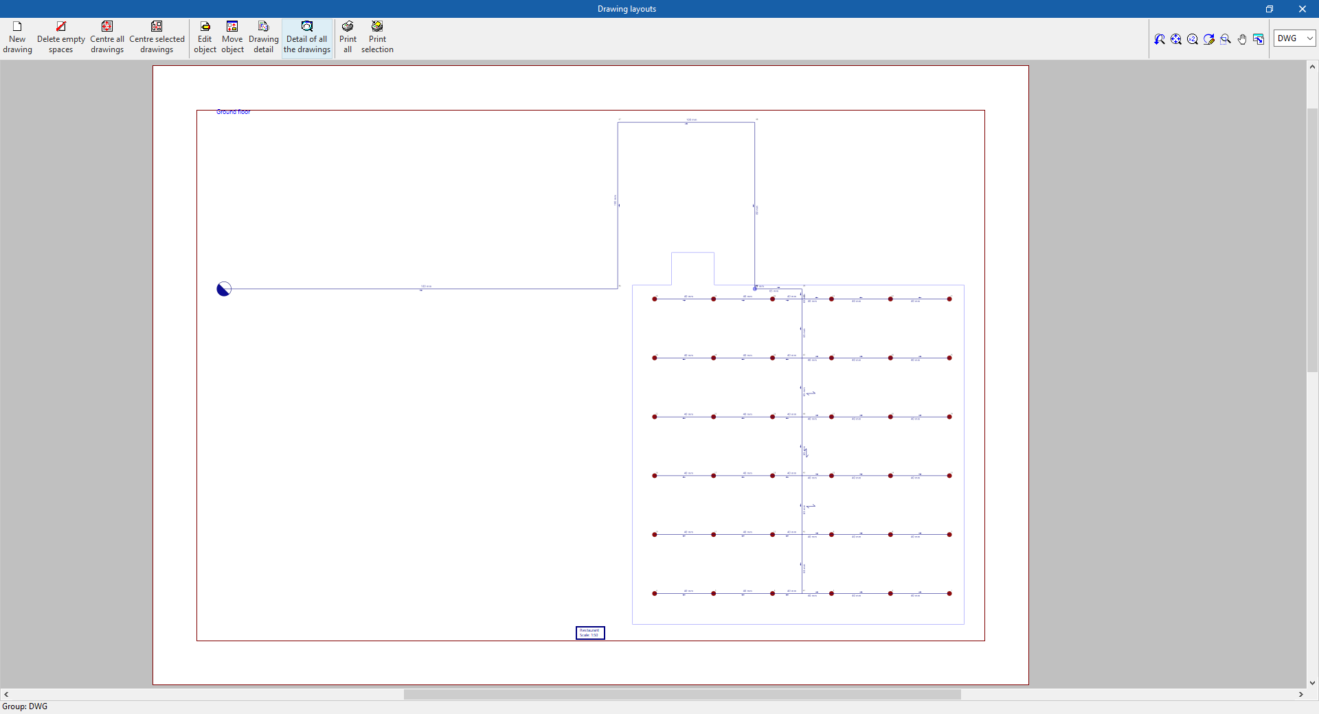
Drawings in DWG, DXF or PDF format
This allows users to print the job drawings of the single-line diagram on any graphic peripheral that is configured on the computer, or to create DWG, DXF or PDF files.
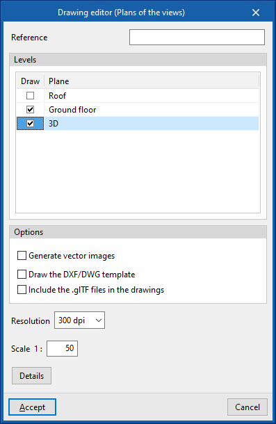
The following options can be configured when editing the drawing:
- Views to be drawn
- Options
- Generate vector images
- Draw the DXF/DWG template
- Include .glTF files in drawings
- Resolution
- Scale
- Details
The drawings can be obtained through the specific option at the top left of the interface or through the "Drawings" option in the "File" menu.

Results of the "Bill of quantities" tab
If the work is completed in the "Bill of quantities" tab, the following documents can be obtained from the program:
- Exporting the bill of quantities in FIEBDC-3 (BC3) format.
- Bill of quantities reports (in HTML, PDF, TXT, RTF or DOCX format).
Files supported by BIMserver.center
When a project is exported to the BIMserver.center platform, a 3D model is automatically exported in GLTF format for the integration of the installation model in the Open BIM project, allowing its visualisation:
- On the online platform;
- In the BIMserver.center app for iOS and Android.
- In virtual reality and augmented reality;
- In other CYPE programs.
Integration into the BIMserver.center platform
Many of CYPE's programs are connected to the BIMserver.center platform and allow collaborative work to be carried out via the exchange of files in formats based on open standards.
Please note that, to work on BIMserver.center, users can register on the platform free of charge and create a profile.
When accessing a program connected to the platform, the program connects to a project in BIMserver.center. This way, the files of the projects that have been developed collaboratively in BIMserver.center are kept up to date.

| More information: |
|---|
| For further details related to using CYPE software via the BIMserver.center platform, please click on this link. |
Options available in CYPEFIRE Hydraulic Systems
In the "BIMserver.center" group of the main toolbar, under the "Installation" tab, there are features for using the program together with other BIMserver.center tools:

Update
Update information contained in models previously imported into the project or import new models if desired.
In the update process, just like the process of creating a new job, the spaces in the BIM model can be read and assigned to one of the types of spaces defined in the project options. This way, the program generates the spaces automatically or updates them according to the latest changes.
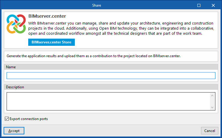
Share
Exports the system information developed with the program to BIMserver.center to share it with other users.
During the export process, information related to the identification of the files to be exported can be defined:
- Name
- Description