As of version 2024.a, the following applications are also available in Japanese:
- CYPE Architecture
- IFC Uploader
- Open BIM Analytical Model
- Open BIM Layout
- Open BIM Model Checker
- Open BIM Site
- Plugin Open BIM - Revit

A recent post on the CYPE blog detailed the improvements of the Open BIM - Revit Plugin incorporated in version 2023.e, focusing on the linking of IFC files and the information contained in elements, which can be recognised as belonging to Revit's own categories and which, therefore, allows tagging or listing actions to be carried out in planning tables.
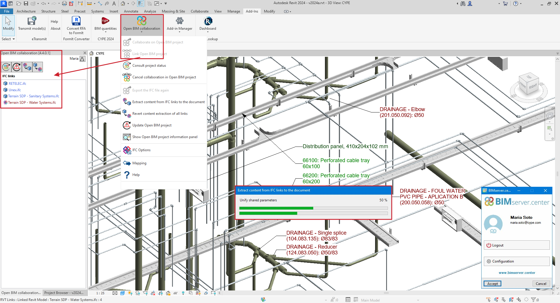
Version 2024.a of the plugin includes a notable improvement from a user experience point of view: the extraction of content from IFC links, as well as compatibility with Revit 2024.
The new version makes it possible for users to convert the linked IFC model into a set of individual objects (DirectShape), which means that these objects can be deleted or their position can be changed, and the associated element parameters can be modified. Furthermore, linking to native Revit categories allows filtering, tagging and listing in tables (as was already the case with linked IFCs).
For the analysis and documentation of the models, the conversion process adds a significant advantage: the unifying of shared parameters. Linking IFC models to a Revit project requires the association of individual IDs to each IFC property or attribute; the consequence of this process is that the same attribute/property receives different IDs in different links, which makes it necessary to define the specific shared parameter file for each operation to be performed on each of the linked models. By extracting the content of the IFC links, this tedious operation is no longer necessary; the plugin takes care of unifying the shared parameters so that users are not forced to maintain and manage a set of shared parameter files (one for each linked IFC model). In other words, the process becomes transparent to users, who only need to be concerned with locating the attribute/property to be listed, by its name.
The conversion process is fully reversible; users can either Extract content from the link to the document or Revert the content extraction of the link. Users can maintain the synchronisation of the different models to the project in BIMserver.center and define this operation either for the federated set of models or individually, for each of them (the status of each link will be shown with a different icon and colour).
Overall, the potential of the new plugin significantly improves the users' experience and allows models present in the project shared on BIMserver.center to be integrated into the Revit file, making coordination and documentation tasks easier. This capability is of particular interest for highly detailed and accurate models generated from the manufacturer's applications, which are free to use.
As of CYPEFIRE Hydraulic Systems version 2024.a, emitters can now be entered.
Emitters allow the hydraulic analysis and hydraulic check to be carried out on any fire extinguishing elements found in a system (sprinklers, fire hose reels, fire hydrants, etc.) without depending on the geometric and hydraulic restrictions of the sprinklers and hydrants that already exist in the program.
To enter an emitter, simply enter the following:
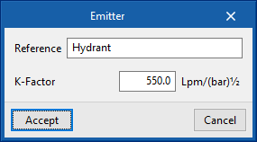
CYPEFIRE Hydraulic Systems does not carry out any checks on the emitters but, thanks to the EPANET calculation engine, it can carry out the hydraulic analysis of the designed system and, on the program interface itself, it allows users to view the flow and pressure data obtained for each of the emitters entered.
With this new feature, CYPEFIRE Hydraulic Systems becomes more versatile. Now, as well as being able to continue to use the predefined elements such as sprinklers or fire hose reels, the emitters can be used to carry out only the hydraulic justification of the desired element.
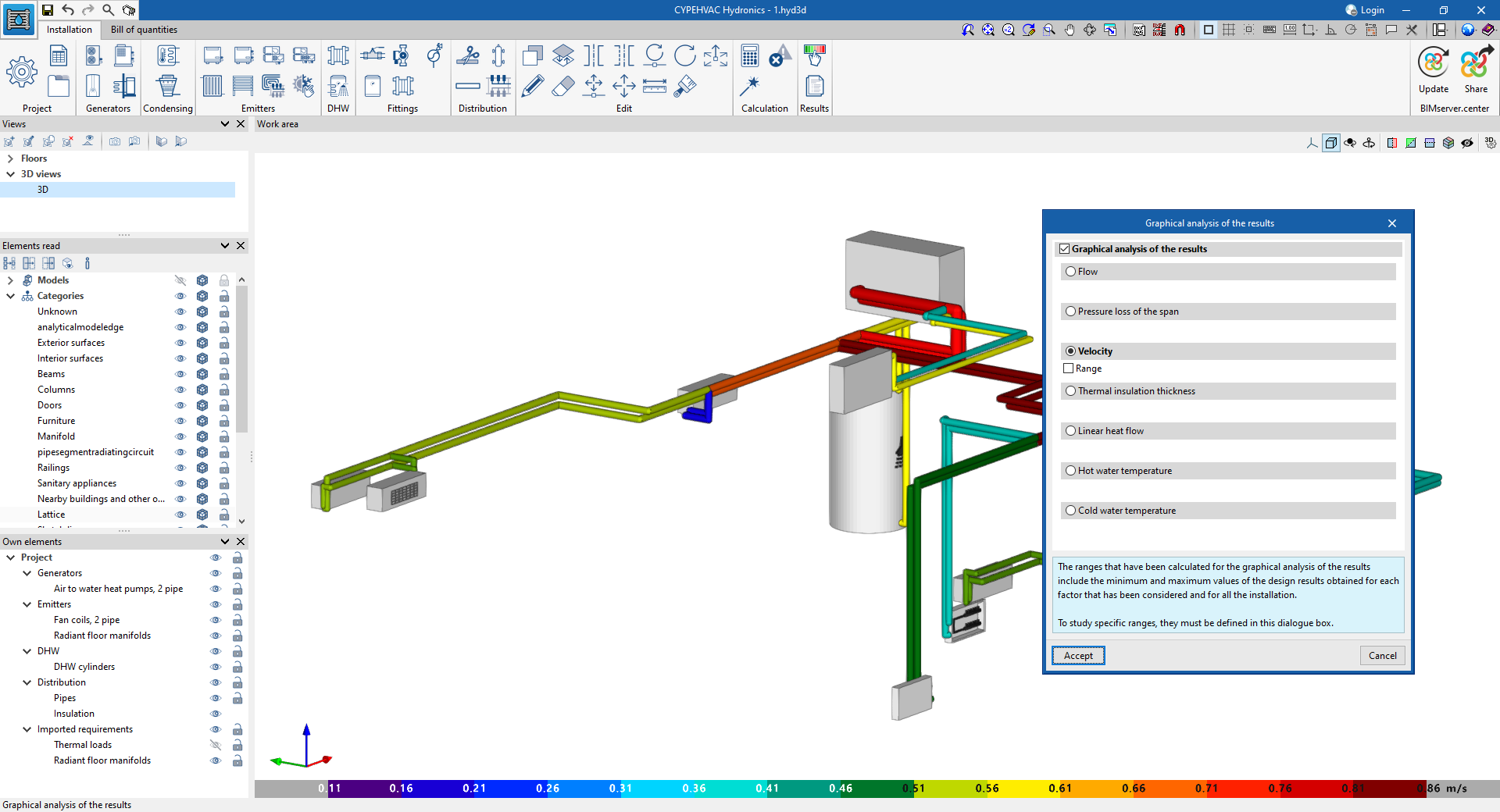
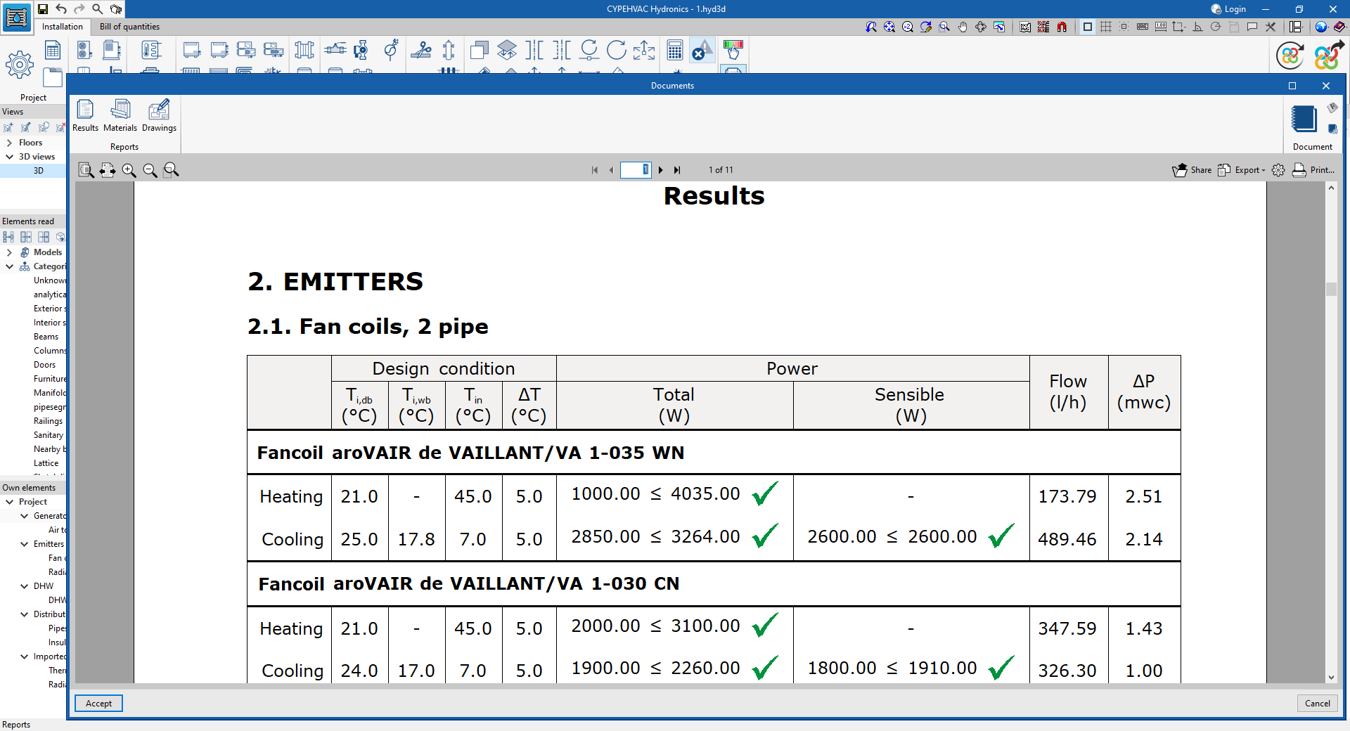
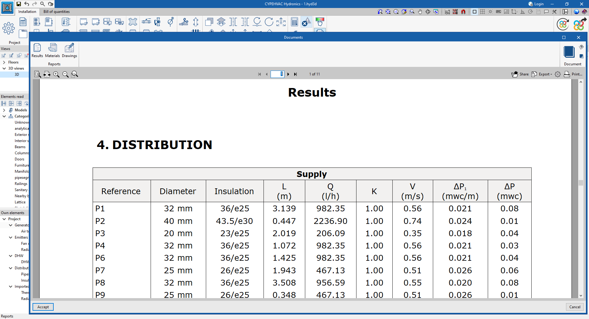
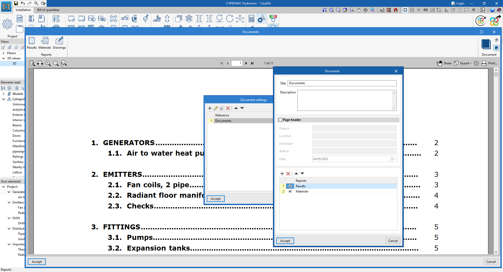
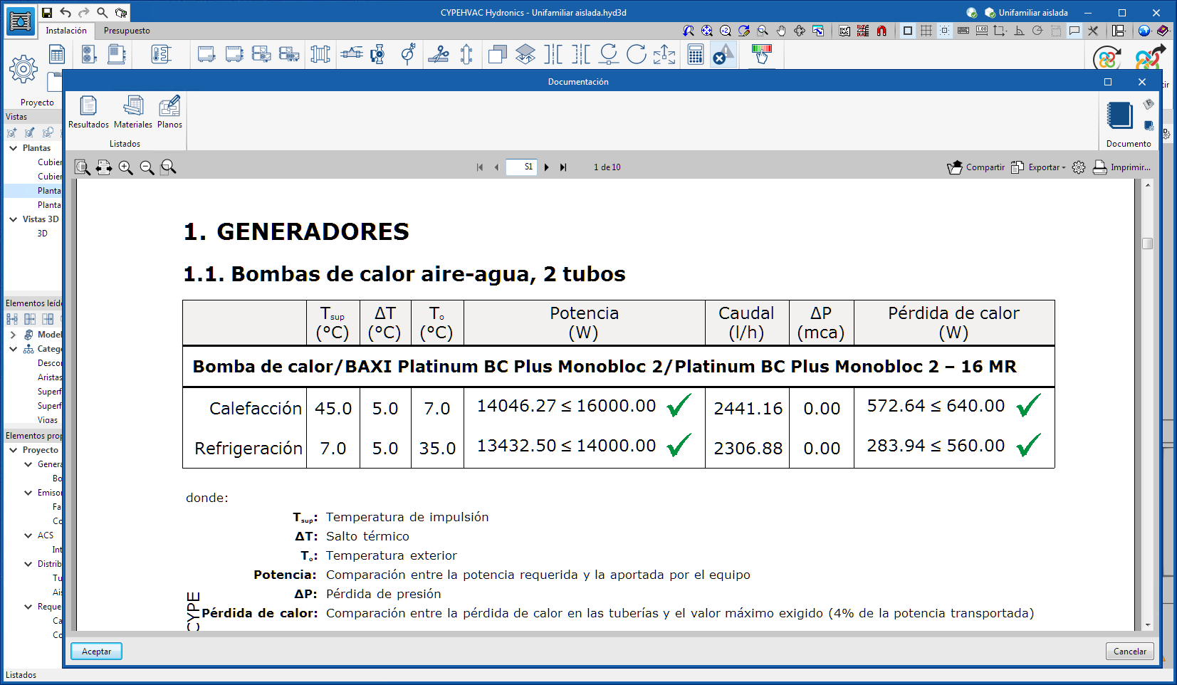
In the previous version (2023.g) a new 3D work environment was implemented in CYPEHVAC. Now, in version 2024.a, reports with the main results of the system calculation and the possibility of configuring the documents generated by the program from the available reports have been included: "Results", "Materials" and "Drawings".
In addition, the "Graphical analysis of the results" tool has been adapted to the new 3D environment for displaying different calculation variables on the system, modifying the colour of the pipe spans depending on the value of the variable.
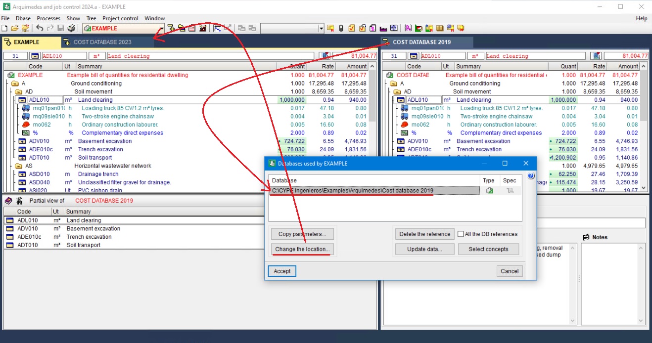
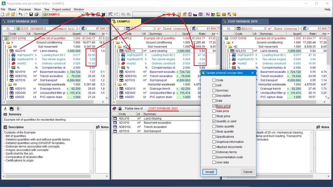
In versions prior to 2024.a, in order to change the reference database and update the prices with references that were external to the previous database, a somewhat non-direct process had to be carried out. Now, with version 2024.a, this process has been made much easier by the implementation of the "Change the location" option in the "Databases used by..." dialogue box.
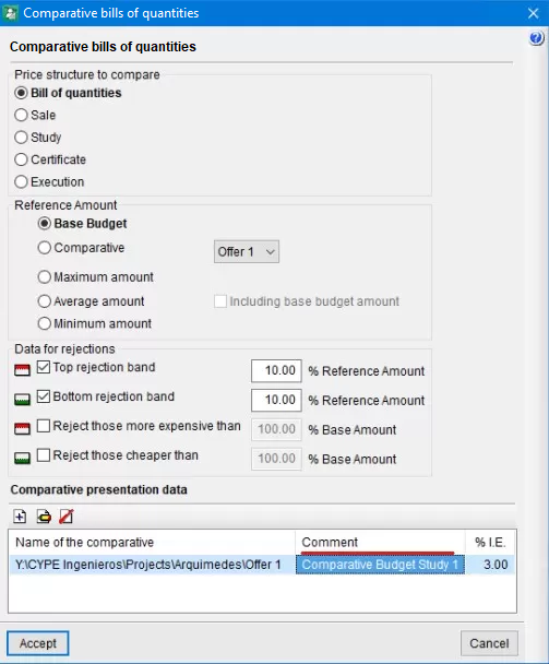
As of Arquimedes version 2024.a, in the "Comparative bills of quantities" dialogue box, the cells of the "Comment" column belonging to the table at the end of this dialogue box (in the "Comparative presentation data" section) can be edited directly.
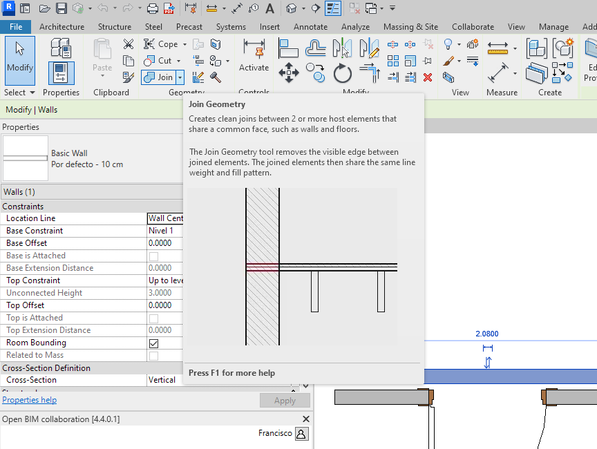
When a multilayer wall is defined in Revit, there are usually two different ways for Revit users to define it. One way is to select a multilayer wall that has already been defined as a family and the other way is to enter as many basic walls with as many layers as the multilayer wall to be entered. In the latter case, users use Revit's "Join Geometry" tool after entering the walls to make the whole wall act as a single unit. In both cases, when an opening is entered in the wall in Revit, it affects all the layers of the multilayer wall and all the walls joined by means of the "Join Geometry" tool.
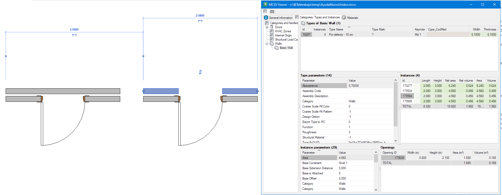
In versions prior to Arquimedes 2024.a, when generating the quantities of these walls using the "MedBIM - Revit Plugin", the composition of the wall was not detected correctly (when it came to deducting an opening in the quantities of the wall) if in Revit the wall had been defined by joining walls that had been entered one by one. For this reason, in the quantities generated by the plugin, the opening was only deducted from one of the walls that made up the complete element. This did not happen when the wall in Revit had been defined as an element with different layers.
As of version 2024.a, the "MedBIM - Revit Plugin" now detects that the wall formed by different walls joined together in Revit is a unit and that the opening affects all the walls joined together in Revit equally.
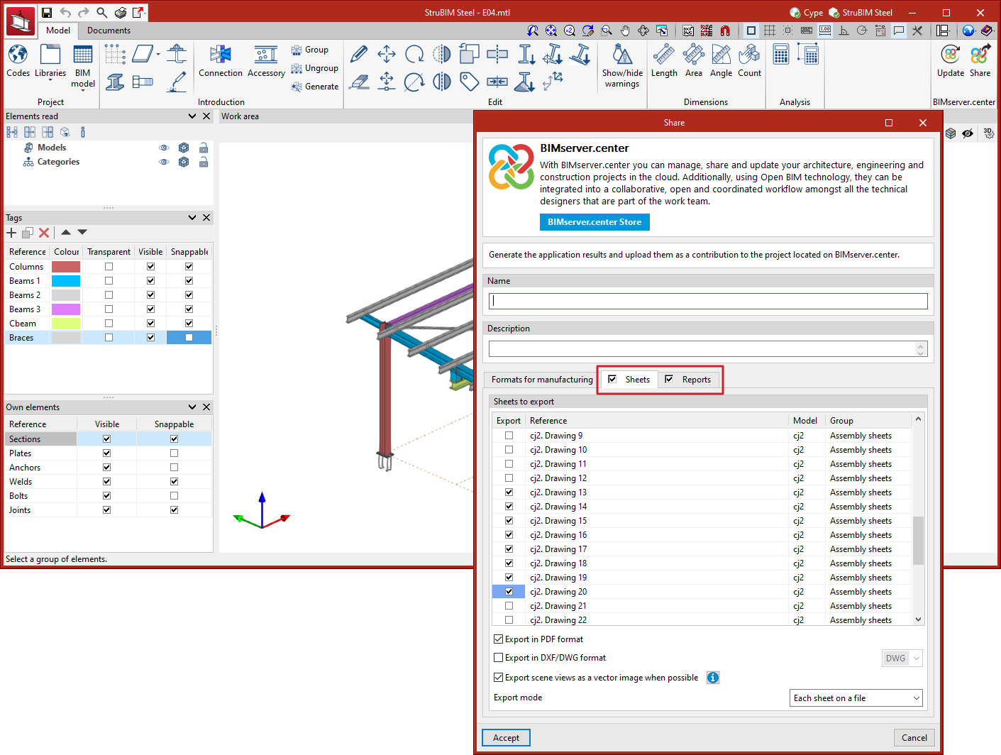
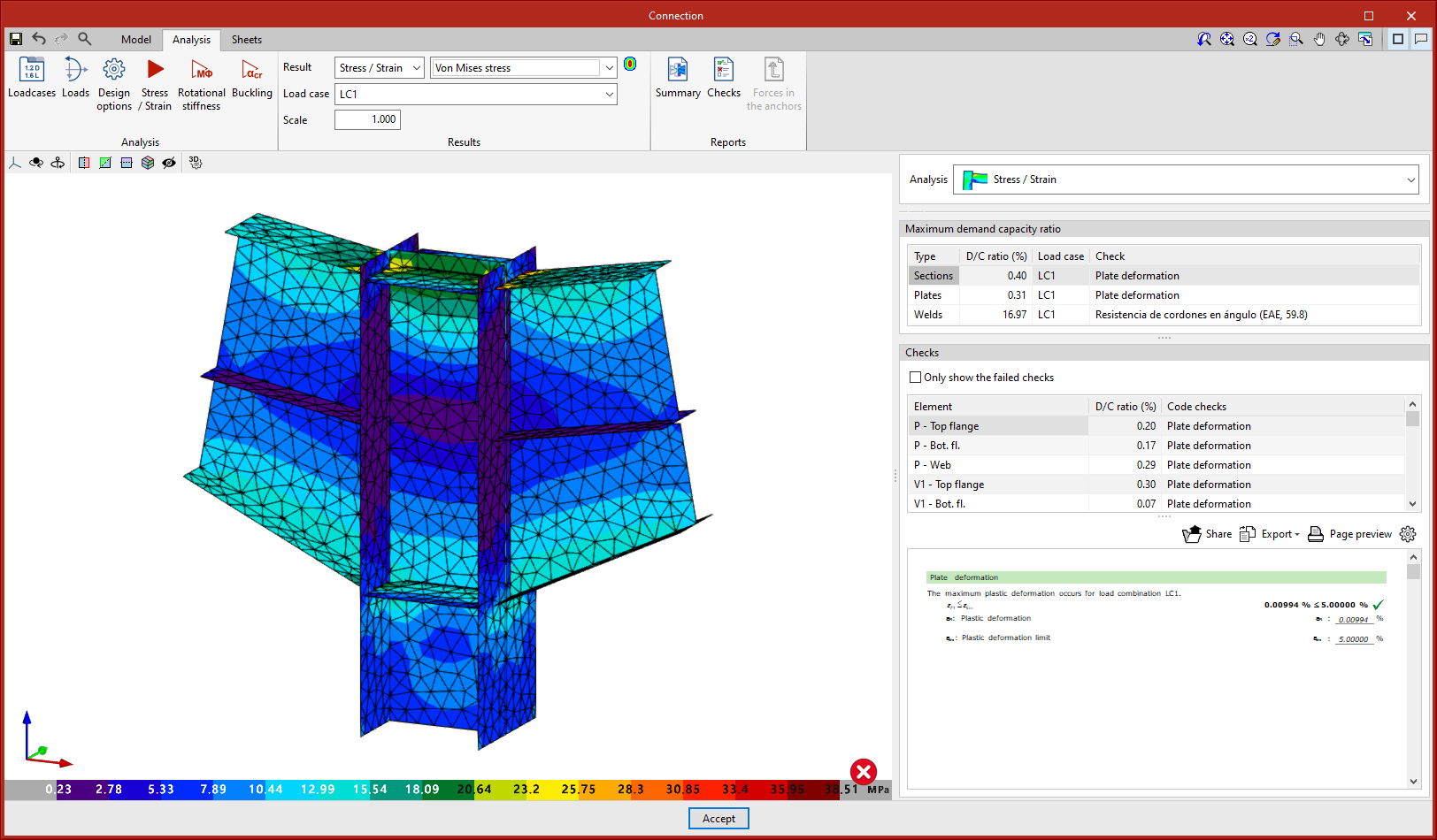
As of version 2024.a, when sharing the model on the BIMserver.center platform, users now have the option to share sheets, quantities reports and connection check reports.
If the "Sheets" tab in the "Share" dialogue box is activated, the selected sheets will be exported in PDF or DXF/DWG format. Another option is to export all sheets in a single file or each sheet in a single file ("Export mode" option located at the end of the "Share" dialogue box).
If the "Reports" tab (next to the "Sheets" tab) is activated, users can also export the connection check report and the quantities report.
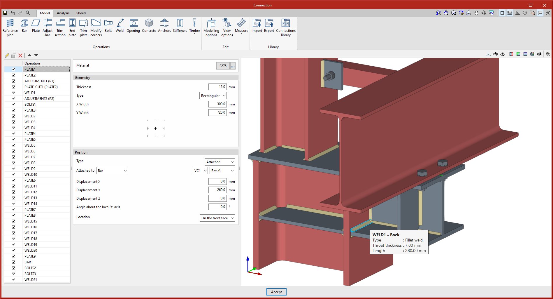
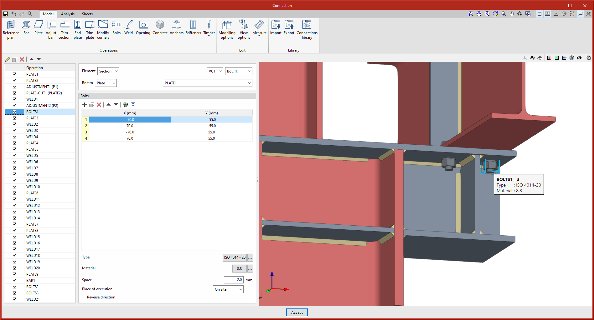
New data has been added to the information tags that are displayed on screen when the cursor hovers over the connection elements:


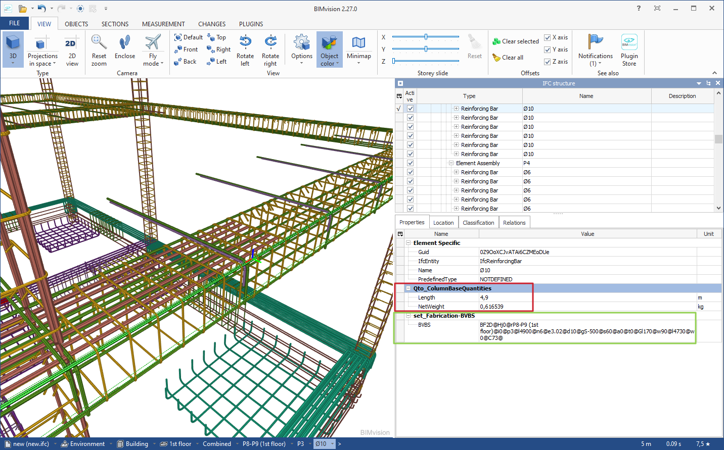
In StruBIM Rebar version 2024.a, new options for exporting to IFC format have been implemented. In the "Configuration" dialogue box (top toolbar > "General data" > "Configuration") the following options are available:
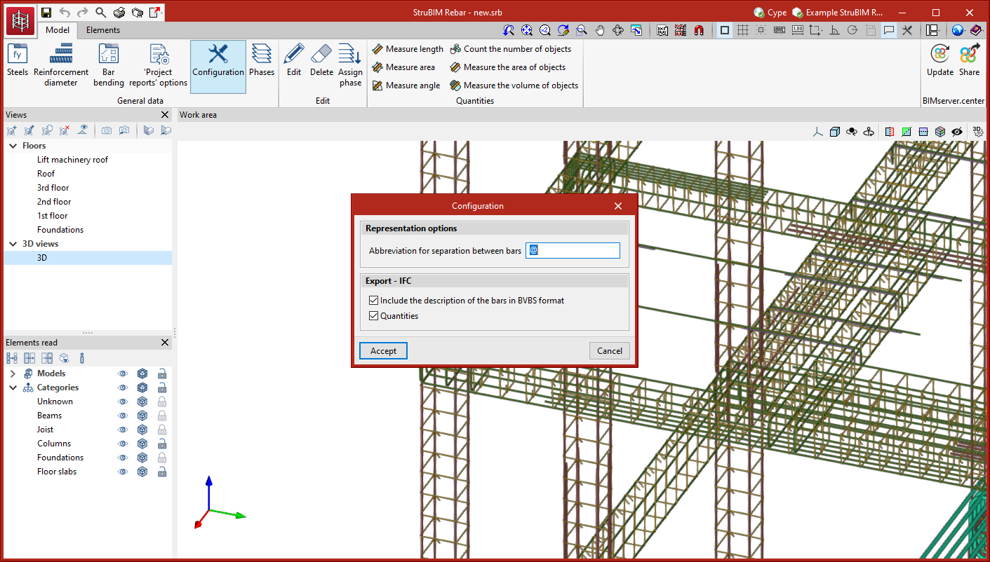
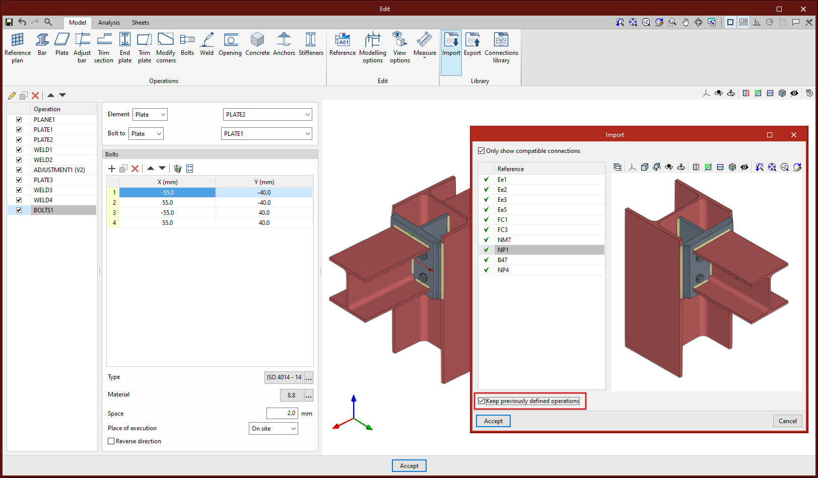
Keep previously defined operations
Up until version 2024.a, when importing a library connection, the list of previously defined operations was cleared. As of version 2024.a, users are given the option to keep the previously defined operations when importing a library connection by activating the "Keep previously defined operations" option. This option is disabled by default.
When importing a connection and keeping the previous operations, if there are already operations with similar references, the prefix B, B1, B2, etc. shall be added to the new operations.
This improvement allows users to import the same library connection several times in the same node or to import several different library connections.
Compatible connections
As of version 2024.a, library connections will be compatible and can be imported even if the section types are different, and even if the sections are different with respect to the "continuous" or "non-continuous" section option.
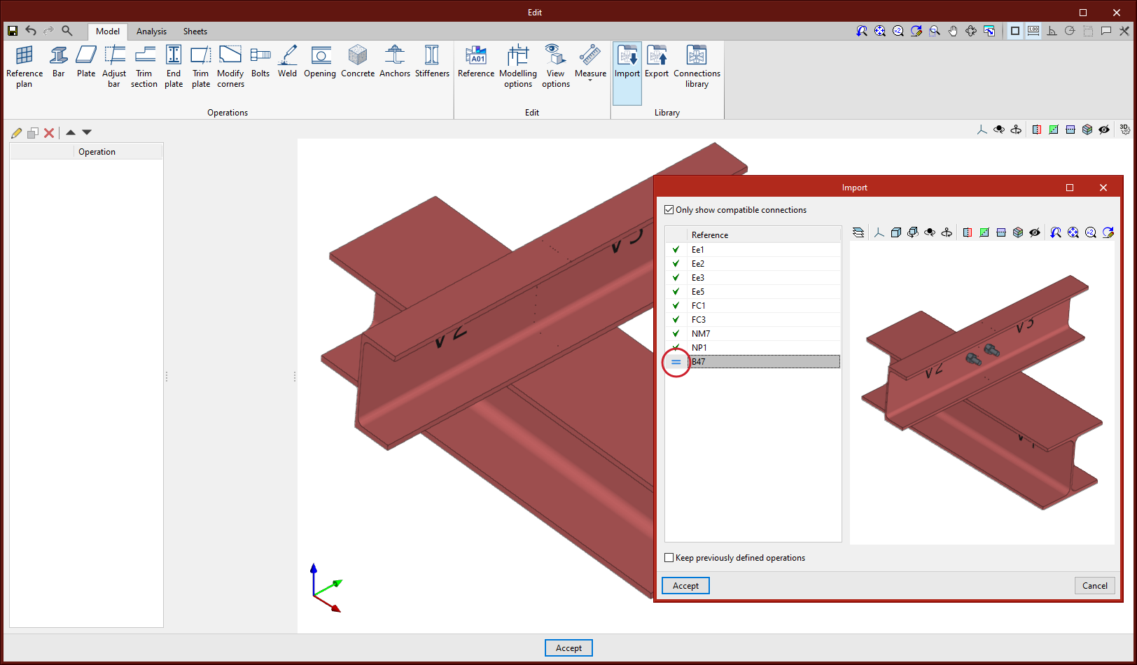
Matching connections
As of version 2024.a, the import panel of library connections will mark connections with a "=" symbol if their section layout is the same as that of the node.
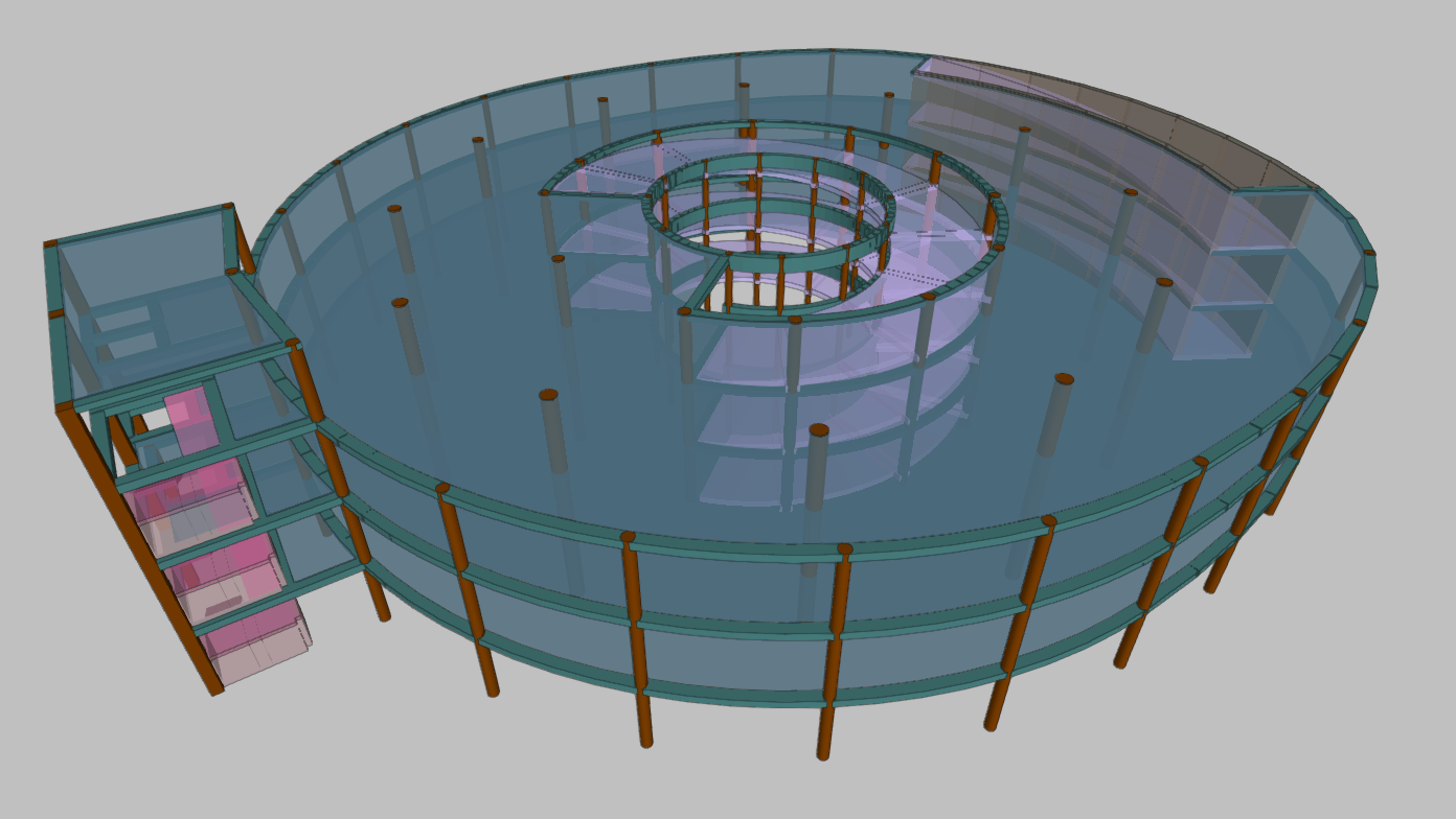
The new CYPECAD ramp module analyses and designs slabs for ramps as isolated elements of the structure. Depending on the geometry, type and layout of the supports and applied gravity loads, the program determines the reactions and applies them as loads on the main structure, resulting in linear loads in the loadcases of dead loads and live loads.
The program resolves ramp cores formed by spans arranged between floors. Each span is made up of one or several elements of one of the types listed below:
As of version 2024.a, elements can be entered at a position defined by polar coordinates with respect to the last marked point. This can be very useful when combined with the "Change the last point" option.
This option can be accessed directly with the "Alt+P" keyboard shortcut.

The portal frame editor has been improved. Starting from this version, if a portal frame has "On-site" type assembly reinforcement, the positive and negative assembly reinforcement can now be extended at the ends of the portal frame.

In CYPECAD version 2024.a, users can set assembly options other than the general ones defined in the job for any desired portal frame. The particular options are taken into account when redesigning the portal frames. When a portal frame has been previously designed with the "At workshop" option if it is changed to "On-site", the program automatically adapts the types of bars arranged in the portal frame. As a result, users can carry out modifications to the reinforcement bars that are not possible with the "At workshop" option but are possible with the "On-site" option.
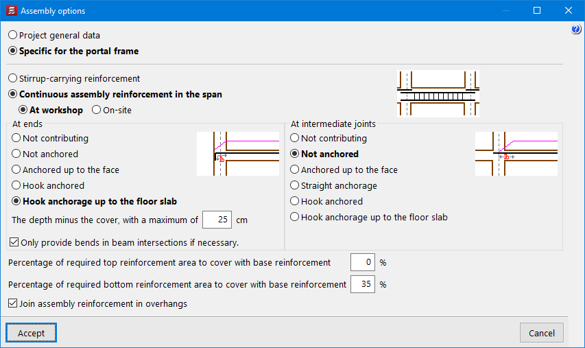
An example would be a portal frame where the top base reinforcement is to be continuous. This is not possible if the selected option is "At workshop" (Fig. 1), but becomes possible when changing to "On-site" (Fig.2).
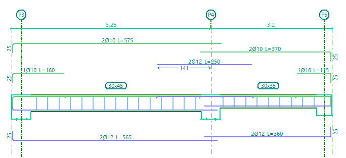
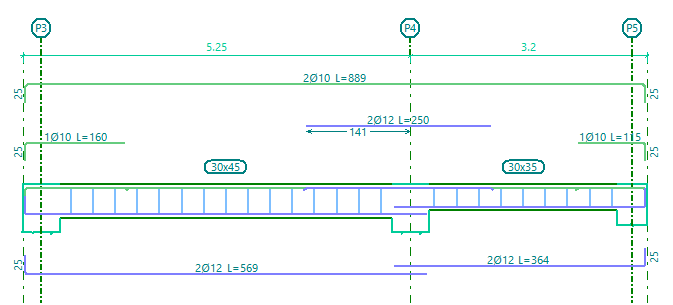
Making changes other than the one mentioned above may require the portal frame to be redesigned in order to obtain reinforcement according to the new options selected. This may happen, for example, when changing from "On-site" to "At workshop".
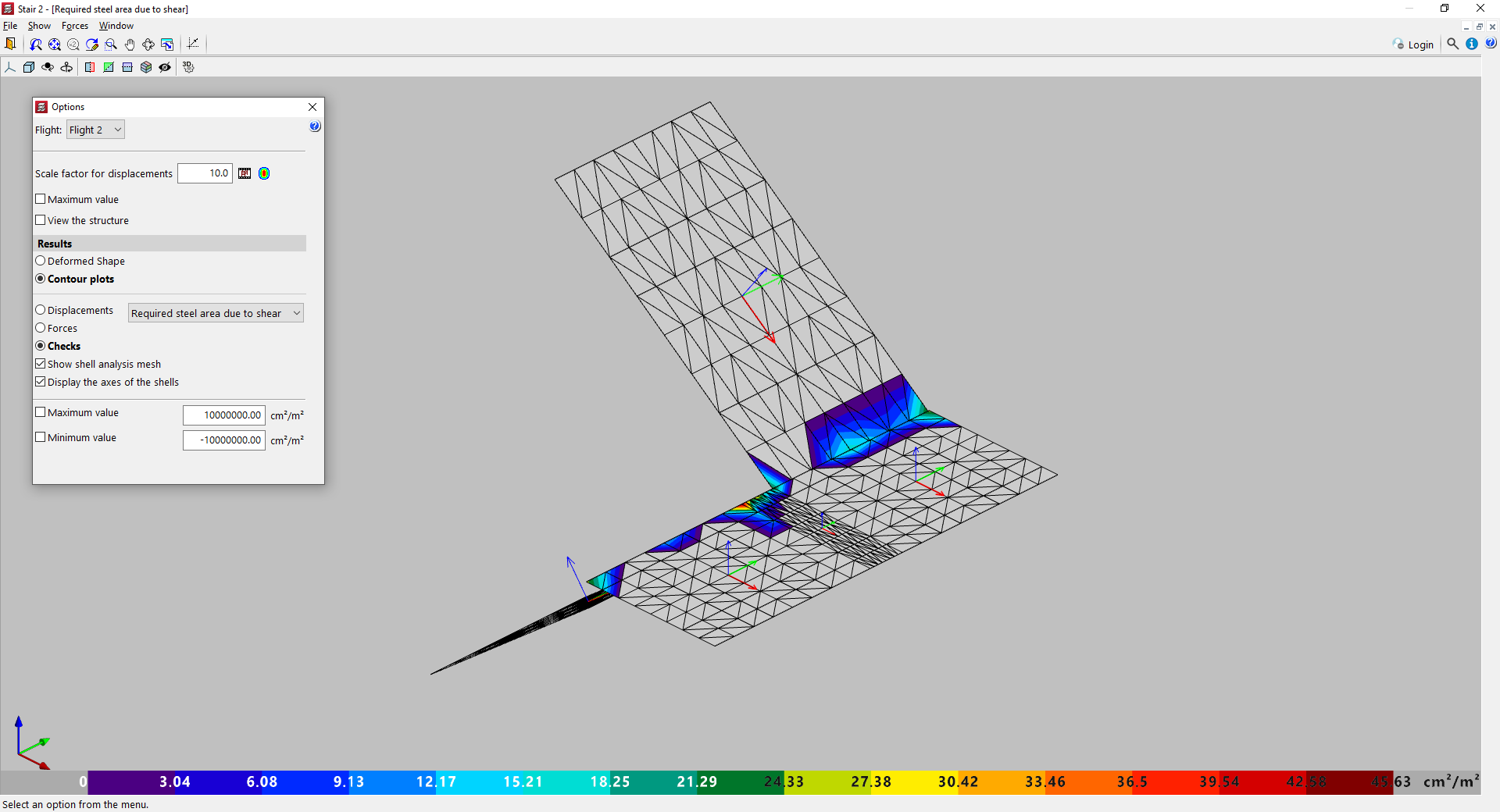
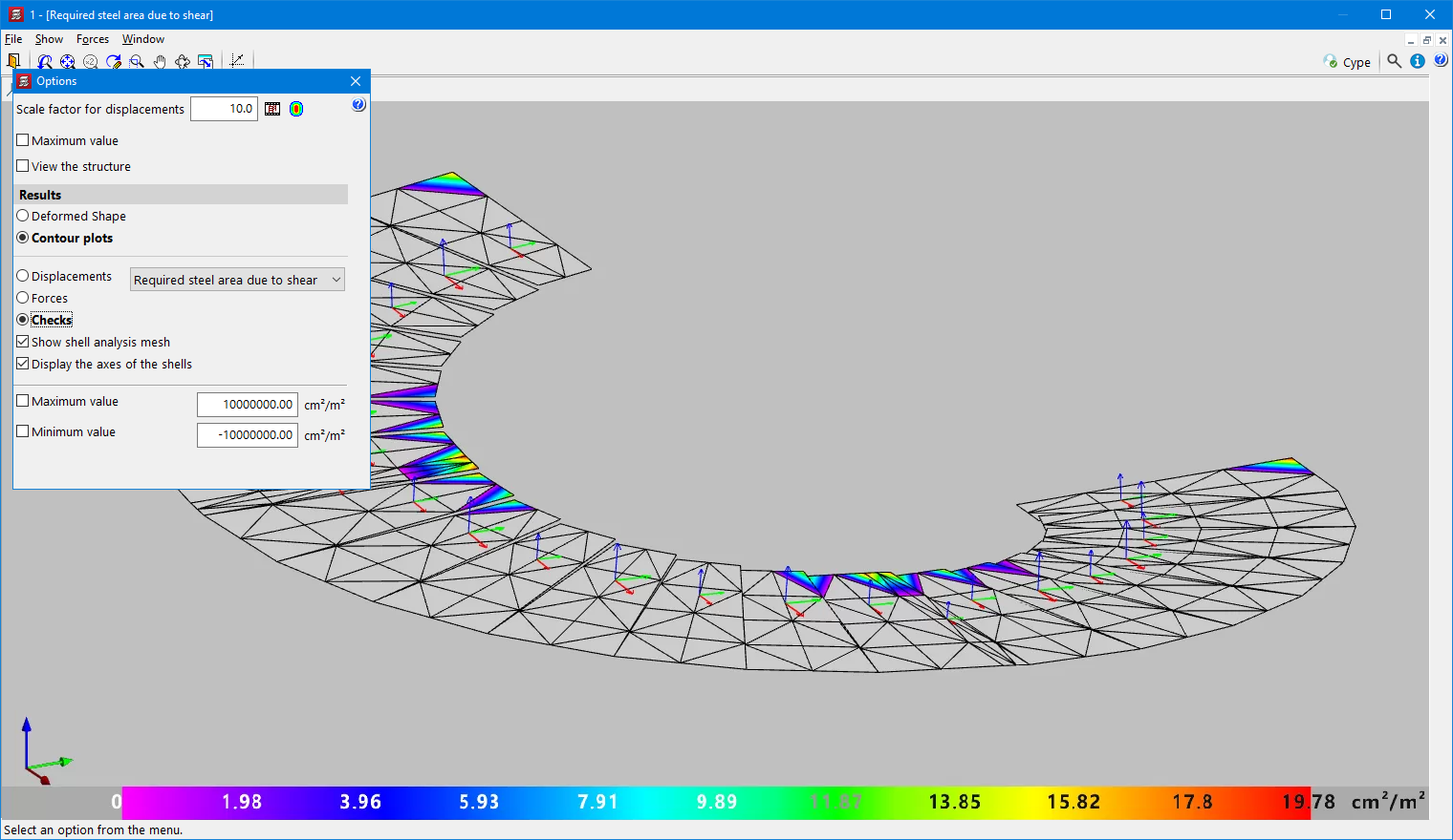
As of version 2024.a, the value of the "Total shear" can be checked in the "Forces" contour plots of a stair core.
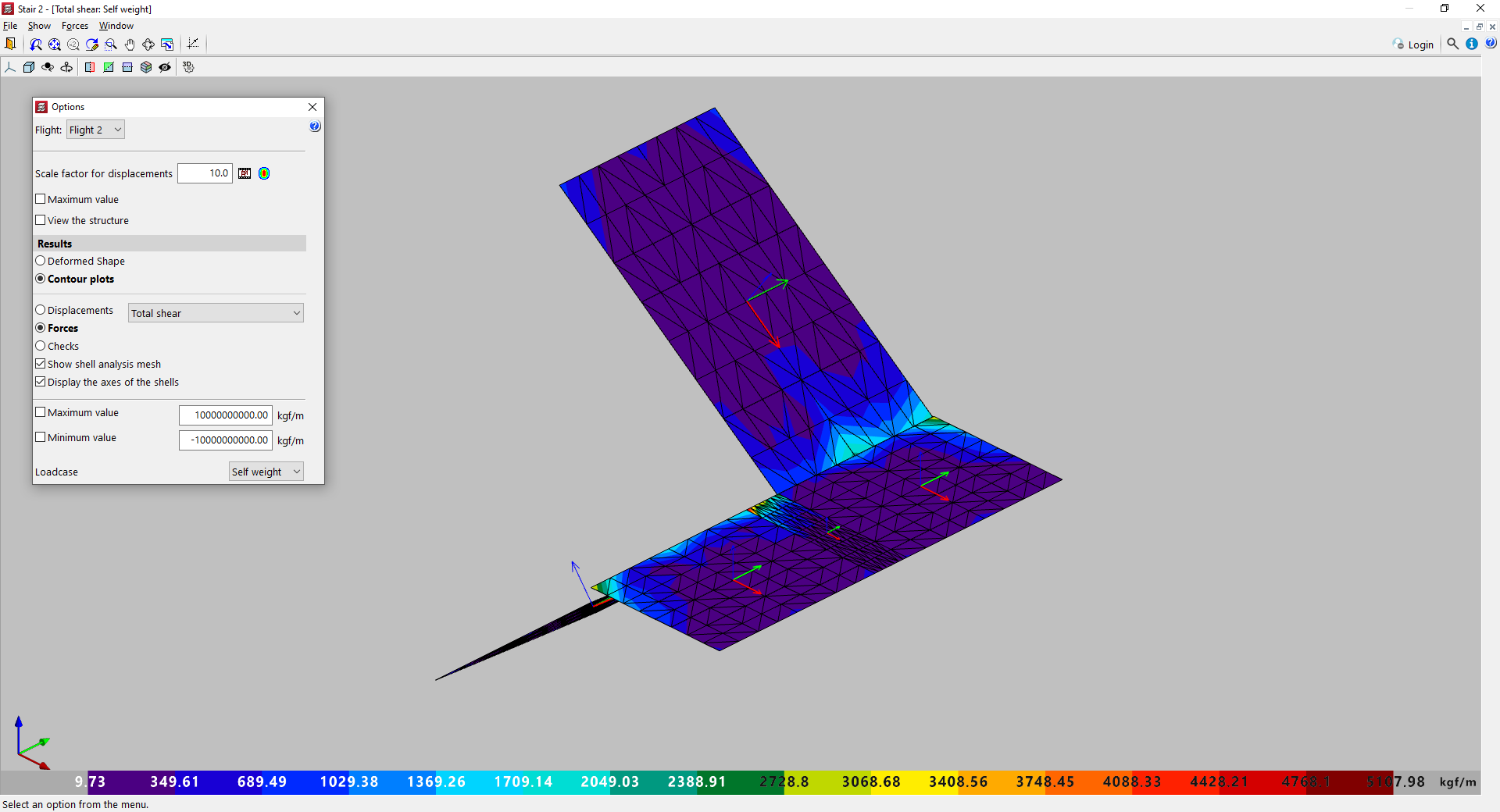
Considering the shear strength criteria of the selected concrete code, users determine whether shear reinforcement is necessary for any area and the ratio that is required. If shear reinforcement is required at any point in a stair core, a warning is displayed. The required ratio, "Required steel area due to shear", can also be checked in the contour plots of a stair core if the "Checks" option is selected.
Since version 2015.a, CYPECAD has had the "Punching shear verification" module. This module makes it easier to verify slabs with and without punching shear reinforcement in accordance with the criteria of the concrete code.
Under the current European standard, Eurocode 2, the resistance provided by punching shear reinforcement is limited. The use of stud systems as punching shear reinforcement of slabs has the advantage of increasing the limit value of the punching shear resistance and avoids the need to increase the depth in many cases.
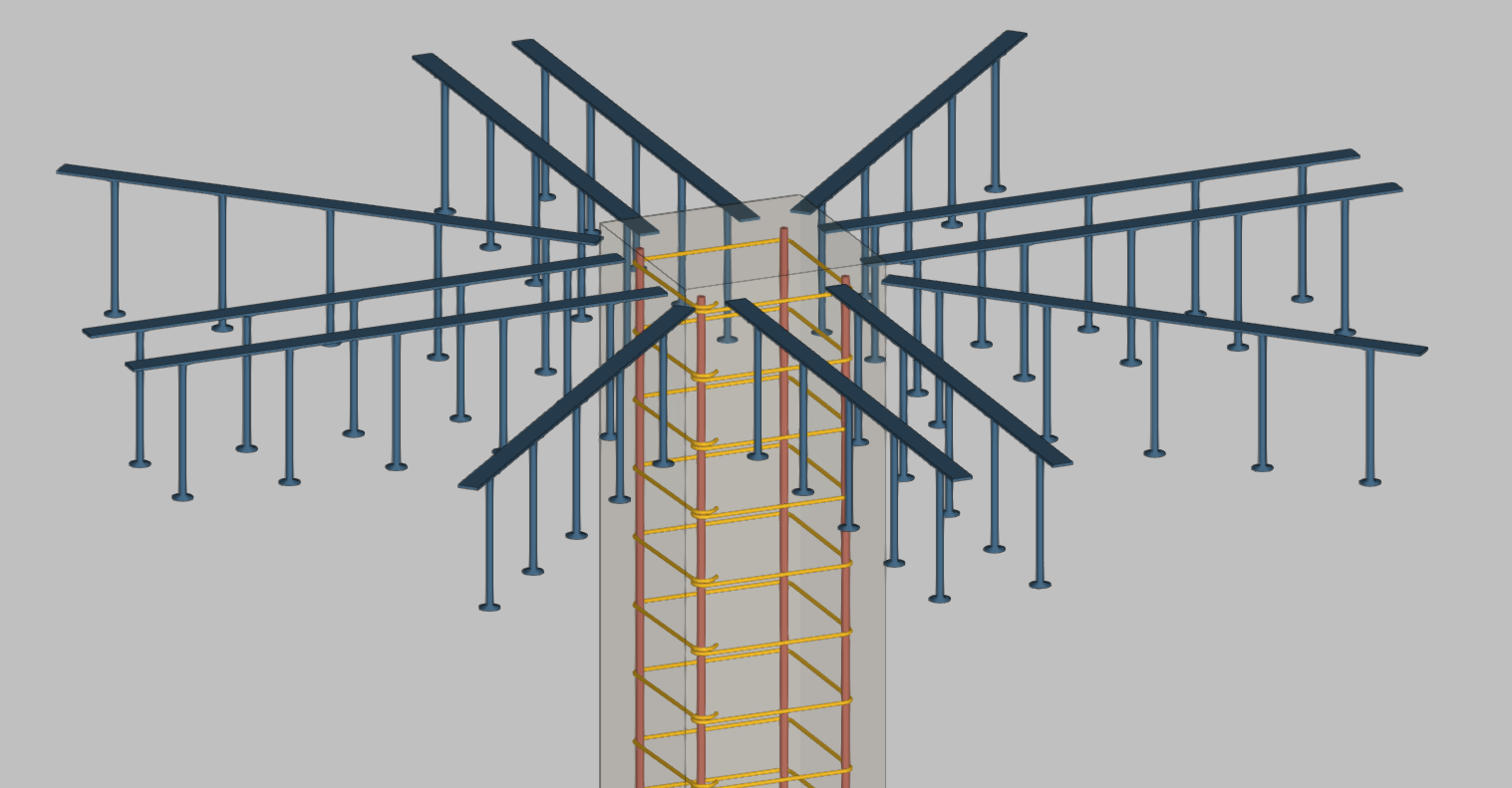
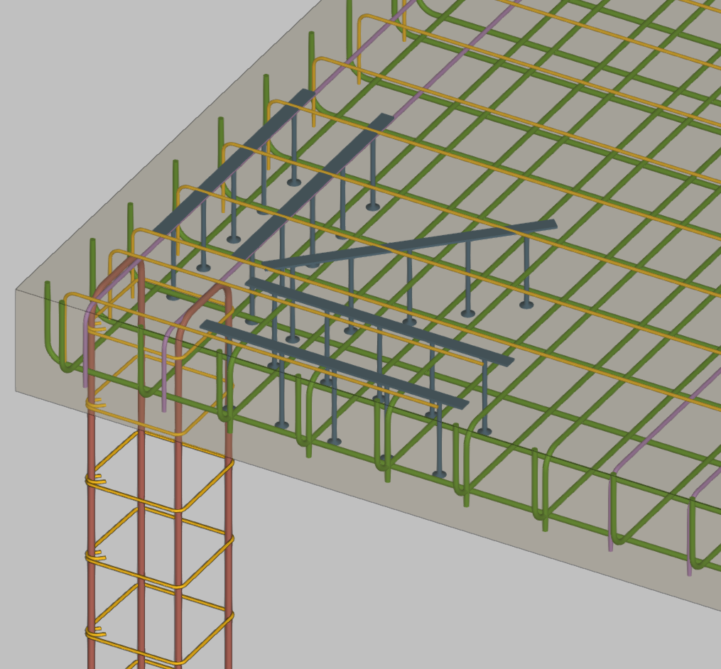
As of version 2024.a, the CYPECAD module "Punching shear verification" allows punching shear reinforcement by means of studs. In the "Results" tab, users can add reinforcement to punching shear by means of studs (Flat/Waffle slabs > Punching shear > Add reinforcement > Studs) and also generate them (Flat/Waffle slabs > Punching shear > Generate reinforcement > Studs).
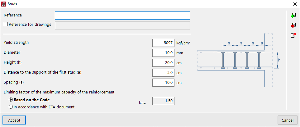
The program carries out the punching shear verification of the slab taking into account the reinforcement entered and the criteria of the selected concrete code.
The codes that have been implemented in this version are the following:
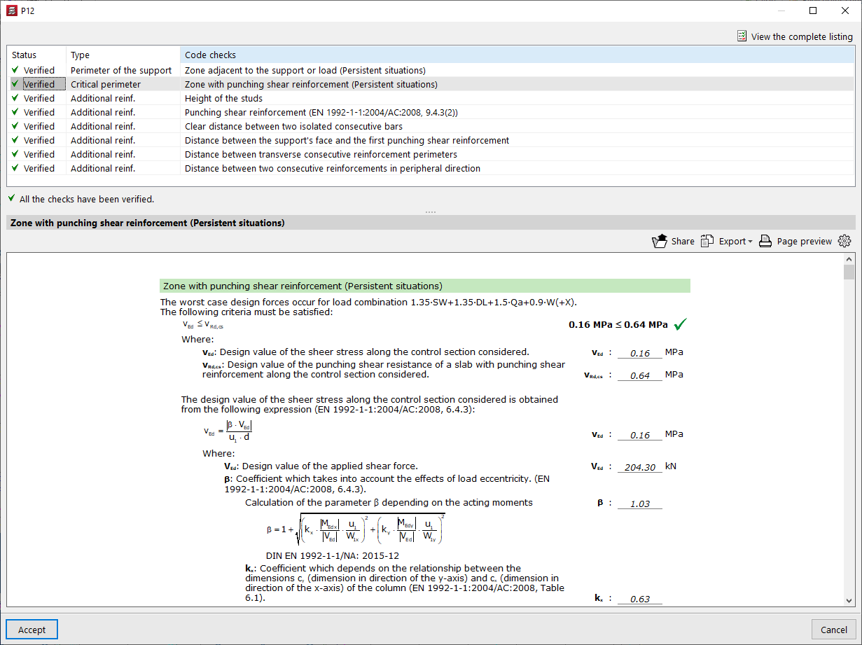
A new "Punching shear" report has been implemented, replacing the "Punching shear checks" report.
In this new report, users can check the data of the elements used as punching shear reinforcement (45-degree reinforcement, beam type reinforcement, and punching shear studs) and their quantities, in addition to the checks.
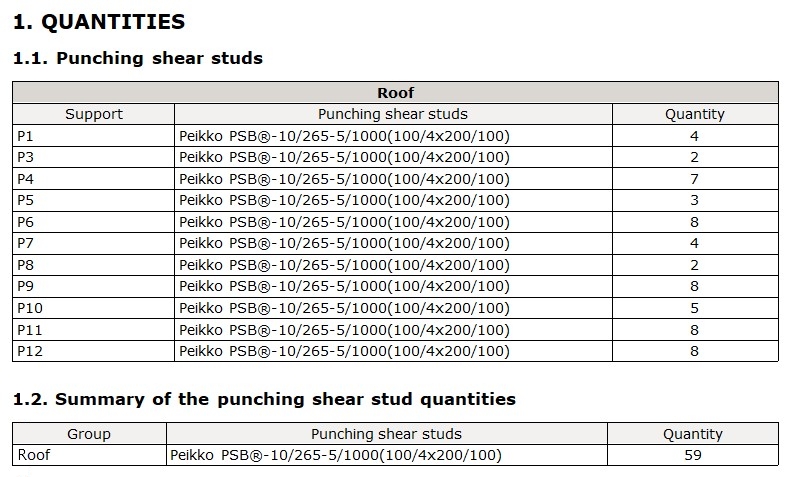
The "Punching shear reinforcement" drawing shows the information on the arranged punching shear reinforcement, including studs.
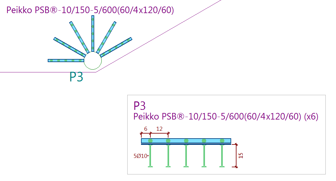
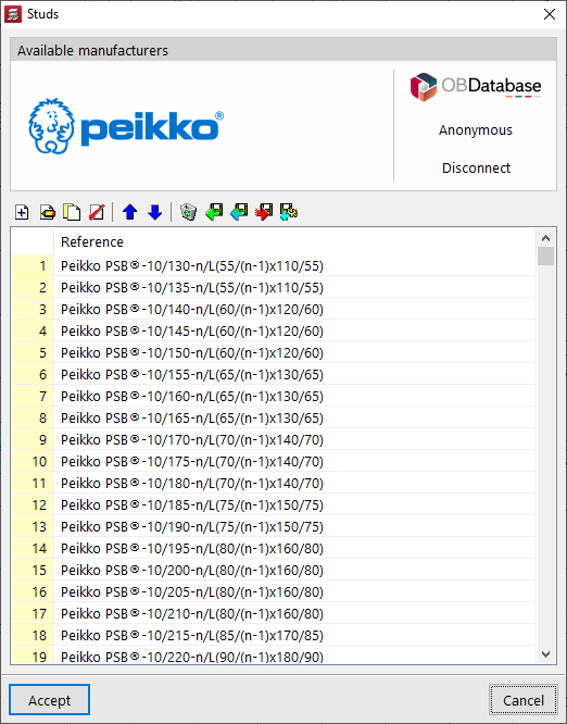
The possibility of using Peikko's PSB® punching shear reinforcement has been incorporated.
The program has all the data provided in the corresponding ETA (European Technical Assessment) document. To use Peikko's reinforcement systems, simply choose one of the available product references from those available.
The range of products available in the program and their analysis data are always kept up to date thanks to the connection to the OBDatabase.
General information
The new CYPECAD ramp module analyses and designs slabs for ramps as isolated elements of the structure. Depending on the geometry, type and layout of the supports and applied gravity loads, the program determines the reactions and applies them as loads on the main structure, resulting in linear loads in the loadcases of dead loads and live loads.
The program resolves ramp cores formed by spans arranged between floors. Each span is made up of one or several elements of one of the types listed below:
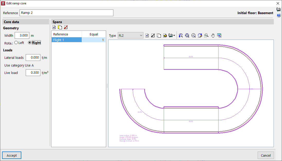
Defining ramp cores
A ramp core is defined by indicating the data common to the core (width, rotation direction, loads) and the particular data of each span.
Ramp spans are fractions of the ramp core that run from one floor to the next. Each span is made up of a succession of straight or curved spans and, optionally, half-turn and quarter-turn intermediate horizontal spans.
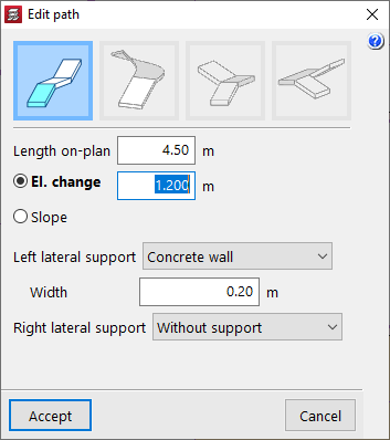
Straight flight
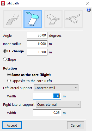
Curved flight
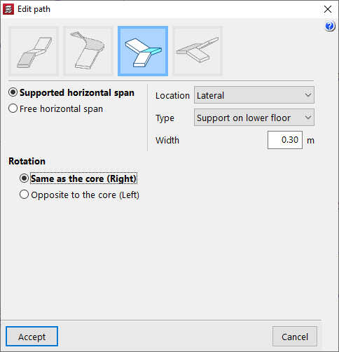
Horizontal span - Quarter turn
Horizontal span - Half turn

Placing in the structure
The start of the first span and a crossing point of the axis of its first run must be specified in order to place the ramp core in the structure. CYPECAD will enter the core with all the spans on the corresponding floors. To help locate these two points, DXF or DWG snaps can be used.
Analysis, results, reports and drawings
The program analyses the ramps separately and using the finite element method, considering the two load cases of dead loads (self-weight and dead loads) and live loads.
CYPECAD displays the reinforcement of each of the spans making up the ramp core on screen. Users can also consult the contour plots of displacements and forces in a 3D view, including the total shear, as well as visualise the deformed shape of each span.
Considering the shear strength criteria of the selected concrete code, the need for shear reinforcement in some areas and the required ratio is determined. If shear reinforcement is required at any point of a ramp, a warning is displayed. The ratio can be found in the "Forces and displacements - Contour plots - Checks" option.
When the job is analysed, all ramp cores are also analysed and their reactions are applied to the main structure as loads.
Each ramp core can also be analysed individually. To do this, the program only needs to be prompted to display the reinforcement, forces and displacements of the ramps. If the job has not been analysed or if changes have been made since the last analysis, only the selected core will be analysed.
The program provides a warning if changes are made to a ramp core after the job has been analysed, as these changes affect the value of the reactions. In this case, the job must be re-analysed in order to take the new reactions into account.
A report of the ramps with general information about the job and specific information for each core can be obtained, including the results obtained for the forces and reinforcements of each span.
The drawings show all the information required for the ramp reinforcements to be defined: longitudinal and transverse sections, tables of characteristics of each span with their geometric data, loads and materials. The reinforcement quantities tables are also included (by cores, spans and total steel summaries).
Configuring the ramp module (materials, reinforcement tables and analysis options)
The concrete used in the ramp cores is the same as the one selected for the floor slabs. The type of steel used in their reinforcement, on the other hand, can be specified separately. The program has two reinforcement tables (longitudinal and transverse) and a series of analysis options for ramps, which can be configured to suit personal preferences.
In version 2024.a of CYPE Architecture, the "Town houses" example job has been included. This is a residential development consisting of 12 two-storey houses with a private garden. The building also has commercial units, a garden, a swimming pool, a gym and an underground car park for 14 vehicles.

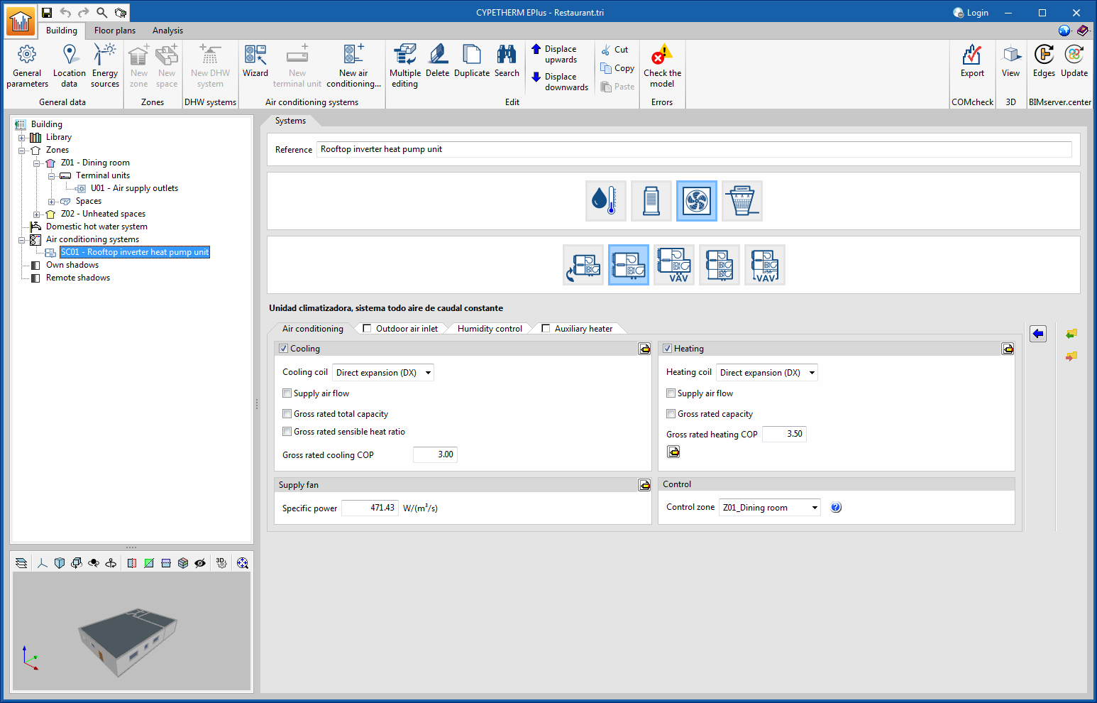
The EnergyPlus calculation model used to simulate the air conditioning unit of the constant air flow system has been changed. Previous versions used a "template" type model available in the calculation engine, which presented configuration and combination restrictions with other systems in the same job. The change of model in version 2024.a eliminates these restrictions. Furthermore, the system definition interface has been divided into tabs to make it clearer.
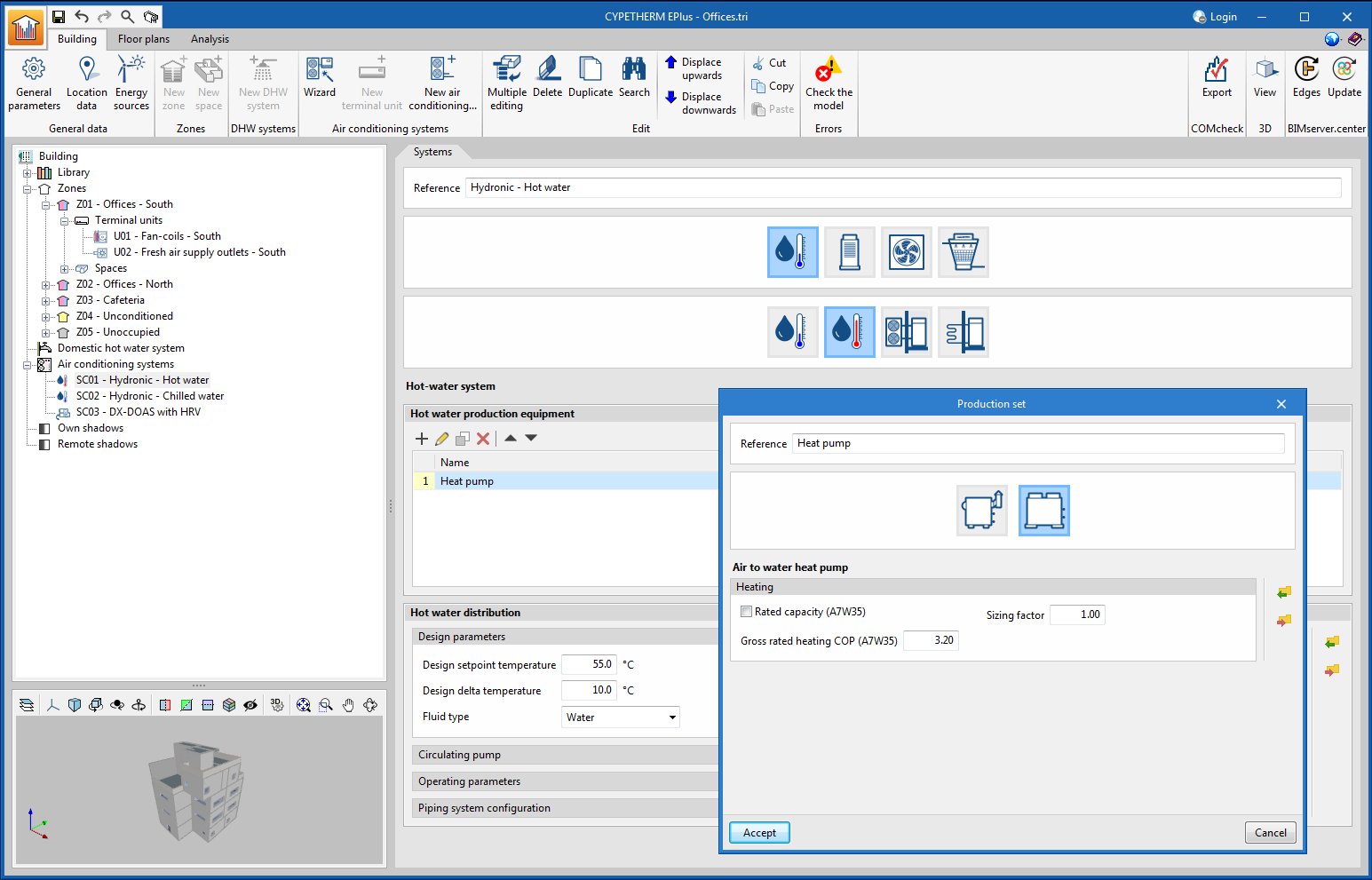
A new production unit has been added to the water heating systems: the air to water heat pump. Several air to water heat pumps can be used in the same circuit in combination with boilers. When selecting a heat pump, the maximum flow temperature of the circuit is limited to 55°C.
In the air to water heat pump window, users must define the rated capacity and gross rated heating COP of the unit for a water temperature of 35ºC and an outside air temperature of 7ºC. These characteristics will vary throughout the simulation according to the operating conditions of the unit, in accordance with the performance curves included in the program.
Water heating systems containing the new air to water heat pump can be connected to the water distribution system terminal units (radiators, radiant floor and fan coils), to the main air conditioner and to the air conditioning unit (AHU) in the constant air flow system.
Norma de Construcción Sismorresistente: Parte general y edificación (NCSE-02)
Implemented in StruBIM Shear Walls.
In addition to the NCSE-02 seismic code, StruBIM Shear Walls version 2024.a has implemented the Spanish structural code "Código Estructural". Please note that in StruBIM Shear Walls the selection of compatible concrete and seismic codes is made together.

"Código Estructural (Real Decreto 470/2021)".
Implemented in StruBIM Shear Walls.
In addition to the Spanish structural code "Código Estructural", StruBIM Shear Walls version 2024.a has implemented the Spanish seismic code NCSE-02. Please note that in StruBIM Shear Walls the selection of compatible concrete and seismic codes is made together.
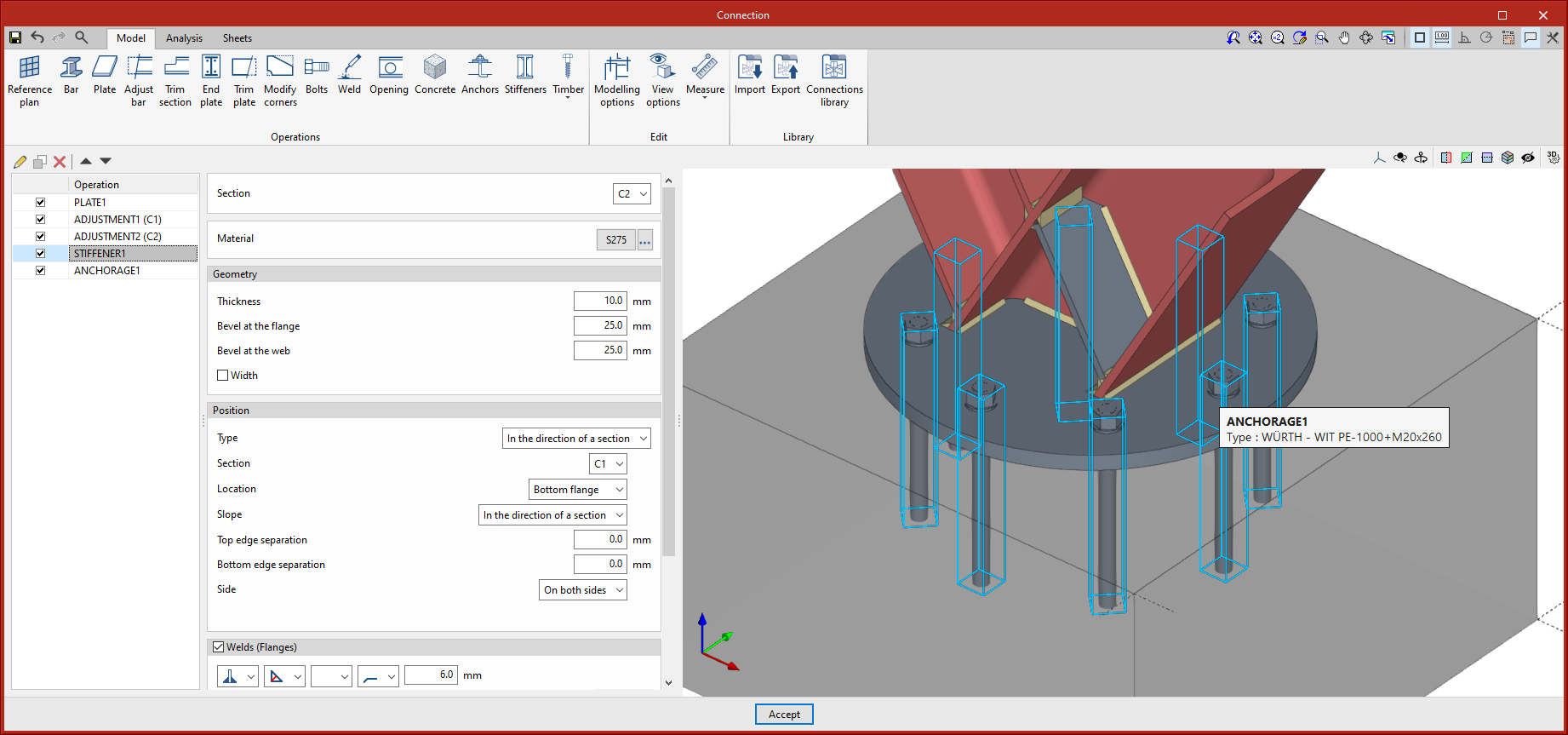
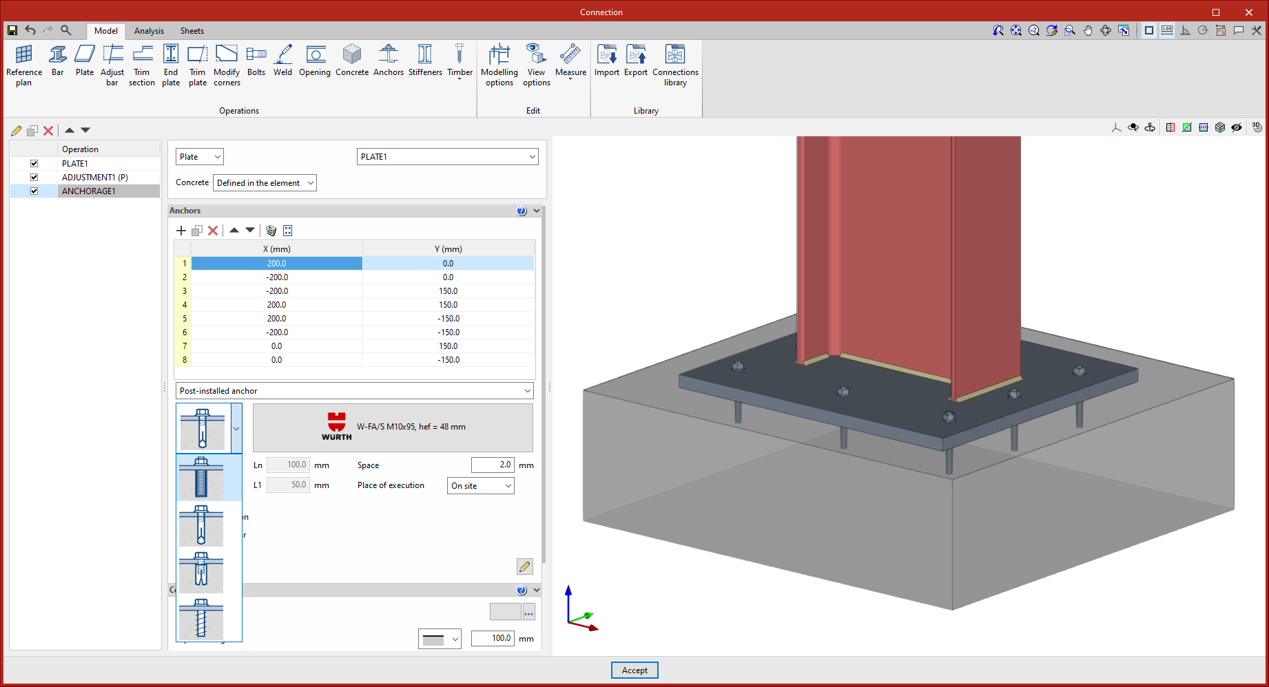
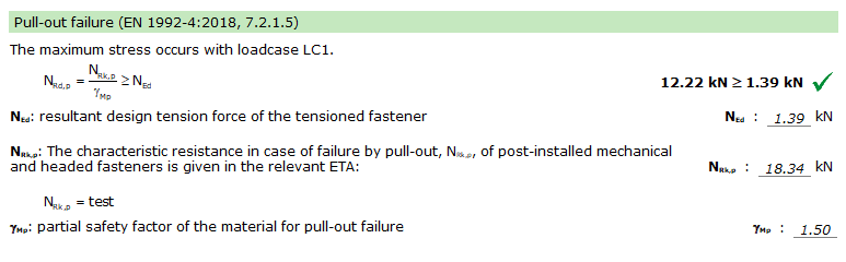
Version 2024.a of CYPE Connect and StruBIM Steel now includes the ability to use post-installed chemical anchors and mechanical anchors from the WÜRTH brand catalogue as concrete fixings in baseplates. The checking of these elements is carried out in accordance with the criteria in the EN 1992-4:2018 standard, based on the data provided in the corresponding ETA (European Technical Assessment) for each fixing.
The Würth brand post-installed anchors included in version 2024.a are the following:
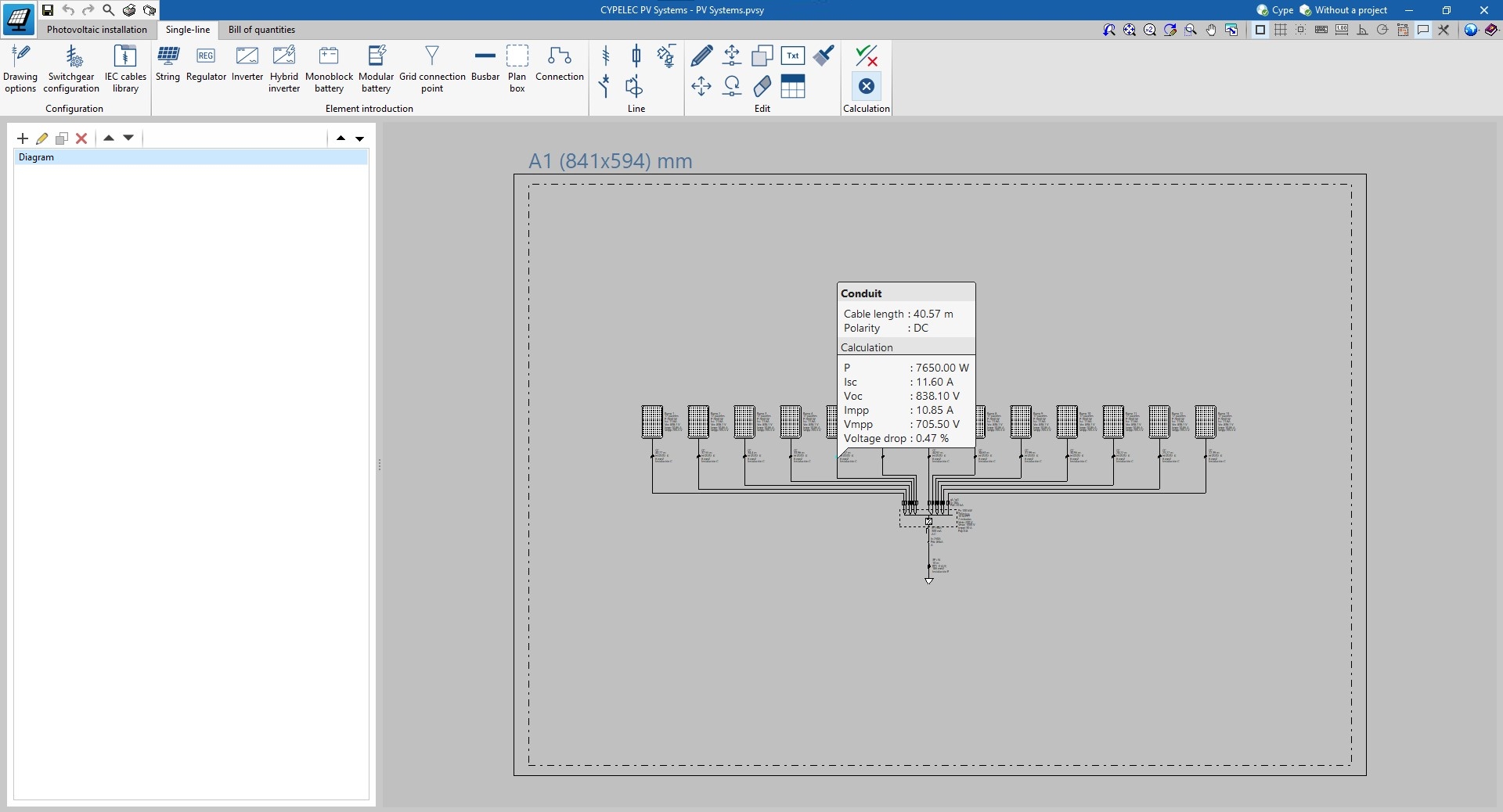
As a result of the removal of the wiring modelling restriction in the "Photovoltaic installation" tab, the wiring parameters and the wiring analyses and checks are carried out in the "Single-line" tab.
In version 2024.a, the consumption can be found in the "Design conditions" window. As a result, this data is shared between the predesigner and the model, allowing users to analyse and check off-grid systems on the basis of this consumption in the model.
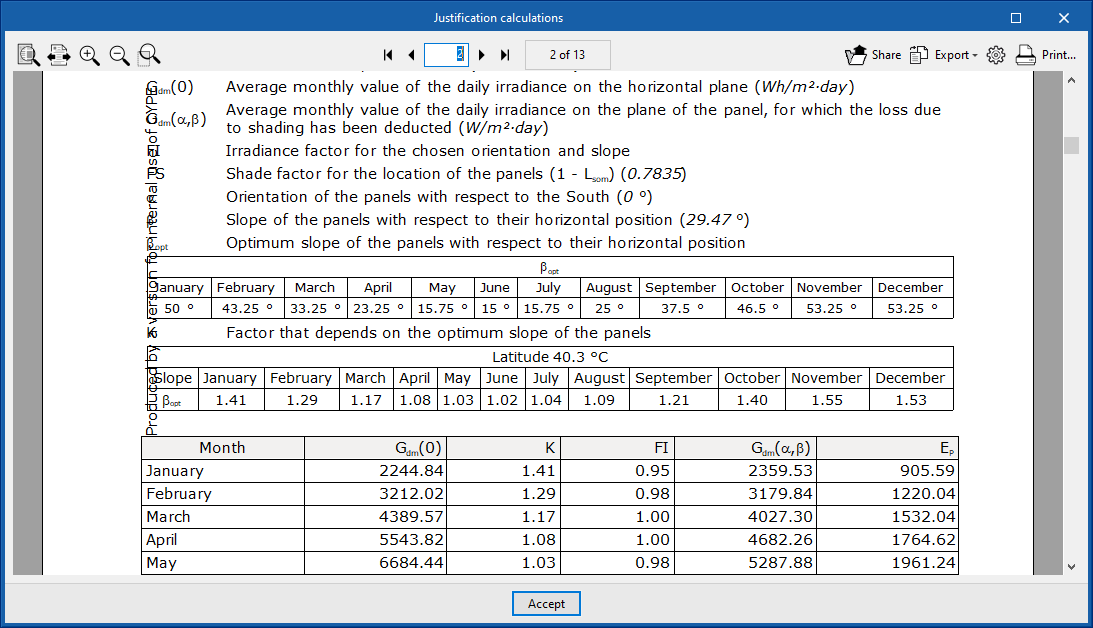
The analysis of energy produced by the photovoltaic system no longer considers the optimum tilt for each period (winter and summer). When calculating the tilt factor, the new version now considers the optimum tilt per month depending on the project's latitude. Therefore, the analysis of the energy produced per panel is more accurate.
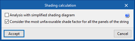
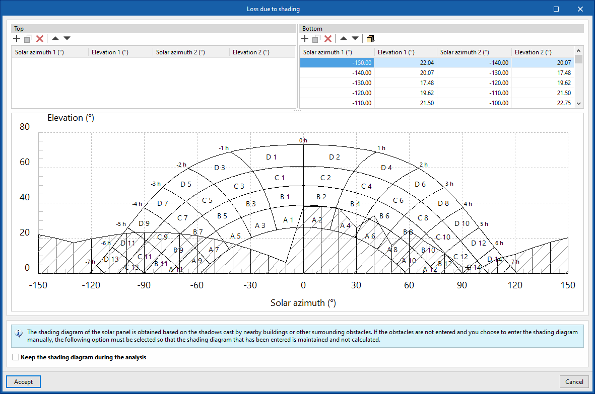
The introduction of the "String" concept in the program means that when it comes to calculating and generating the shading diagram of the solar panels, users can select whether they want to do this per string or per panel. For this purpose, there are two options in the shading calculation:
When creating the shading diagram of the solar panels, in addition to the architectural elements that cast shadows on the panels, the solar panel is added to this function as an own element of shading generation. This way, the generation of shading between the solar panels can be taken into account.
In version 2024.a, for the modelling carried out in the "Photovoltaic installation" tab, entering the wiring is optional. Now, when entering each element, the output element is specified so that the subsequent analysis of electrical parameters can be carried out.
On the other hand, the "Row of panels" feature has been added to make it easier to enter panels quickly. This tool allows a row of panels to be entered with a general configuration for all of them, by simply defining two points in the space.
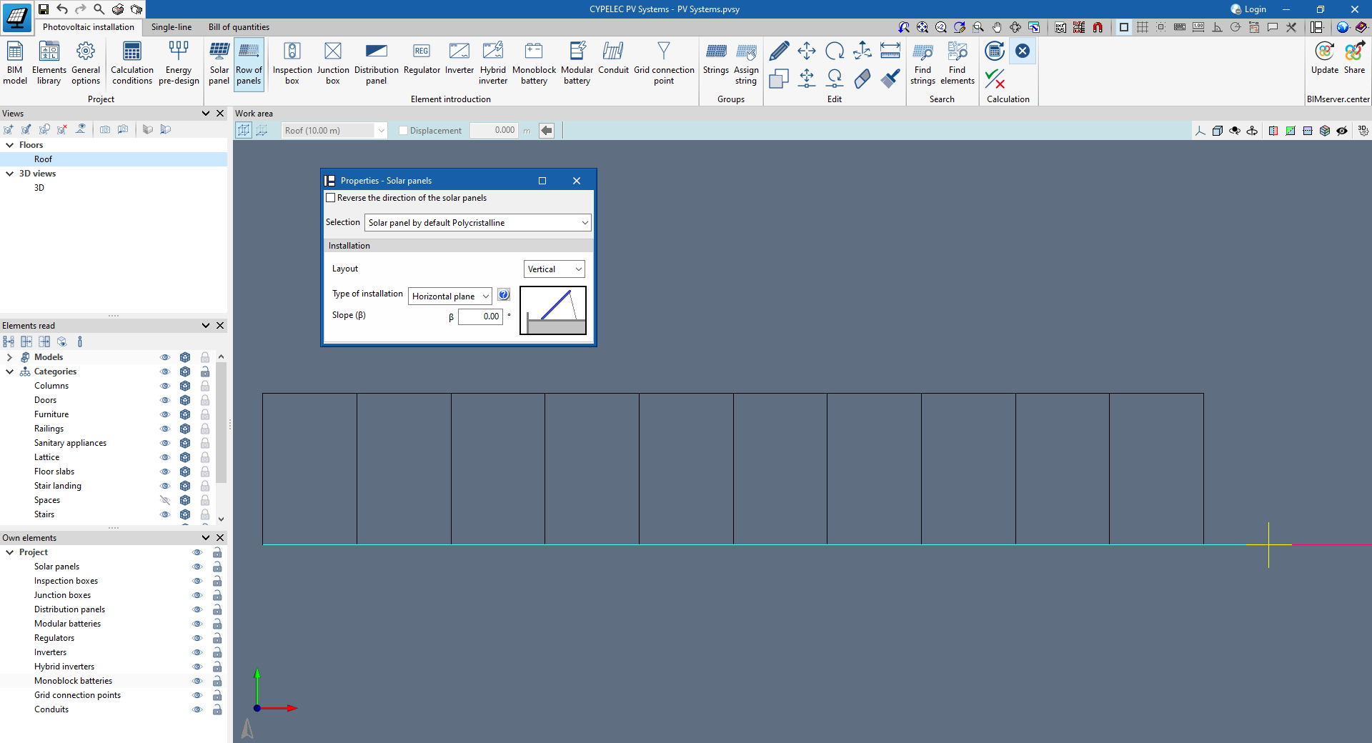
The selection of the panel layout (either horizontal or vertical) is added to the existing features of a solar panel when it is entered.
This way, the same type of solar panel from the element library is applied for the analyses and checks, regardless of the layout chosen.
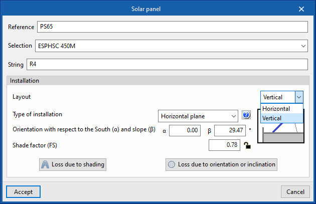
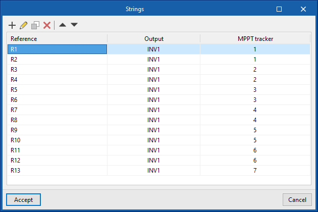
The "string" concept has been added to the program. Using the "Strings" tool, strings can be created in the job in order to be subsequently assigned to the panels found in the model.
Once this assignment has been made, the program checks and analyses the string parameters for the subsequent analysis of the entire system.
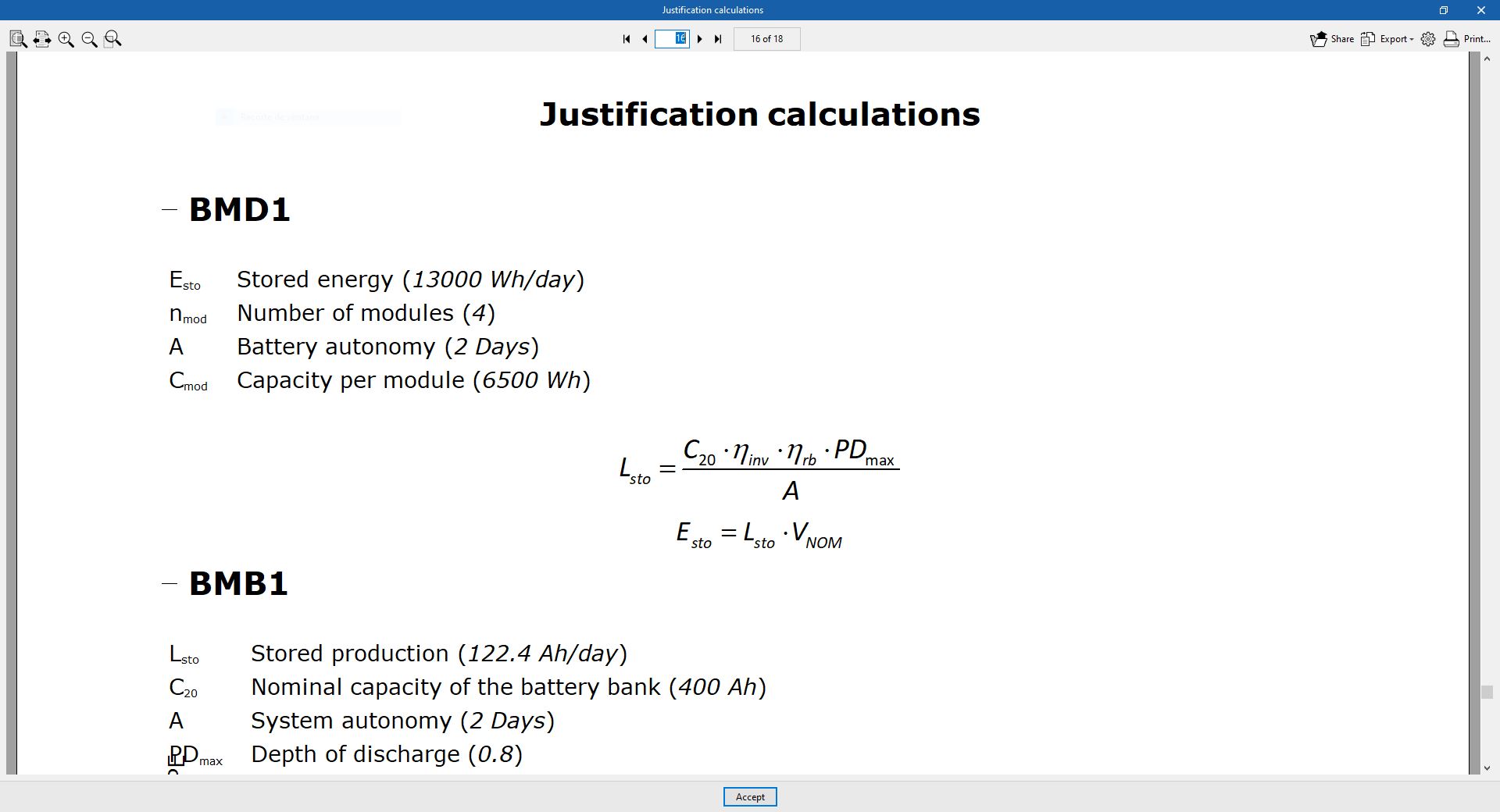
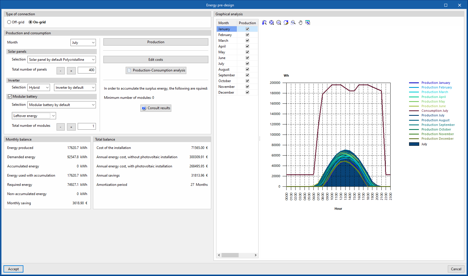
As a result of the added "Hybrid inverters" and "Modular batteries" elements, the types of systems supported by the predesigner have been increased. The types of systems analysed by the predesigner are now as follows:
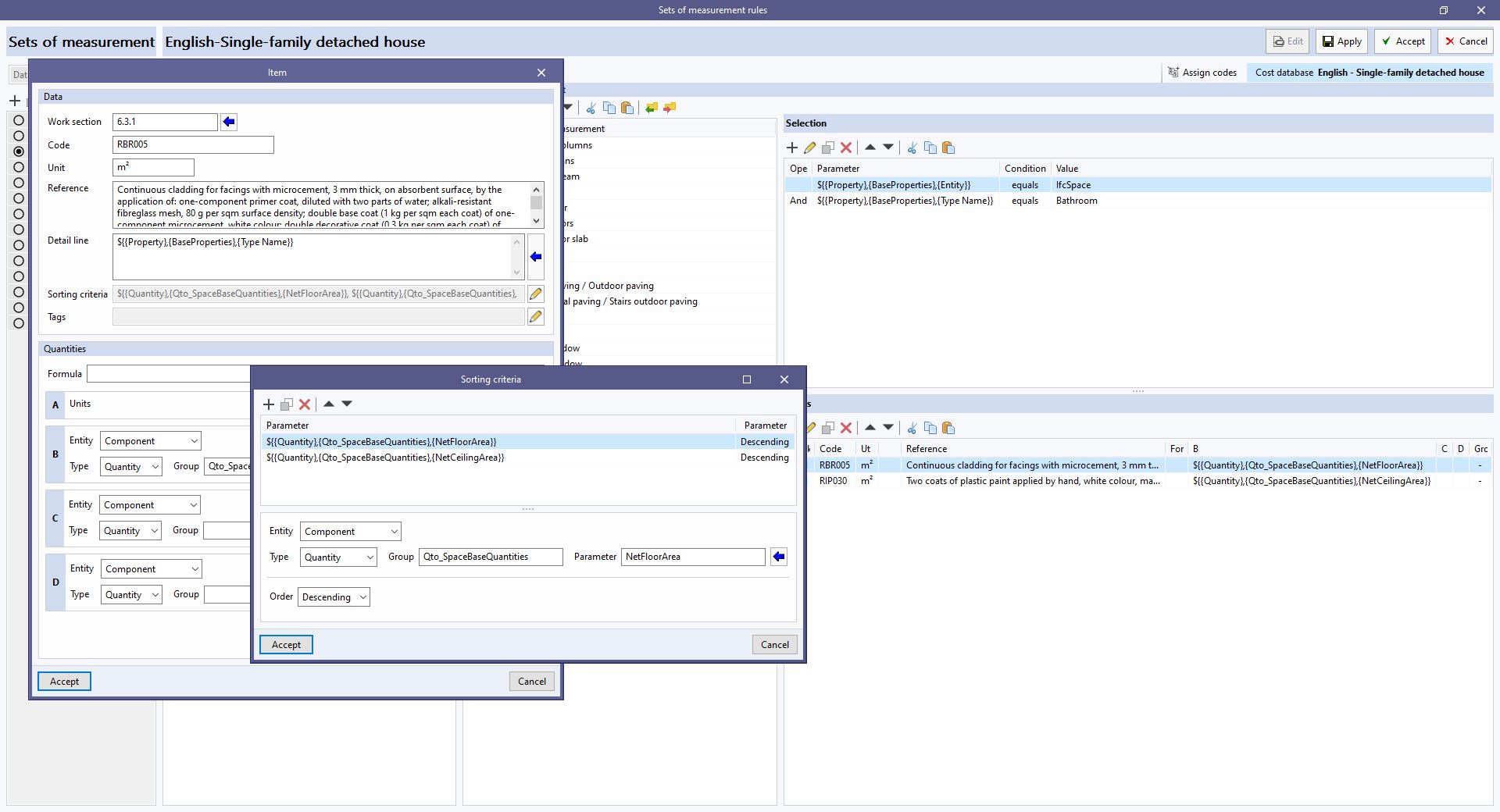
The "Sorting criteria" field has been added to the editing window of an "Item", in a rule of measurement. This way, users can now indicate the order in which the quantity detail lines should be inserted in the item after applying the set of measurement rules to the model.
When editing the "Sorting criteria" field, a list is displayed where users can select properties and quantities of the BIM model components, and also indicate whether they want to sort the value in "Ascending" or "Descending" order. Different sorting criteria can be entered so that when the criterion parameter coincides with several quantity detail lines, the next one in the list will be applied. If no criteria have been specified or if all the criteria match, the same criteria that have been used in previous versions shall be used. This compares the attributes of the quantity detail lines in the following order:
As of version 2024.a, CYPEPLUMBING Sanitary Systems allows a cost database of resources based on the CYPE's construction cost databases "Generadores de precios" to be generated. For this purpose, the "Price Generator - CYPEPLUMBING Sanitary Systems ([version] - [date])" option has been added to the window for creating a cost database, in the "Bill of quantities" tab of the application. When selected, a new button will appear to define the "Site data" of the job, this location will be used to complete the information associated with the resources.
Once the window has been accepted, users can visualise the concepts that have been generated, grouped in a work section structure. Each concept corresponds to a different material and contains a breakdown which includes the labour and auxiliary materials necessary for its installation as well as the material itself. It is important to highlight that, apart from the price, these elements contain information regarding their physical properties, environmental data and waste.

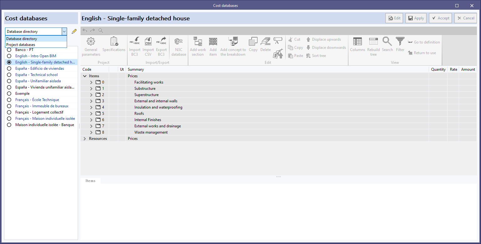
As of version 2024.a, users can manage the "Cost databases" and "Mapping files" databases (in applications with a "bill of quantities" tab), and the "Sets of measurement rules" databases (for Open BIM Quantities) in two different locations, which can be toggled via a drop-down menu:
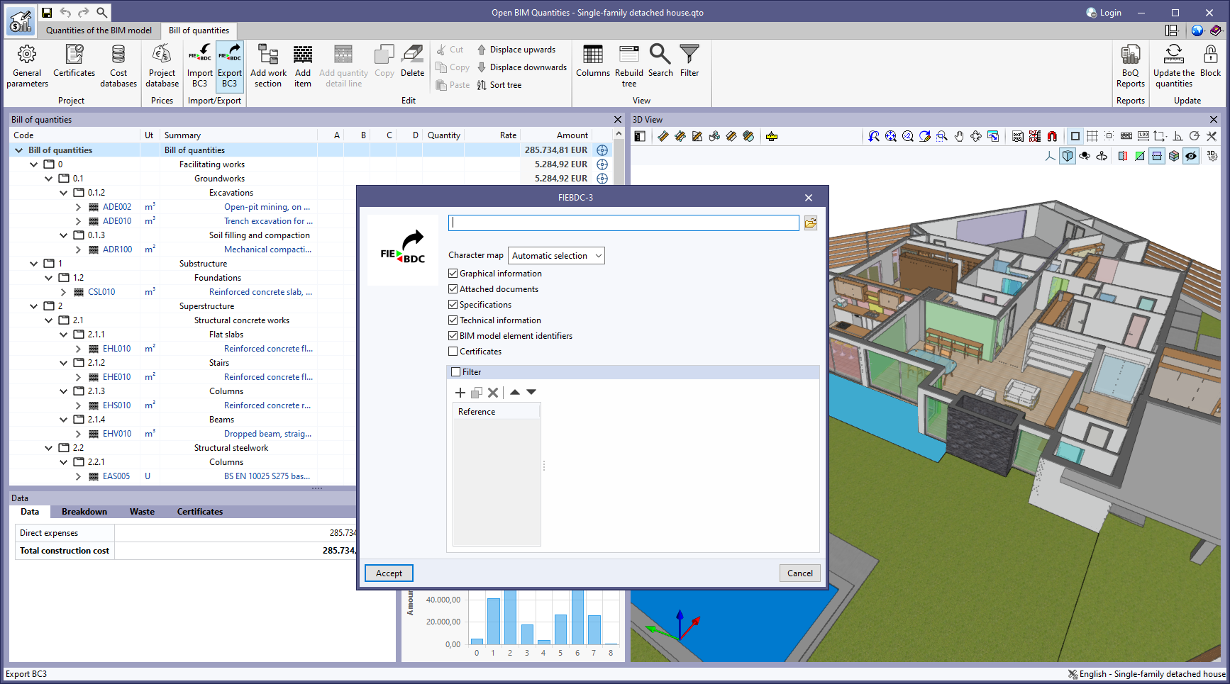
The "BIM model element identifiers" option has been added to the bill of quantities export panel to FIEBDC-3 format (.bc3). When activated, the IDs of the elements in the BIM model will be added to the comments of the quantity detail lines, as indicated in the code from version FIEBDC-3/2016. In previous versions, these fields were always added to the file, but to ensure compatibility with other applications that are not able to work with them, the export of these fields can now be controlled.
This option is activated by default. Furthermore, the FIEBDC-3 files included by the "Bill of quantities" tab in the contributions for the BIMserver.center platform always contain the identifiers of the BIM model elements.
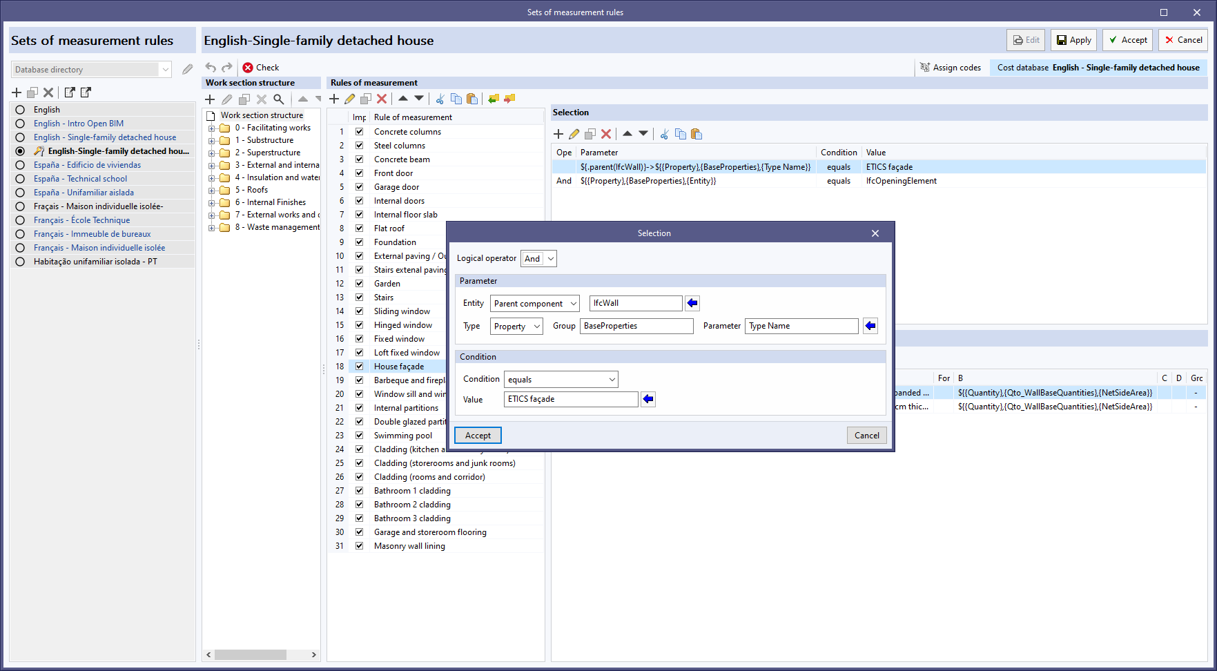
As of version 2023.g, Open BIM Quantities can read and display composite elements from the IFC model. Now, in version 2024.a, this relationship between components can be used for generating the bill of quantities via the rules of measurement. For this purpose, the "Spatial structure element" option in the drop-down menu associated with the "Entity" field has been replaced by the "Parent component" option. This allows users to access the parent entity of the selected element without the need for it to be a spatial structure element ("IfcSite", "IfcBuilding", "IfcBuildingStorey" or "IfcSpace"), as was the case in previous versions. To make it easier to select the parent component, a button has been added that displays a list of all the IFC entities available in the model.
An example of using this new feature is the subtraction of the area of the openings ("IfcOpeningElement") contained in a wall ("IfcWall") or slab ("IfcSlab") from the gross area of the building element ("GrossSideArea") when the net area ("NetSideArea") is not available. The properties of the individual components of an element defined by parts ("IfcBuildingElementPart") can also be accessed.
In version 2024.a of StruBIM Steel and CYPE Connect, the management of I-sections with haunches has been implemented.
Export / Import:
The parametric information of the haunches has been included in the CYPE 3D and CYPECAD export to IFC format.
StruBIM Steel and CYPE Connect import the bars contained in these IFC files and, in the case of sections with haunches, they are imported with the aforementioned parametric information.

Defining sections with haunches:
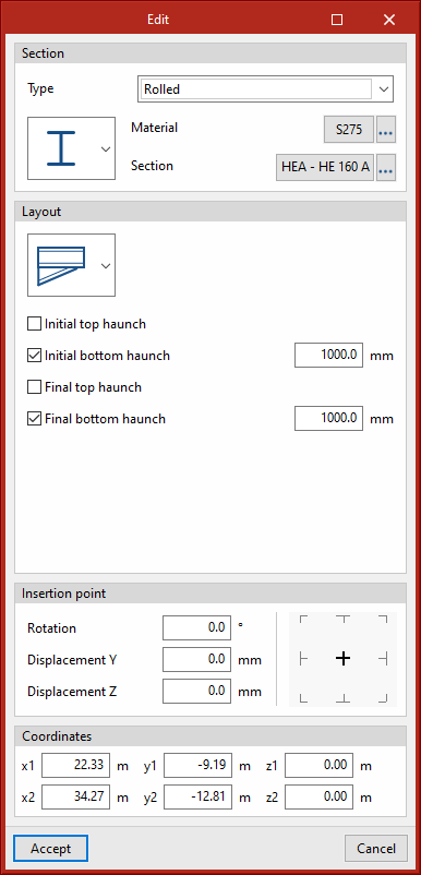
In version 2024.a of CYPE Connect and StruBIM Steel, the implemented haunches are the same section as the selected rolled section and users can define the length of the haunch.
In CYPE Connect, the "Layout" section has been implemented for I sections, where users can choose between the "Simple section" or "Simple with haunches" options.
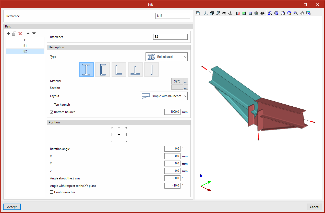
In StruBIM Steel, I sections also allow users to define a simple section with haunches using the options available in the "Layout" section of the "Edit" dialogue box.
Connections
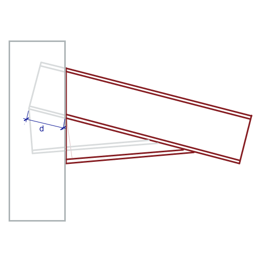
In the connection editor, when using the "Adjust bar" or "End plate" operations, the haunch will be moved in the direction of the base section in order to maintain the highest possible depth at the start of the bar. The edge of the haunch (measured perpendicularly to its flange and to the start of the bar) is equal to the edge of the base section minus the thickness of one flange.
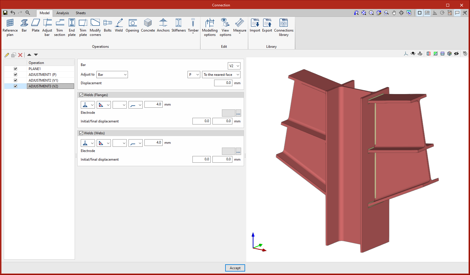
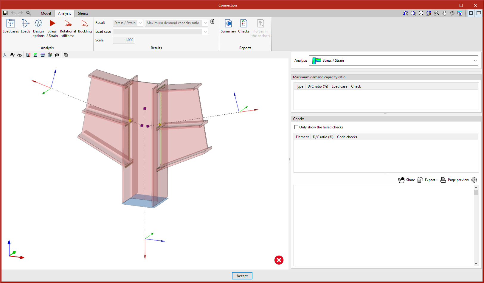
As for the analysis, the haunches are considered to be joined to the base section without the need to define the weld joining them and the forces in sections with haunches are referred to the centre of gravity of the composite section.
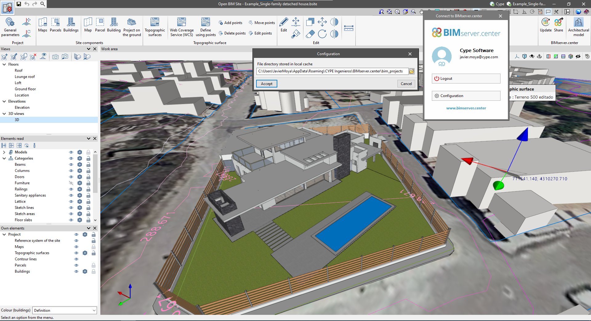
The mode of communication between Open BIM applications and the BIMserver.center collaborative work platform has changed. In previous versions, the applications used the "BIMserver.center Sync" tool to upload and download the files of the contributions associated with the project from the platform. This tool was downloaded from the BIMserver.center platform or installed together with the installation of the platform applications if users so desired.
From version 2024.a onwards, applications are now able to work directly with BIMserver.center without an intermediary. That is, without the need for the "BIMserver.center Sync" tool.
This modification will improve the performance and efficiency of Open BIM applications significantly. By removing this dependency, the applications have more autonomy and the waiting times for communication between BIMserver.center Sync and the program have been considerably reduced. The process of downloading contributions has also been optimised, as users no longer need to obtain the entire content of a project from BIMserver.center in order to work, but only the contributions to be read.
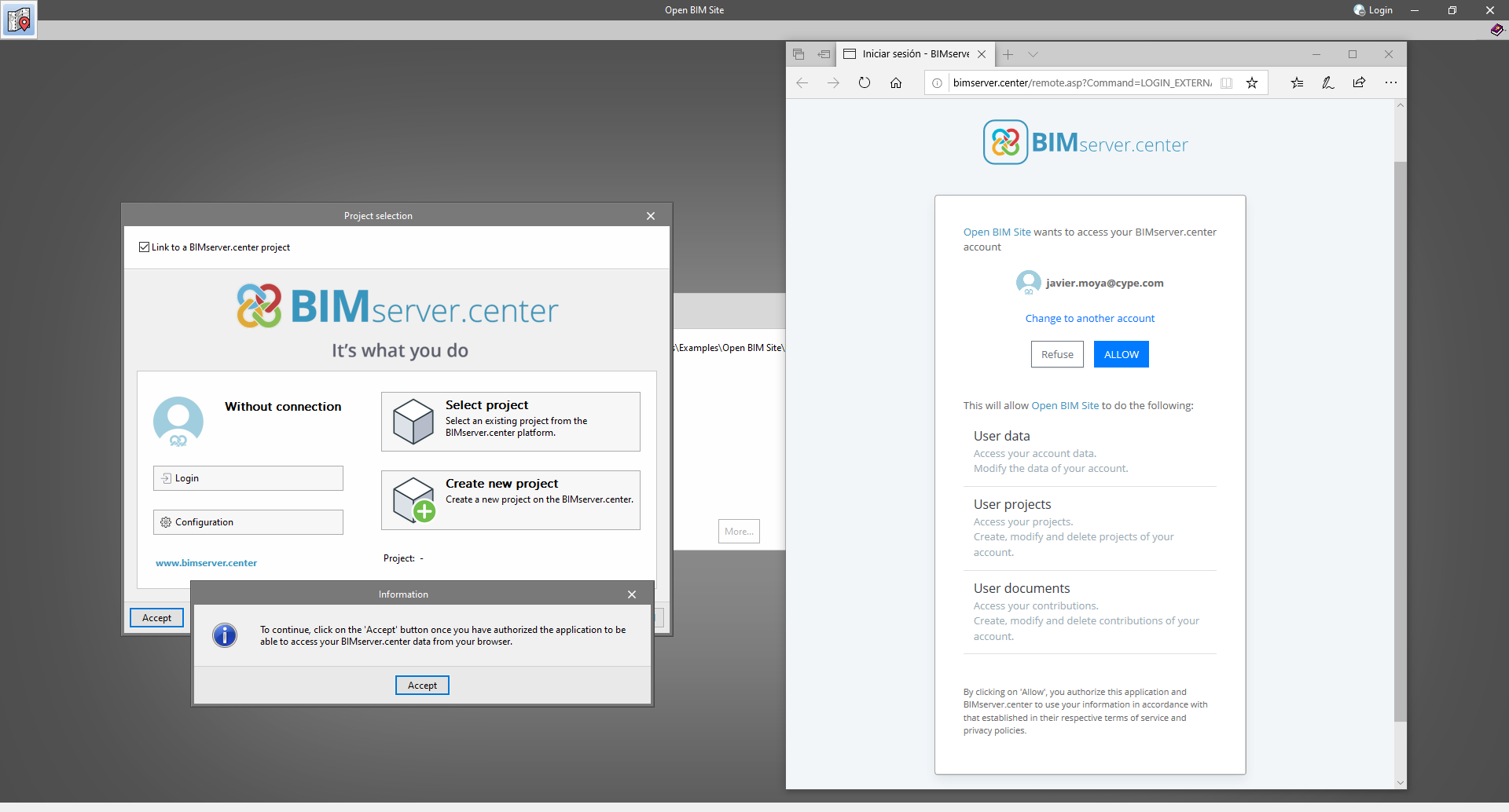
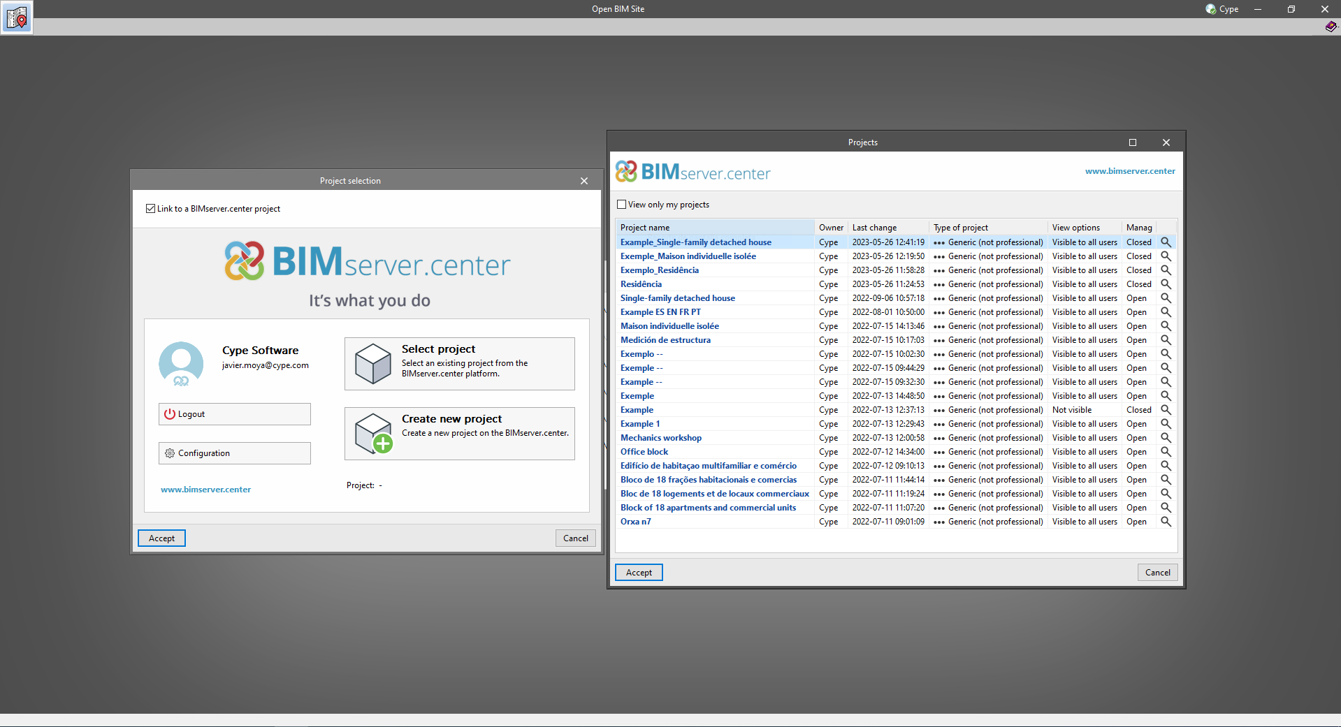
The way of authenticating a BIMserver.center user in the applications has also been modified. Now, this process is carried out within the BIMserver.center web platform. To do this, the application with which the user is working will run the user's default browser when the "Login" button is pressed. When the credentials are entered, or after opening the browser if the user is already connected to the platform, an authorisation page will be displayed. This page details the resources the application is requesting access to and two buttons for granting or denying this access.
The authorisation must be carried out for each application. Once access has been granted, it is saved for the next time the program is run and there is no need to perform this process again for that application.
As well as performance improvements, changes have been made to the user interface of the Open BIM applications regarding the connection to BIMserver.center.
To work in BIMserver.center with versions of Open BIM applications prior to 2024.a, users must continue to use the BIMserver.center Sync tool. This is still available for download from the platform and was included in the installation packages of the CYPE Open BIM applications prior to 2024.a.
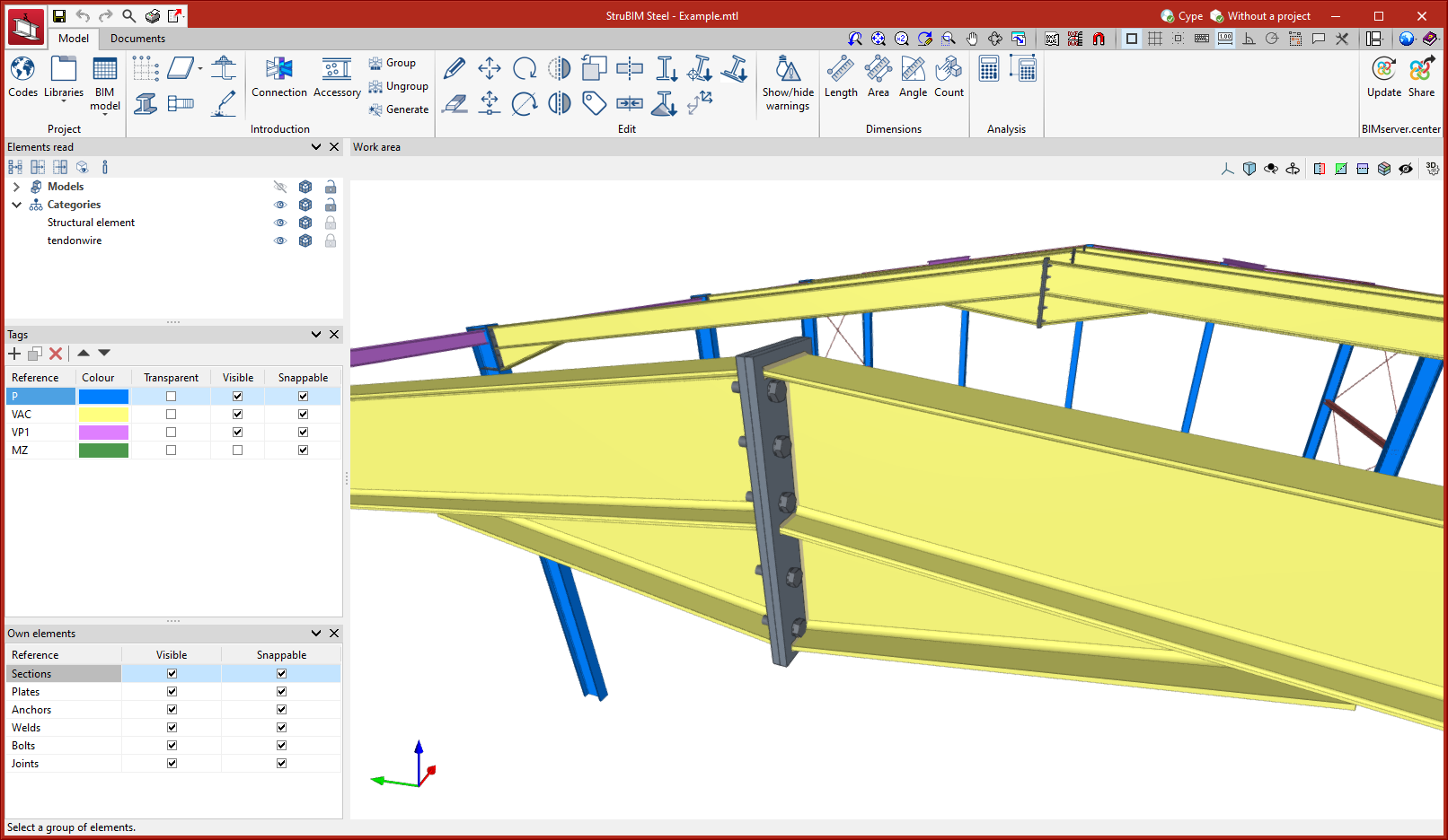
Up until version 2024.a, the work environment consisted of a tree of chapters containing the different detailing of the structural elements of the project. As of version 2024.a, this work environment is located in the "Elements" tab.
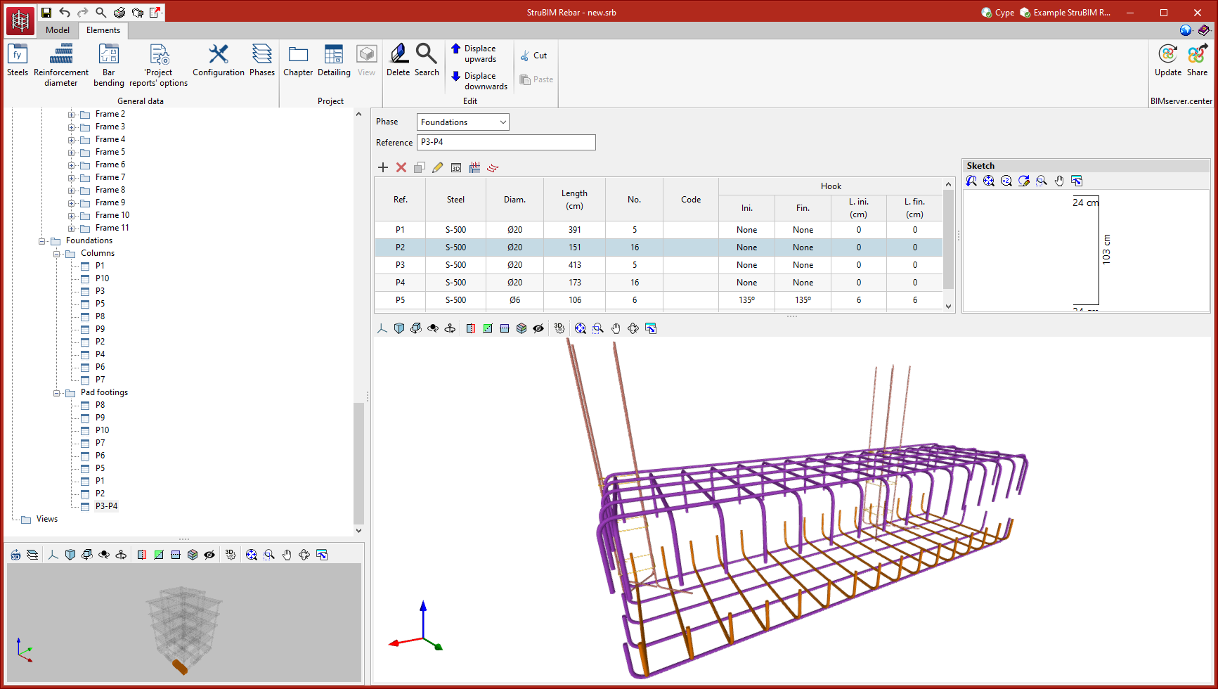
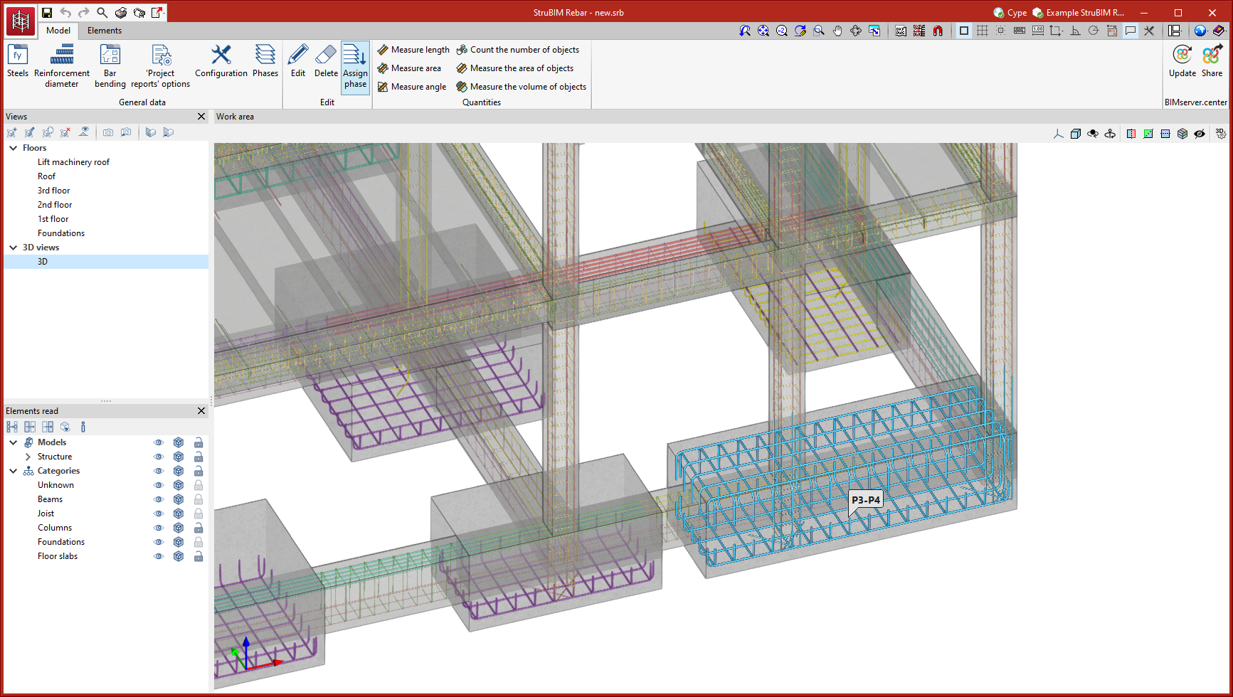
Version 2024.a includes a new tab in the work environment. This new tab, "Model", contains the work area in the central part and a sidebar where the views and the elements read from the BIM model can be managed.
The following tools can be found in the "Model" tab of the "Edit" menu:
