MS 1553:2002, AMD. 1:2013. Code of practice on wind loading for building structure. AMENDMENT 1
Implemented in CYPECAD.


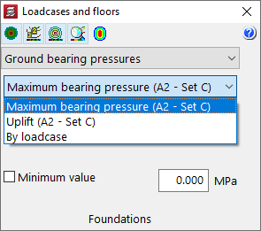
When a Eurocode has been selected in "Ground bearing pressures", it is now possible to display the values corresponding to each of the sets of coefficients according to the project approach used. The sets displayed depend on the project situations selected in the "Foundation soil" option.
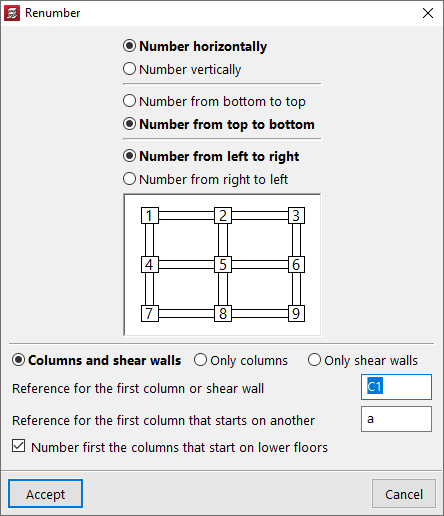
With this new option, the numbering of columns and shear walls can be changed according to their position.
Users will not need to carry out another analysis in order for the new numbering to be shown on drawings and reports.
In version 2023.c, the limit drift between floors due to seismic action was implemented in CYPECAD by means of user-entered values.
Now, in version 2023.e, the limit drift between floors due to seismic action can be selected for several codes.
An automatic selection can be made according to one of the codes in which the drifts have been implemented, or the values can be entered manually.
An indication is given in the final report of the analysis if any of the elements do not comply with any of the selected limits.
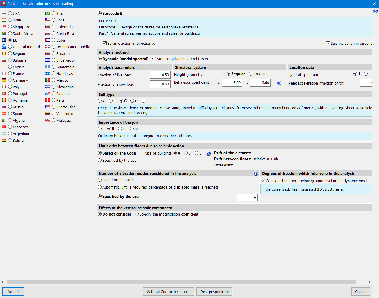
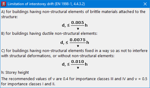
The codes in which the limit drift between floors due to seismic action have been added in version 2023.e are:
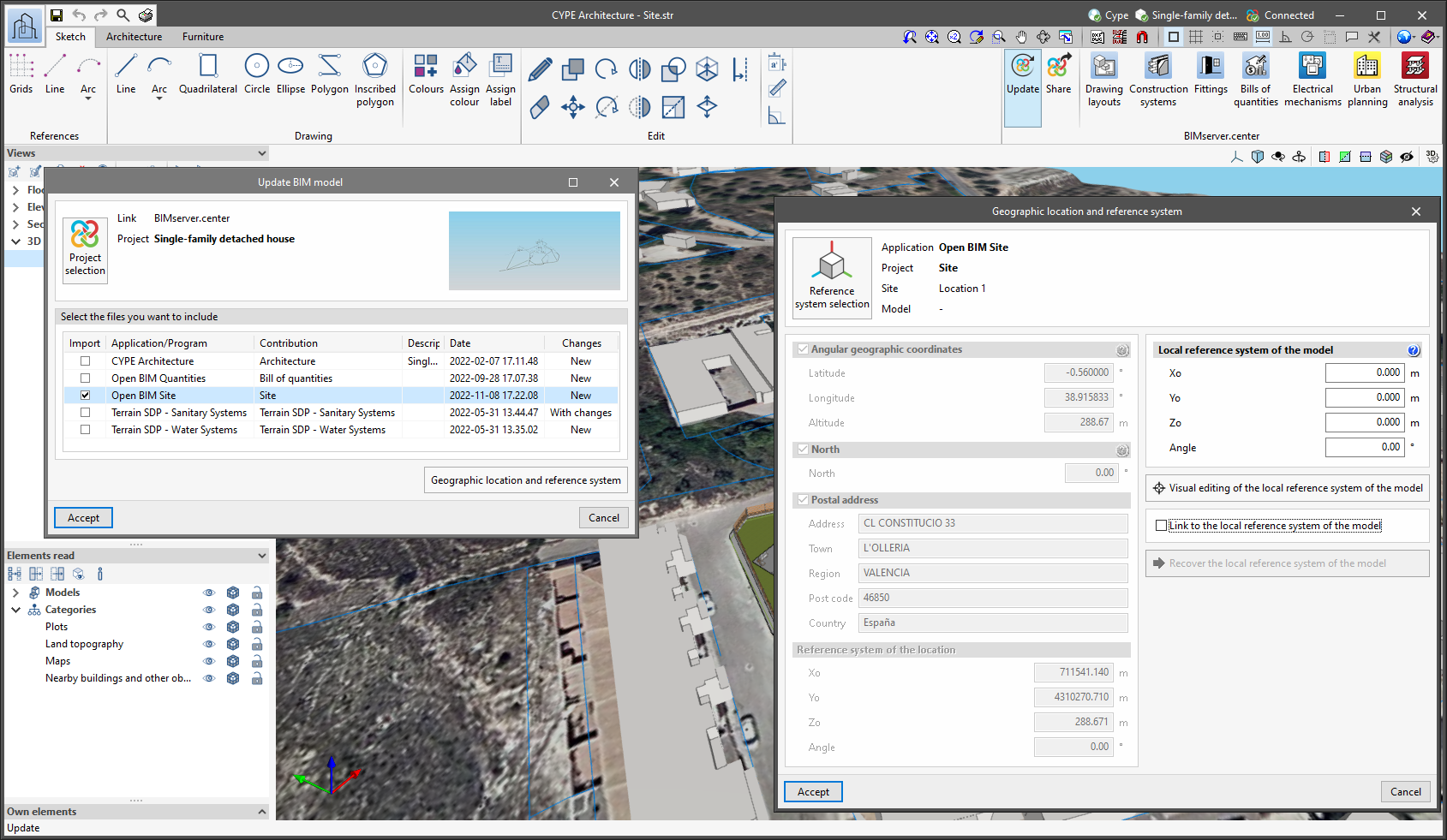
Since version 2022.a, the applications integrated within the Open BIM workflow via the BIMserver.center platform include a tool for managing project reference systems. This option is available from the configuration window that appears when linking or updating a BIMserver.center project via the "Geographic location and reference system" option. As of version 2023.d, the applications now allow users to run a graphical environment where they can visually define a reference system for their model. To do this, the "Geographic location and reference system" window now contains the "Visual editing of the local reference system of the model" option.
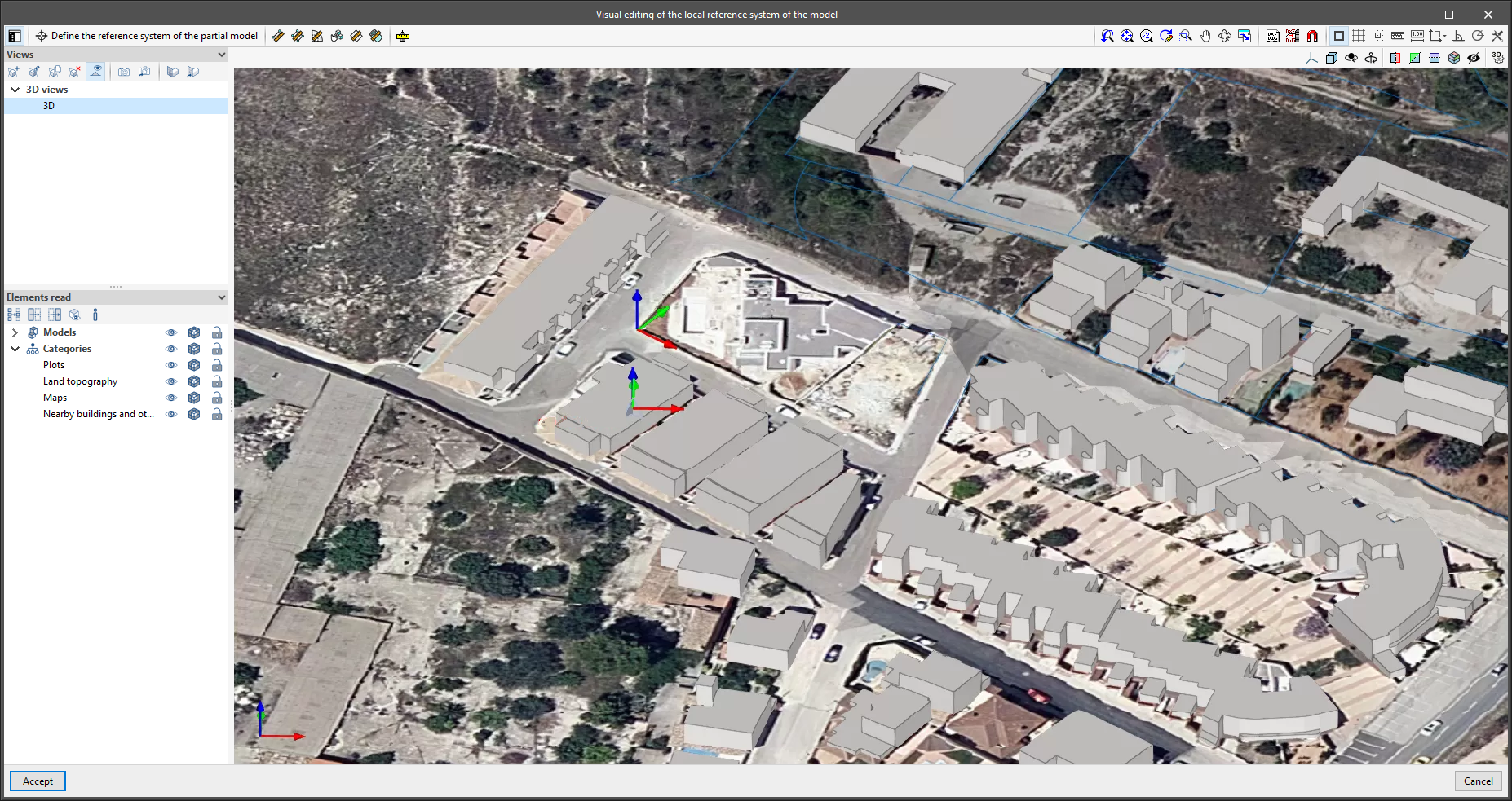
From the "Visual editing of the local reference system of the model" window, the origin and orientation of the reference system of the model can be indicated in the workspace with the "Define the reference system of the partial model" tool. Both the axes of the reference system of the model, which we have just entered and the axes of the reference system of the site can be viewed in the workspace. The latter appears with a "Site" tag.
To make it easier to define the reference system, the 3D models corresponding to the BIMserver.center project contributions selected during the linking process are displayed. The management of the visibility and object snaps of these models is carried out from the "Elements read" menu in the left sidebar of the window. The "Views" menu can also be found in the same options bar, from which different types of 2D and 3D views of the model can be generated. These tools can already be found in several CYPE applications. For more information on how they work, please refer to the User’s Manual for the 3D work environment tools available in CYPE applications.
Apart from 3D models, 2D drawings or plans can also be imported from CAD files (".dxf", ".dwg", ".dwf") or images (".jpeg", ".jpg", ".bmp", ".png", ".wmf", ".emf", ".pcx"). These files and object snaps are managed through the "DXF-DWG Template" and "Template object snaps" options accordingly.
Once the editing is complete, the coordinates and orientation of the reference system of the model with respect to the reference system of the site are moved to the corresponding fields in the "Geographic location and reference system" window.
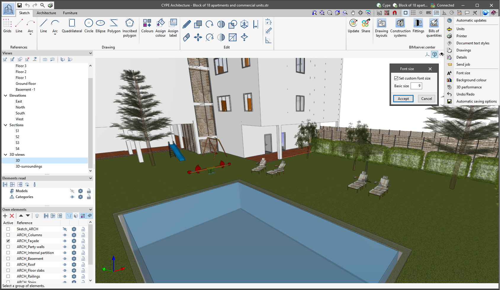
The "Font size" option has been added to the general configuration menu of the applications. This tool allows users to increase or decrease the basic size of the font used in the user interface of the programs. Thanks to this implementation, the accessibility of the applications has been improved while also ensuring the correct visibility of the content on devices with different screen resolutions.
To enter a "Basic size" the "Set custom font size" option must be checked. The size users can enter is the application's basic font size. Any other font sizes that may exist in the program's interface will be automatically modified proportionally according to the change in the basic size.
It is important to note that, as this is a common parameter, its modification will affect all installed CYPE tools.