CYPE Mentor

Update history​​

CYPECAD

Version 2022.e of CYPECAD includes other minor improvements and corrections of the program for certain cases:

  • Final design report
    In the final design report, warnings concerning concrete wall checks have been added.

  • Checking the results of wall openings
    An error that occurred when checking the results for wall openings when these were defined on a floor with continuous reinforcement has been fixed.

  • Editing frames
    When editing beam frames, the possibility to define "Length with straight extension" in "Longitudinal reinforcement > Edit hooks" has been added.

  • Checking fire resistance
    An error that could sometimes occur when checking a series of steel sections in beam frames, when checking fire resistance, has been fixed.

  • Sharing in BIMserver.center
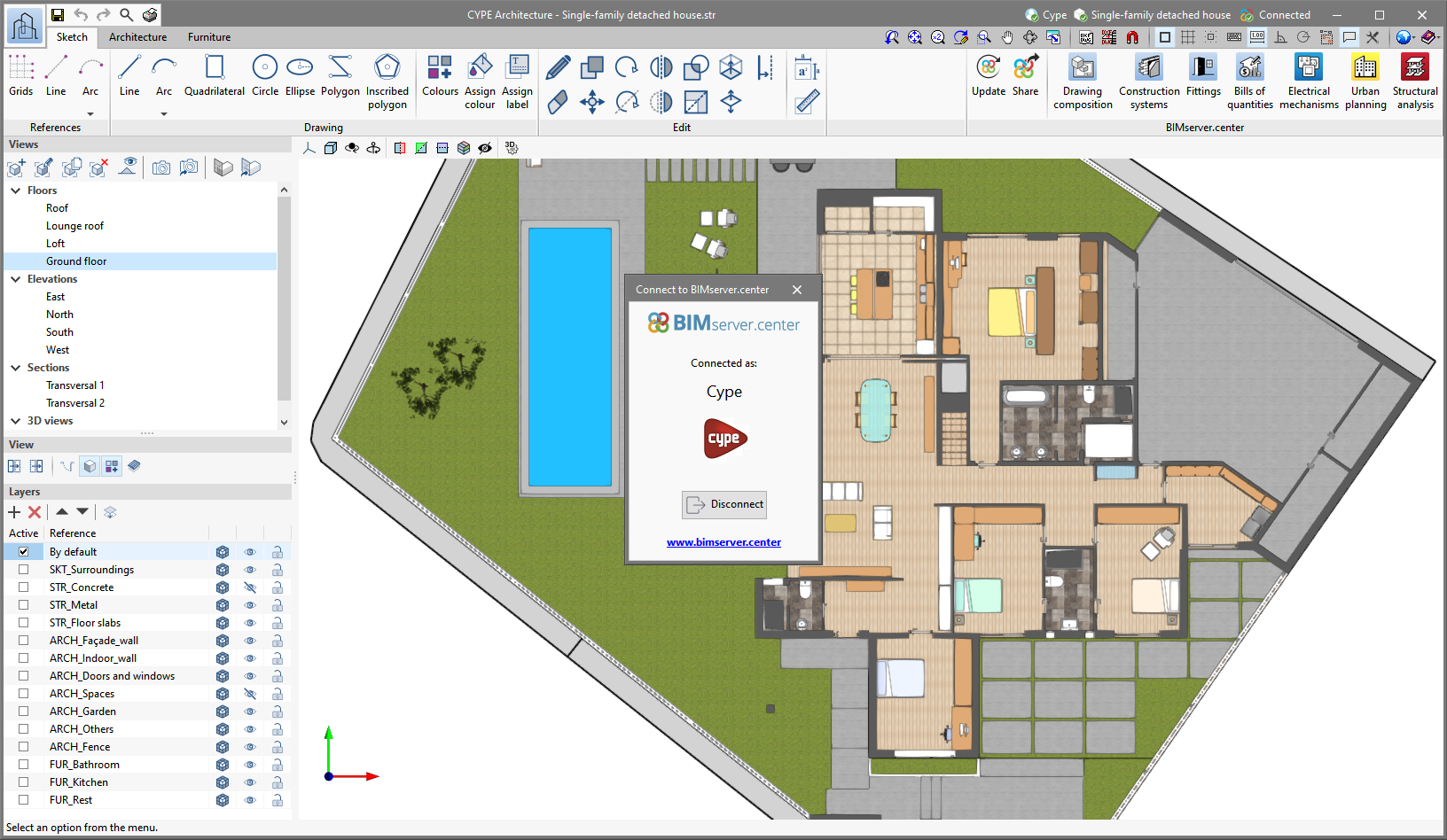
    The "BIMserver.center > Share" option panel has been improved, it was not displayed correctly at times when the screen resolution is small.

  • Sharing in BIMserver.center
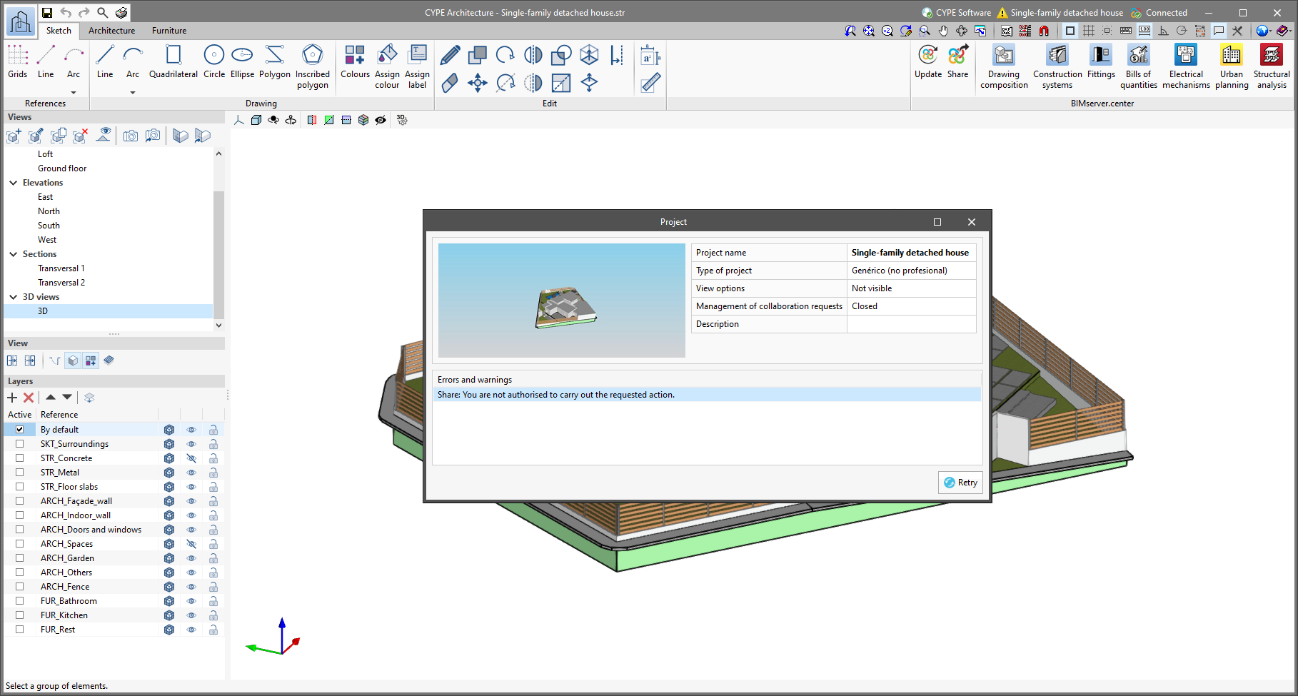
    An error that could occur in the "BIMserver.center > Share" option when generating the reinforcement for column starts has been fixed.

  • Punching shear check
    An error that occurred in the punching shear check process when there is a mat foundation with a very small surface in contact with a column has been fixed.

  • Deleting or dividing groups
    An error that occurred when deleting or dividing a group in the case of walls with blocked reinforcement has been fixed.

  • Beams information
    An error that occurred when selecting a wall that starts on top of another wall in the "Information - Beams" option has been fixed.

  • Bills of quantities
    The measuring of formwork for beams in the "Bills of quantities" option has been improved. In some cases, an element with a 0 m2 surface was added.

  • Changing a job’s code (EHE-08 to Código Estructural)
    The transformation of a job initially created with code EHE-08 when it is updated to code "Código Estructural" has been improved. As well as adapting the "Environment" selection in "General data", it is adapted in each beam that has a specific assignment.

  • Checking the baseline shear
    The checking of the base shear for walls without external fixity in contact with column starts with external fixity has been improved.

  • Checking geometry
    An error that occurred in the "Check the geometry of the current group" and "Check the geometry of the current group and higher groups" options, if sloped beams had been introduced in the job, has been fixed.

  • Analytical model
    An error that could sometimes occur when obtaining the analytical model of a wall whose axis did not match the centre and that ended in a sloped slab has been fixed.

  • Assign walls
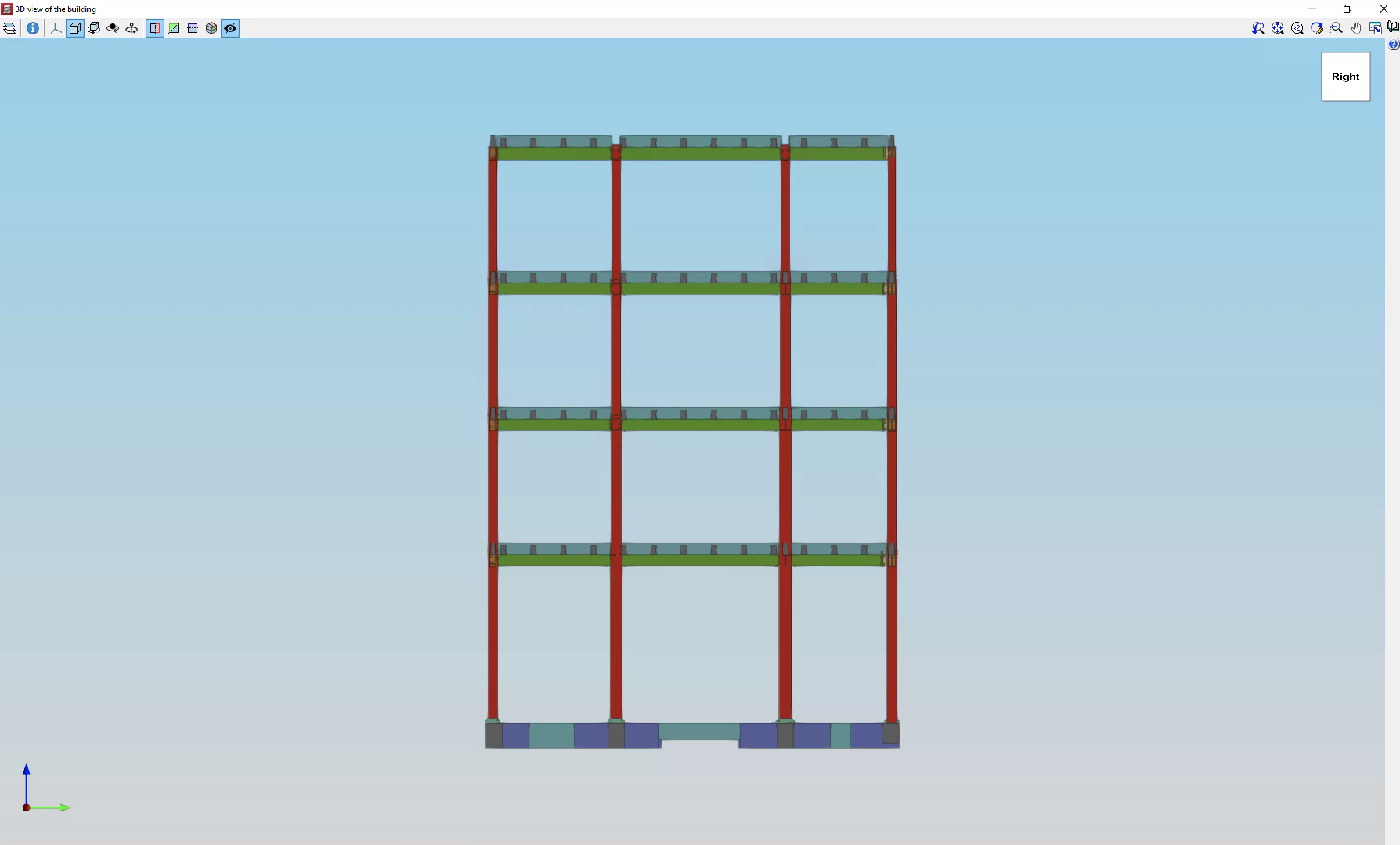
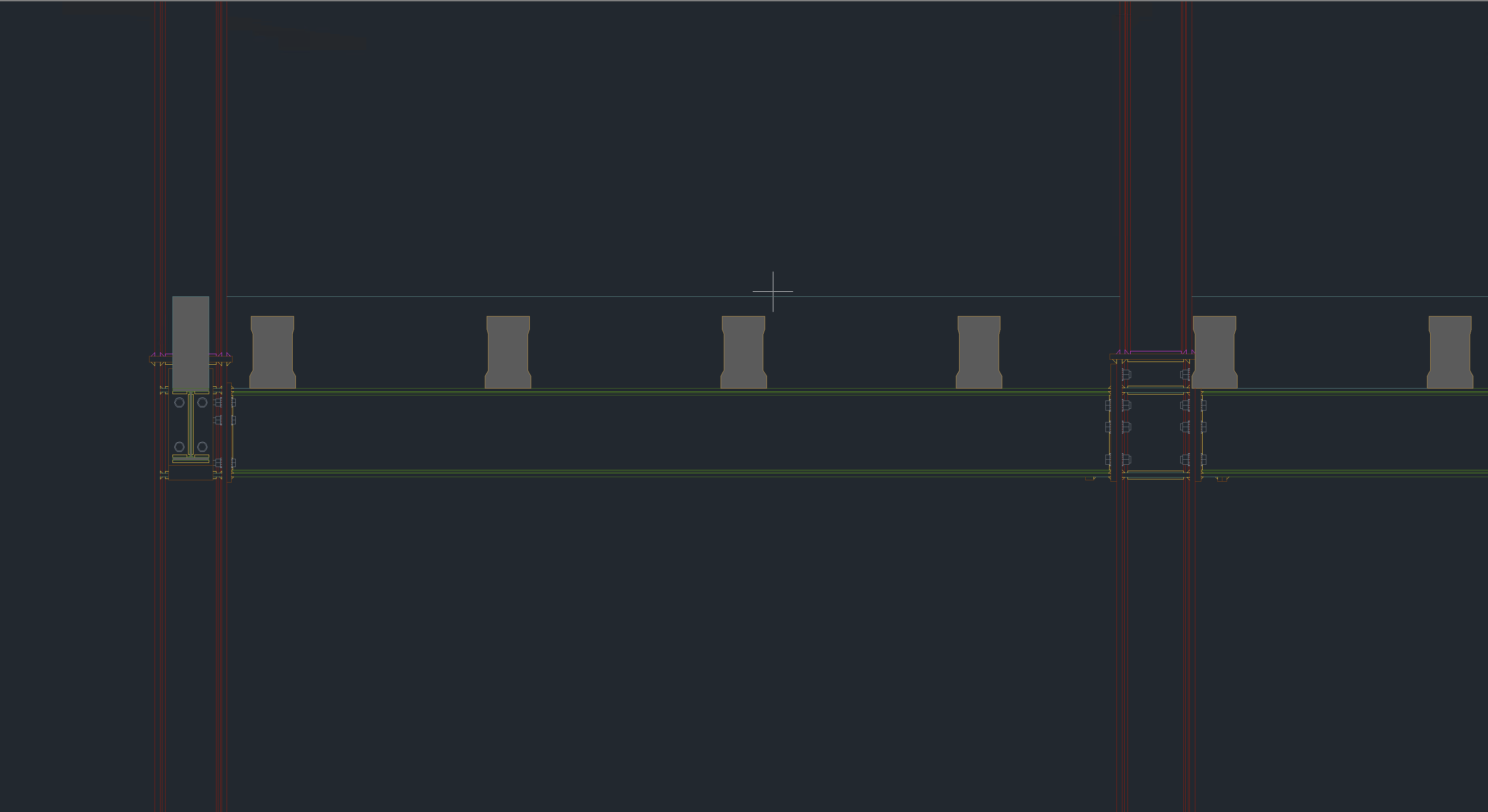
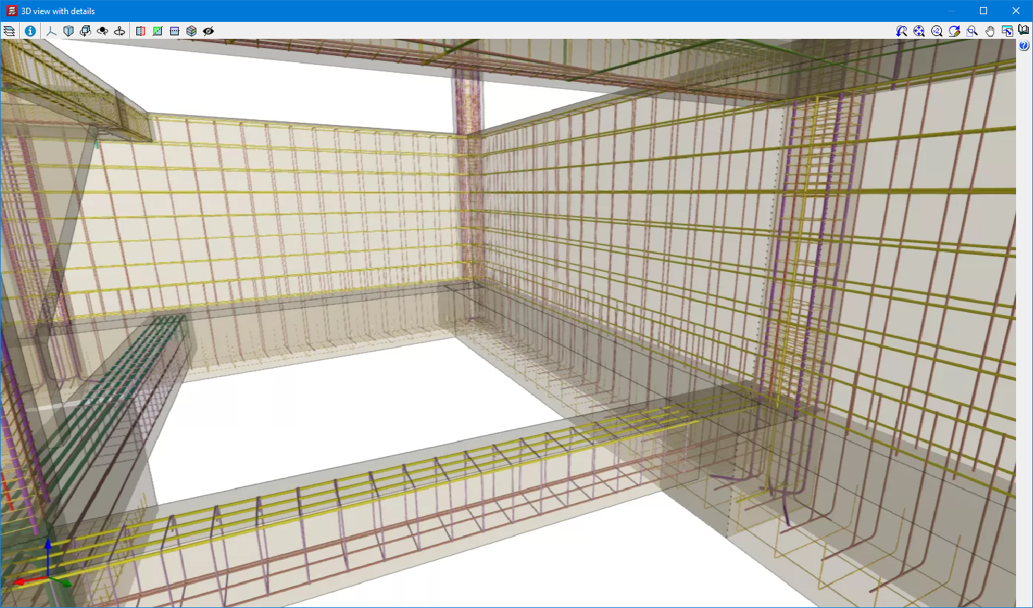
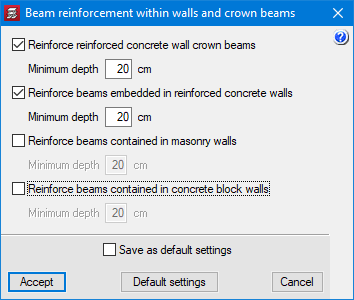
    The "Assign walls" option has been improved in order to consider embedded or crown beams with specific features.

In the "Add user information" option (Drawing editor - Details – Add user information), details can be created by importing an image. Up until the previous version (2022.d), details could only be created from DXF and DWG files. In the import process, the final size of the image in the drawing can be defined.

"Código Estructural (Real Decreto 470/2021)".

Implemented in CYPECAD and CYPE 3D for analysing and checking composite concrete and steel columns.

In previous versions, it was already implemented for analysing, designing or checking other structural elements:

  • For analysing and designing concrete structures (v.2022.c) in:
    • CYPECAD
    • CYPE 3D
    • Reinforced concrete cantilever walls
    • Embedded retaining walls

  • For analysing and checking steel connections (v.2022.c) in:
    • CYPE Connect
    • StruBIM Steel

  • For analysing and designing steel structures (v.2022.d) in:
    • CYPECAD
    • CYPE 3D

In the applications listed below, apart from the symbols included to represent elements that are introduced in their corresponding installations, symbols in DXF or DWG format can be imported:

  • CYPELEC Electrical Mechanisms
  • CYPEPLUMBING Water Systems
  • CYPEPLUMBING Sanitary Systems
  • CYPEPLUMBING Solar Systems
  • CYPEPLUMBING Schematic Diagram
  • CYPEHVAC

As of version 2022.e, applications that are connected to BIMserver.center communicate with the platform more directly. As a result, it is no longer necessary to specify the user account(s) and projects to be synchronised in the BIMserver.center Sync tool before using the applications. When a user signs in from a desktop application, it automatically establishes the connection to the project.

Previously, some applications required the user to connect to BIMserver.center and select a project in order to start a job. Now, this is no longer necessary and the link will only need to be established when updating the project or sharing a contribution.

As of version 2022.e, the applications connected to BIMserver.center have an information bar displaying the link status to the project on the platform. This bar can be found at the top right of the application window and is divided into the following sections:

  • User
    Displays the BIMserver.center user name that has been entered to access the application. If a connection has not been established with a platform user, the text "Connect" will appear. If the user clicks on this button, they will be able to type in their name and password, as well as sign out in order to access with other login credentials.
  • Project
    Displays the name of the BIMserver.center project linked to the job, if such a link exists. By clicking on this button, we can obtain additional information about the project, such as its description, project type or view options. If any warnings or errors occur when uploading or downloading contributions to the project, a list will be displayed in this panel with all the incidents detected. Furthermore, the project icon in the bar will change to a warning symbol.
  • Status
  • Displays the status of the connection with BIMserver.center.
  • When a contribution is being uploaded or downloaded, the text of the message changes and the progress of the action is displayed.
  • If an older version of the BIMserver.center Sync synchronisation tool is running, the message "Incompatible version of the BIMserver.center synchroniser" is displayed.
  • The synchroniser can be downloaded and installed free of charge from the BIMserver.center platform or installed during the installation process of the applications. The latest version of the tool is required for applications to be able to display status messages.

Version 2022.h of CYPECAD includes minor improvements and corrections of the program that could occur in certain cases:

  • The editing of the beam assembly reinforcement tables is improved in order to allow the same entry to be used in different width and/or depth ranges.
  • An error that could occur when designing the reinforcement of hollow core plates when they form part of a roof with several sloped planes has been fixed.

The options for exporting 3D views to 2D DXF and DWG formats have been implemented. The dialogue box containing these new options can be accessed from the "Print the current view" button, in the top bar of the 3D views.

If a scene has defined cutting planes or volumes, filling polygons can be generated on the elements that are cut by these planes or volumes.

This can be carried out by activating the "Generate polygons with infill in the cuts by planes" option.


CYPECAD exports a BIM model to a project on the BIMserver.center platform which includes the quantities related to certain structural elements, among other things. As a result, programs such as Open BIM Quantities can use these quantities to generate the bill of quantities for these elements. These quantities are exported using the standardised IFC format.

In version 2022.g, the number of quantities associated with construction elements that can be exported has been extended. CYPECAD now exports the following quantities, which are listed by construction element and indicating the IFC entity that it contains:

  • Walls (entity “IfcWall”, set of quantities “Qto_WallBaseQuantities”)
    • Length (“Length”)
    • Width (“Width”)
    • Height (“Height”)
    • Gross footprint area (“GrossFootprintArea”)
    • Net footprint area (“NetFootprintArea”)
    • Gross side area (“GrossSideArea”)
    • Net side area (“NetSideArea”)
    • Gross volume (“GrossVolume”)
    • Net volume (“NetVolume”)

  • Slabs ( entity ”IfcSlab”, set of quantities ”Qto_SlabBaseQuantities”)
    • Width (“Width”)
    • Length (“Length”)
    • Depth (“Depth”)
    • Perimeter (“Perimeter”)
    • Gross area (“GrossArea”)
    • Net area (“NetArea”)
    • Gross volume (“GrossVolume”)
    • Net volume (“NetVolume”)
    • Gross weight (“GrossWeight”)
    • Net weight (“NetWeight”)

  • Beams (entity ”IfcBeam”, set of quantities ”Qto_BeamBaseQuantities”)
    • Length (“Length”)
    • Cross section area (“CrossSectionArea”)
    • Outer surface area (“OuterSurfaceArea”)
    • Gross volume (“GrossVolume”)
    • Net volume (“NetVolume”)

  • Columns (entity ”IfcColumn”, set of quantities ”Qto_ColumnBaseQuantities”)
    • Length (“Length”)
    • Cross section area (“CrossSectionArea”)
    • Outer surface area (“OuterSurfaceArea”)
    • Gross volume (“GrossVolume”)
    • Net volume (“NetVolume”)

  • Footing (entity ”IfcFooting”, set of quantities ”Qto_FootingBaseQuantities”)
    • Length (“Length”)
    • Width (“Width”)
    • Height (“Height”)
    • Gross volume (“GrossVolume”)
    • Net volume (“NetVolume”)
    • Gross weight (“GrossWeight”)
    • Net weight (“NetWeight”)

  • Piles (entity “IfcPile”, set of quantities “Qto_PileBaseQuantities”)
    • Cross section area  (“CrossSectionArea”)

In order to export the quantities, the complete analysis of the job must be carried out and the "Quantities" option must be selected in the "Share" dialogue box, which appears when clicking on the "Share" option in the "BIMserver.center" menu.

CYPECAD version 2022.g allows the reinforcement of concrete walls to be exported to the BIM project.

Therefore, the concrete elements that export their reinforcement to the BIM project up to this version are:

  • Concrete walls
  • Beam frames
  • Columns
  • Corbels
  • Foundation elements
    Footings, pile caps, strap beams and tie beams.
  • Floor slabs
    Joist floor slabs, waffle slabs, hollow core plate floor slabs, composite slabs and flat slabs.

This reinforcement, along with the reinforcement exported from StruBIM Shear Walls, can be viewed in the StruBIM Rebar program.

They can also be viewed in the "Results" tab (Groups menu > 3D view with details).

In previous versions, crown beams could be defined in concrete walls. As of version 2022.g, embedded beams can also be defined at the level of each intermediate floor.

As of version 2022.g, the service class can be defined individually for each timber element (columns, beams and joist floor slabs).