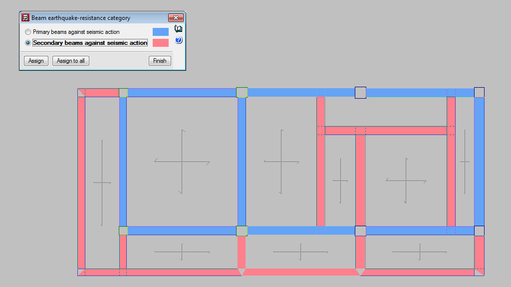
In the seismic analysis of the structure, CYPECAD can design structural beams as primary or secondary beams, depending on their role in the earthquake-resistant structure (Beam Definition > Beams/Walls > Secondary beams). Secondary beams are not considered as being part of the structural system to resist seismic loads hence, these elements do not need to be designed specifically for that.
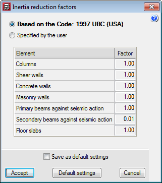
The stiffness of the secondary beams, for seismic loadcases, is reduced depending on the value defined in the “Inertia reduction factors” dialogue box (“Project” > “General options”). The mass of the secondary beams is taken into account.
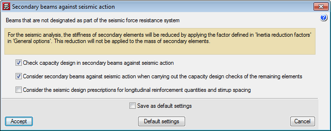
As for the capacity checks, users can indicate how the secondary beams are to be considered depending on their judgement. The following options can be activated in the “Secondary beams against seismic action” dialogue box (“Project” > “General data” > “Design options for steel bars” > “Beam options” “Design/Code check”):
- Check capacity design in secondary beams against seismic action.
- Consider secondary beams against seismic action when carrying out the capacity design checks of the remaining elements.
- Consider seismic design prescriptions for longitudinal reinforcement quantities and stirrup spacing.