Partial fixity coefficient at beam ends
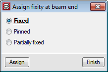
In the 2017.a version of CYPECAD, users can introduce a partial fixity coefficient at the end of a concrete beam. To do so, the option: “Fixity at beam end” (Beam Definition tab > “Beams/Walls”) has been implemented, which opens a dialogue box in which users can indicate that the beam end is:
- Fixed (default option)
- Pinned
- Partially fixed
Users can introduce a numerical value between “0” (pinned) and “1” (fixed).
When this option is selected, symbols are drawn, in a different colours and shapes, at the ends of the beams to indicate which option has been applied.
In previous versions, beam ends could be pinned or fixed using the “Pin/Disconnect” option which is also used to disconnect columns from wall-support type beams. Now this option is only used to disconnect columns and is now called “Disconnect/Connect”.
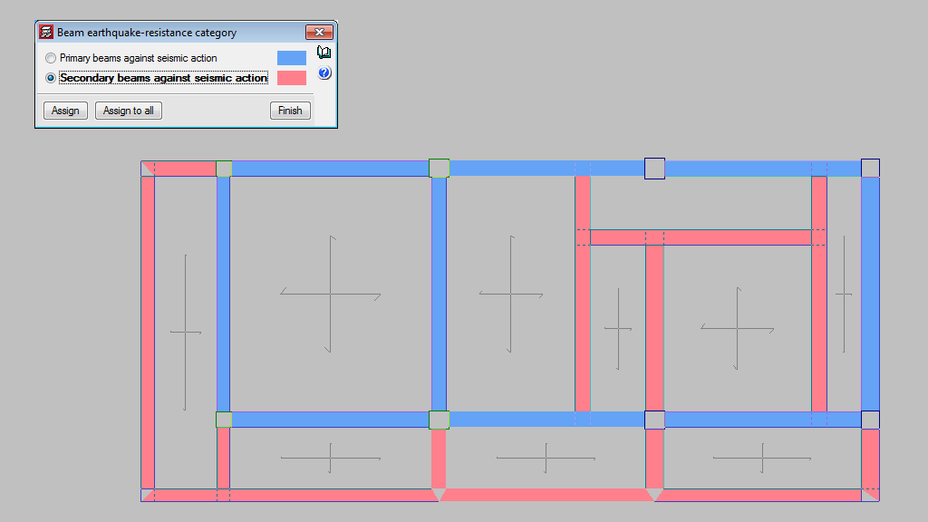
Earthquake resistance category of beams
In the seismic analysis of the structure, CYPECAD can design structural beams as primary or secondary beams, depending on their role in the earthquake-resistant structure (Beam Definition > Beams/Walls > Secondary beams). Secondary beams are not considered as being part of the structural system to resist seismic loads hence, these elements do not need to be designed specifically for that.
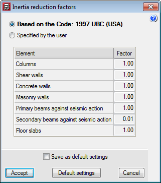
The stiffness of the secondary beams, for seismic loadcases, is reduced depending on the value defined in the “Inertia reduction factors” dialogue box (“Project” > “General options”). The mass of the secondary beams is taken into account.
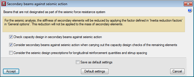
As for the capacity checks, users can indicate how the secondary beams are to be considered depending on their judgement. The following options can be activated in the “Secondary beams against seismic action” dialogue box (“Project” > “General data” > “Design options for steel bars” > “Beam options” “Design/Code check”):
- Check capacity design in secondary beams against seismic action.
- Consider secondary beams against seismic action when carrying out the capacity design checks of the remaining elements.
- Consider seismic design prescriptions for longitudinal reinforcement quantities and stirrup spacing.
Continuity of joists (steel and timber)
The joists of adjacent panel can now be assigned as being continuous, for steel and timber joists. This way, the program will design each continuous joist of both panels as if it were a single element.
In previous versions, when steel joists (and now timber joists) were introduced, the panel were designed independently, and the joists were assumed to be simply supported, except in the case of overhangs, where they were automatically fixed in order to maintain equilibrium. In this case, if the joists have a design error, the program will indicate that it is not possible to design the joist as a continuous element.
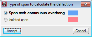
As of the 2017.a version, the program allows users to assign continuity to joists of the panels selected by users. In the “Type of span to calculate the deflection” (Slabs > “Joist continuity”) dialogue box, CYPECAD allows users to select two types of continuity for steel and timber joists:
- Span with continuous overhang
It is to be used for joist overhangs, so the joists have continuity. - Isolated span
This option is to be used to join two continuous panels, so the program treats the two joists as if it were a single element.
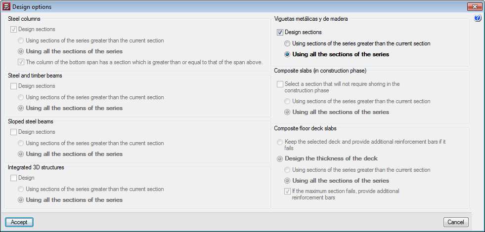
It is important to note that in the analysis of the panels with continuity, due to differences in stiffness, the results will not be the same if the analysis is carried out with the first section of the series or if the analysis begins with an intermediate section. Therefore, as occurs with the design of other steel and timber elements, an option has been added for steel and timber joists in the “Design options” dialogue box (which appears once the “Analyse” option has been selected when there are steel or timber elements present).
Timber beams
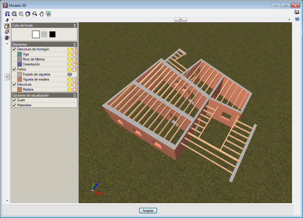
Users can, as of previous versions, introduce generic-type structural timber elements in the integrated structures of CYPECAD and CYPE 3D using the “Timber sections” module.
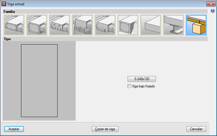
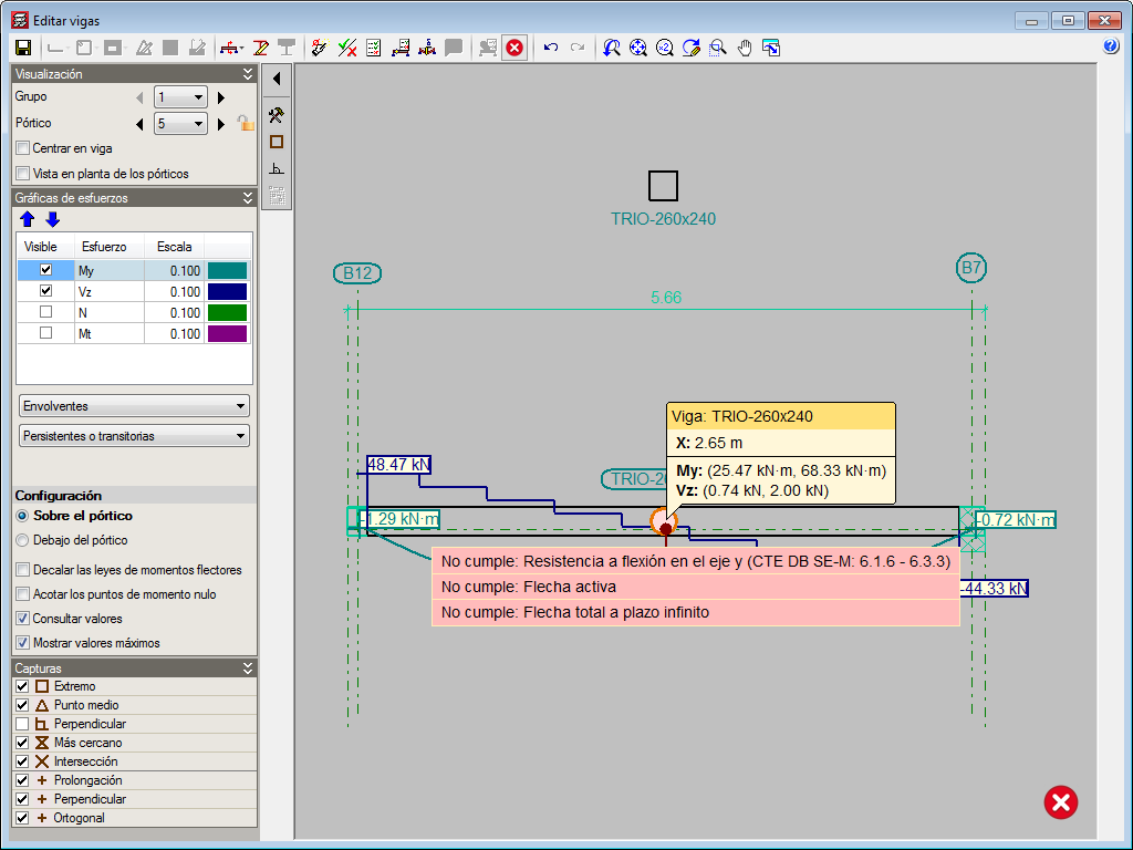
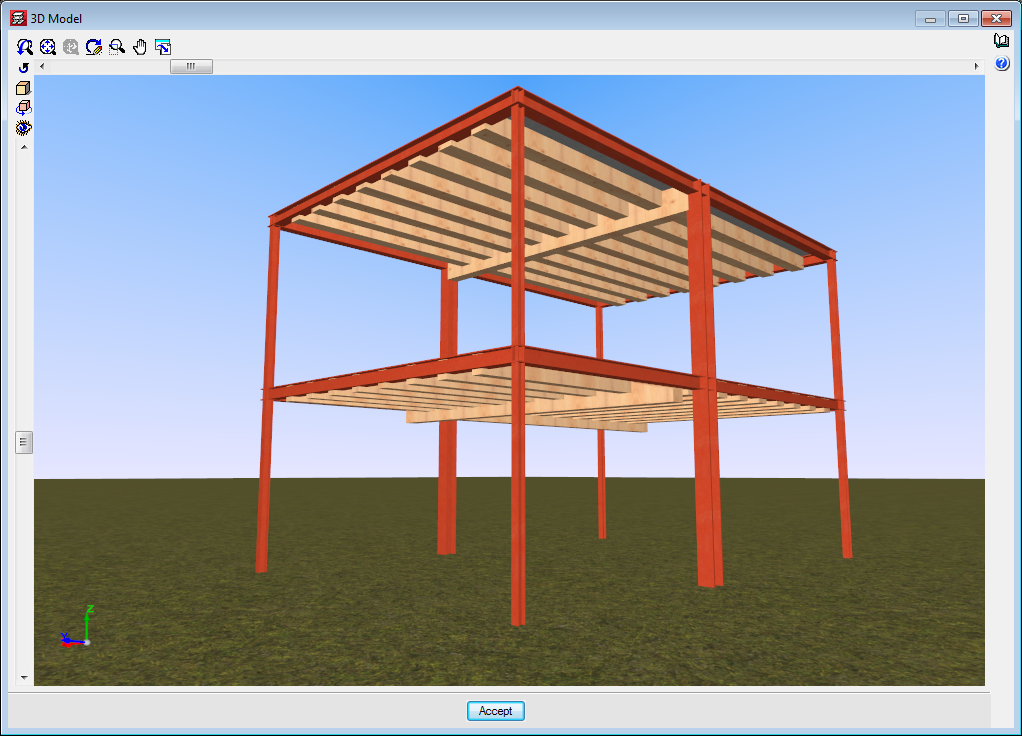
In the 2017.a version, the “Timber sections” module has further features and allows users to introduce beam-type structural timber elements in CYPECAD and CYPE 3D. By introducing the timber beams as that type of structural element instead of generic timber beams, allows specific beam checks to be carried out, and use the “Advanced beam editor” to edit and design these elements.
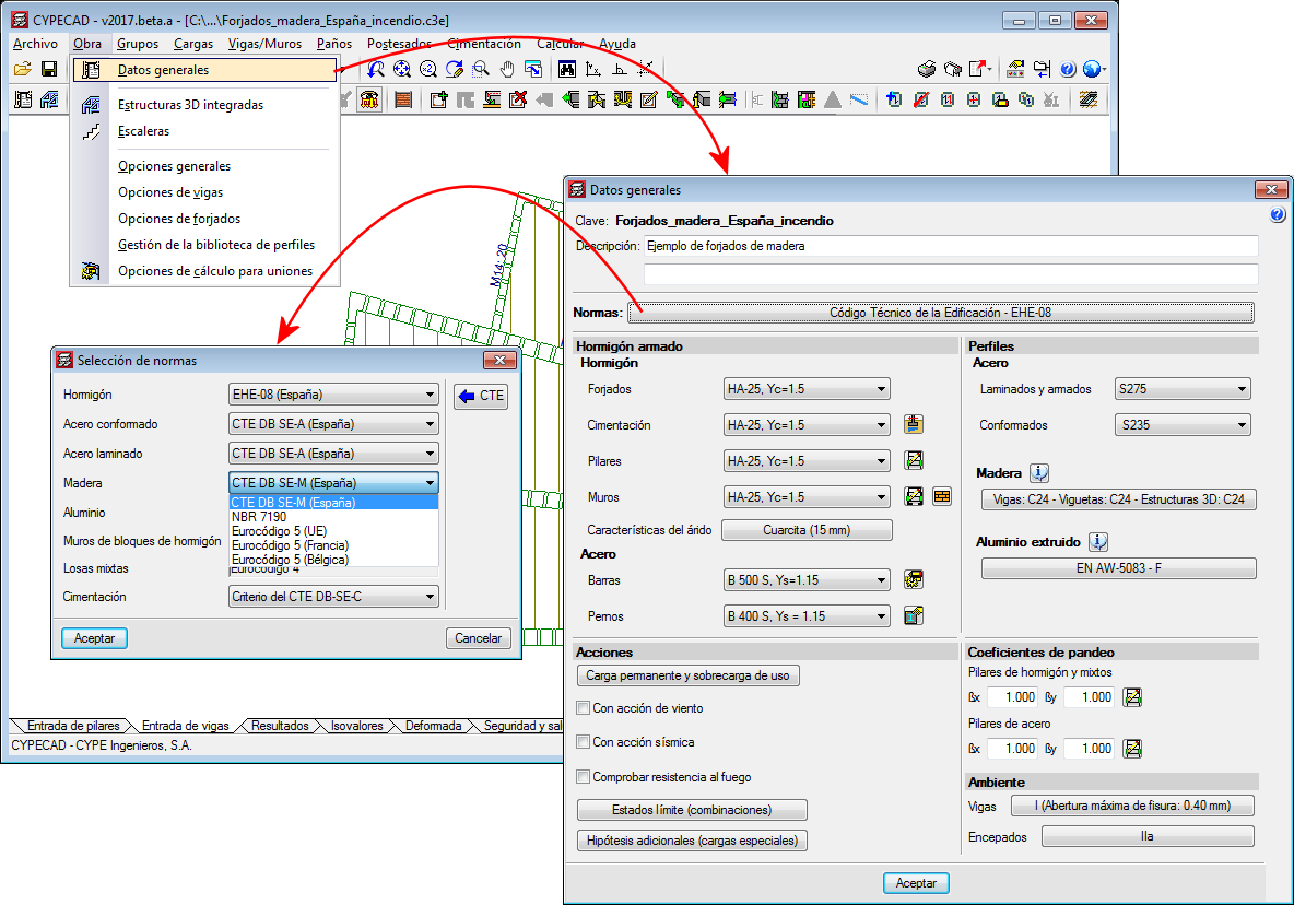
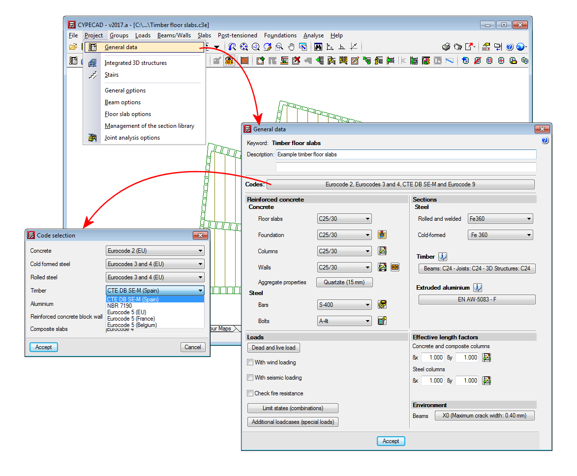
The codes implemented for the design and check of the timber joist floor slabs and beams are:
- CTE-DB -SE-M (Spain)
- Eurocode 5
- Eurocode 5 France
- Eurocode 5 Belgium
- NBR 7190:1997 (Brazil)
To adapt the program to the current market, timber sections have been created, distinguishing between sawn timber and laminated timber, and including the DUO/TRIO series, which are currently very much in use.
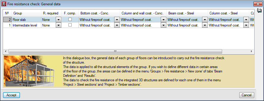
CYPECAD and CYPE 3D also carry out a fire resistance check for timber beams using the “Fire resistance check” module.
For CYPECAD and CYPE 3D to be able to analyse and design timber beams and generic timber bars, the user licence must include, as well as the permits corresponding to CYPECAD and/or CYPE 3D, the “Timber beams” module. If, users also wish to check the fire resistance of these elements, they must also hold the “Fire resistance check” module permits.
More information on the introduction, analysis and design of timber beams in CYPECAD and CYPE 3D can be found on the “Timber sections” webpage.
Timber joist floor slabs
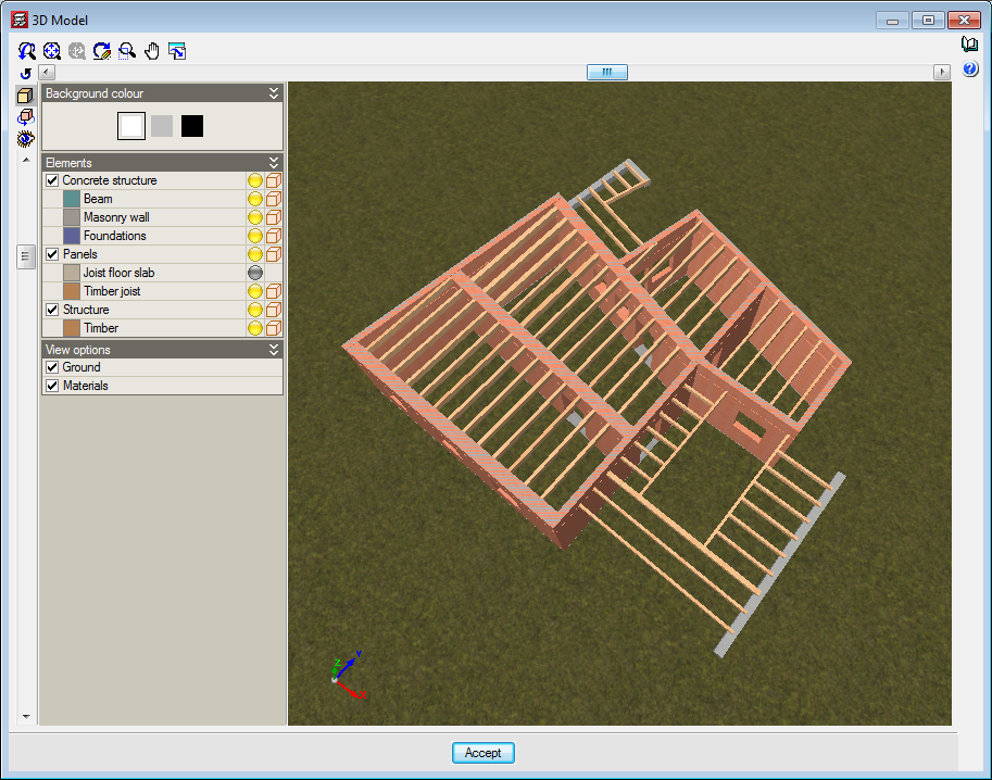
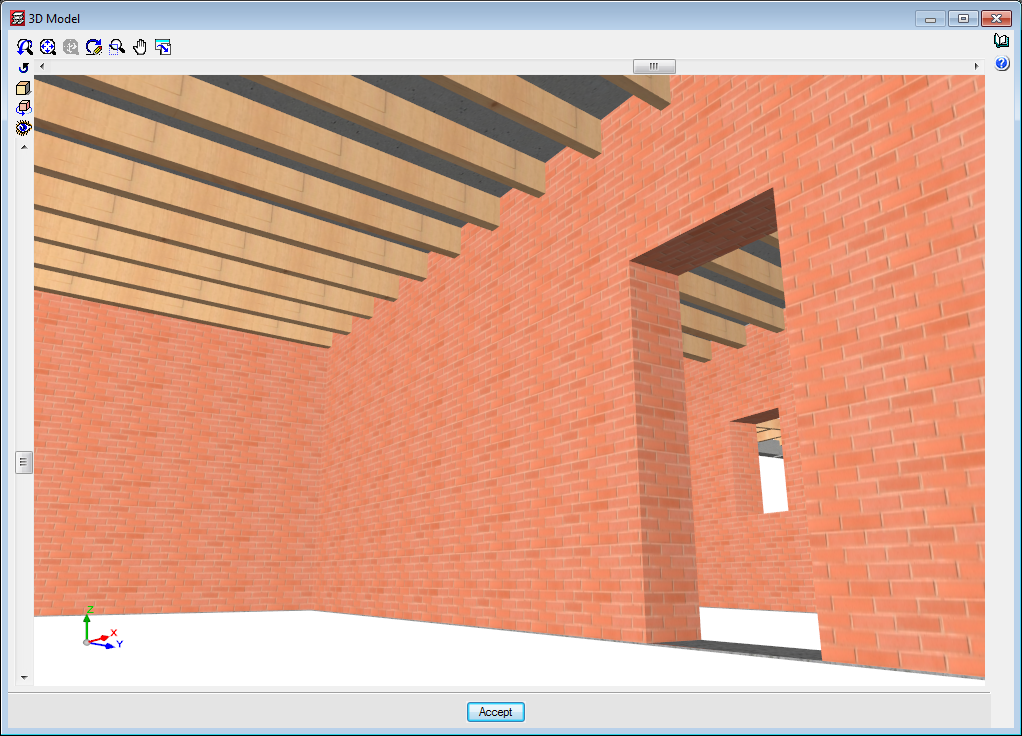
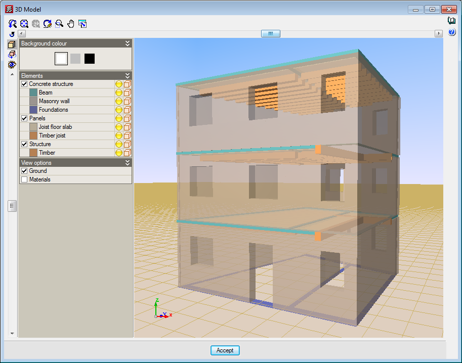
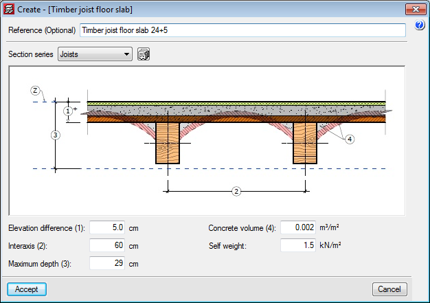
The “Timber joist floor slabs” module has been implemented in the 2017.a version, with which CYPECAD analyses and designs timber joist floor slabs.
The codes implemented for the design and check of the timber joist floor slabs and beams are:
- CTE-DB -SE-M (Spain)
- Eurocode 5
- Eurocode 5 France
- Eurocode 5 Belgium
- NBR 7190:1997 (Brazil)
To adapt the program to the current market, timber sections have been created, distinguishing between sawn timber and laminated timber, and including the DUO/TRIO series, which are currently very much in use.
The sections that make up the timber joists are designed for simple bending, because due to the rigid diaphragm hypothesis, axial forces and forces in the plane of the floor slab are not considered.
The deflection checks for timber joists are obtained considering the deflection limits for the joist defined by users and the active deflection and long-term deflection.
CYPECAD also carries out a fire resistance check for timber beams using the “Fire resistance check” module.
For CYPECAD to be able to analyse and design joist floor slabs, the user licence must include, as well as CYPECAD, the “Timber joist floor slabs” and “Joist floor slabs (generic concrete beams)” modules. If, users also wish to check the fire resistance of these elements, they must also hold the “Fire resistance check” module permits.
More information on the introduction, analysis and design of timber joist floor slabs in CYPECAD can be found on the “Timber joist floor slabs” webpage.
Timber sections (existing module that now designs timber beams in CYPECAD and CYPE 3D)
As of previous versions, users have been able to introduce “Generic” structural timber elements in integrated 3D structures in CYPECAD and CYPE 3D using the “Timber sections” module.
Further features have been added to the “Timber sections” module with the 2017.a version. Now, users can introduce beam-type timber elements in CYPECAD and CYPE 3D. By introducing the timber beams as that type of structural element instead of generic timber beams, allows specific beam checks to be carried out, and use the “Advanced beam editor” to edit and design these elements.
A summarised description of this new feature of the “Timber sections” module can be found in the “Timber beams” section of the new features of CYPECAD.
More information on the introduction, analysis and design of timber beams in CYPECAD and CYPE 3D can be found on the “Timber sections” webpage.
Timber joist floor slabs (CYPECAD module)
The “Timber joist floor slabs” module has been implemented in the 2017.a version, with which CYPECAD analyses and designs timber joist floor slabs.
A summarised description of this module can be found in the “Timber joist floor slabs” section of the new features of CYPECAD.
More information on the introduction, analysis and design of the timber joist floor slabs can be found on the “Timber joist floor slabs” webpage.
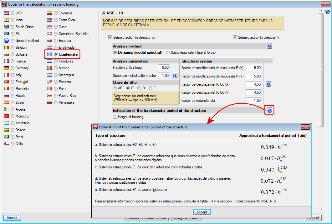
Seismic code of Guatemala (NSE – 10)
The help text of the section that explains that the estimated fundamental period of the structure is determined using simplified formulae, depending on the structural type, has been corrected due to errors published in the code; type E1 has been changed for E2 and vice-versa.