The 2020.a version of CYPELEC Core includes two new ways to identify and differentiate the three phases of a three-phase electrical system. These are: "R Y B" and "R G B".
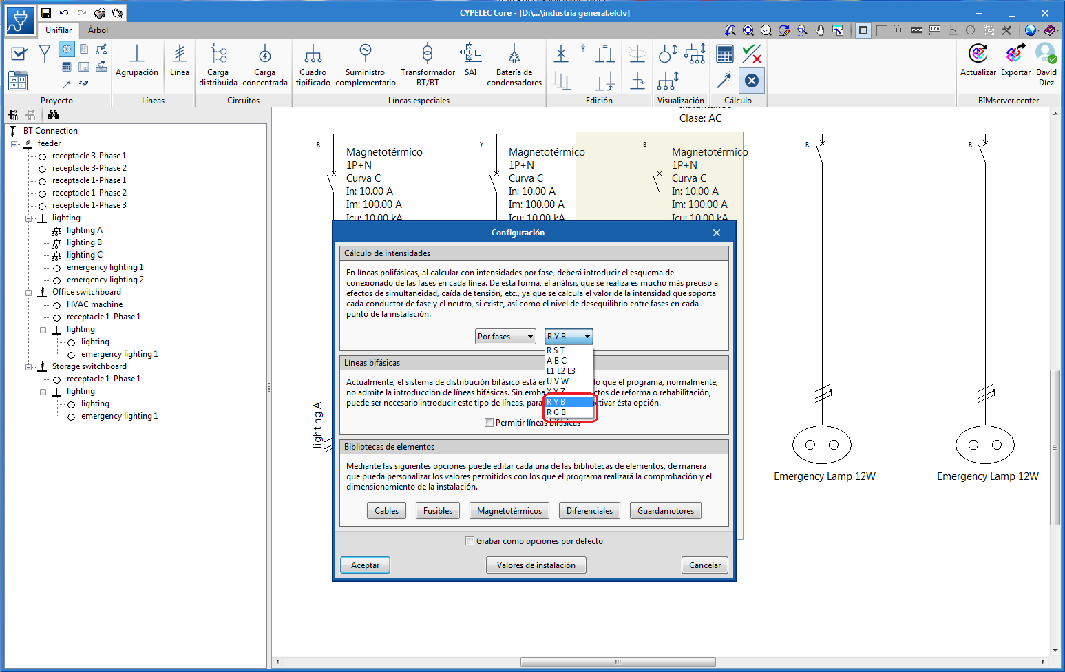

The 2020.a version of CYPELEC Core includes two new ways to identify and differentiate the three phases of a three-phase electrical system. These are: "R Y B" and "R G B".
As of the 2019.f version, CYPE programs (those downloaded from our website and those downloaded from the BIMserver.center platform) are compiled for 64-bit systems. The 64-bit compilation of CYPE software implies the use of the superior features of 64-bit processors and operating systems compared to those of 32 bits.
Please bear in mind that you must have a 64-bit operating system to be able to work with any 64-bit software.
In any case and as a temporary measure, the 2019.f version is available in 64 and 32 bits on the download area of our webpage. The programs that can be downloaded from the BIMserver.center platform are only available in 64 bits. If you have a 64-bit operating system, you can work with either the 64-bit and 32-bit version of our software, although we strongly recommend that you install the 64-bit CYPE software version.
You can see which operating system is installed on your computer by clicking on "Control panel > System".
Since 64-bit microprocessors began to be massively introduced into personal computers from 2003 and from the Windows XP version, Microsoft already offers the two versions of its operating systems (32 and 64 bits). We understand that almost all our users will have computers with 64-bit processors (x64) and 64-bit operating systems.
It could occur that a user may wish to work with a computer with a 64-bit processor but with a 32-bit operating system. It would be very strange if the computer had a 32-bit processor (x86 - computers over 15 years old). If any of these is your case, we advise you to talk to your hardware or software provider to update your situation as soon as possible. However, you can download the 32-bit version and work with CYPE programs that can be downloaded from our website until your situation is up-to-date.
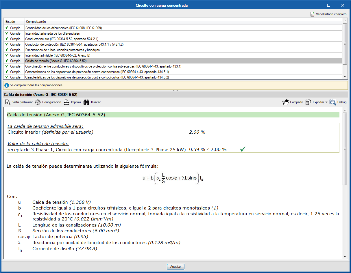
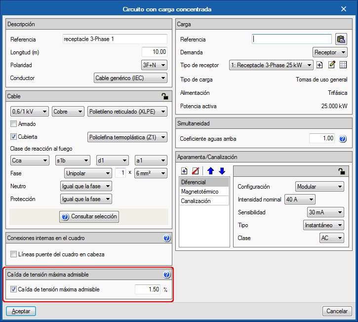
As of previous versions, CYPELEC Core allowed users to activate the maximum allowable voltage drop check for a specific line using the option indicated in the image.
As of the 2019.b version, this limitation becomes a design criterion, in other words, the program will increase the section to comply with the imposed limit.
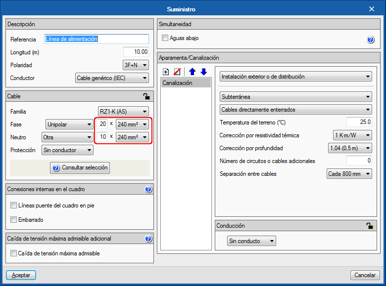
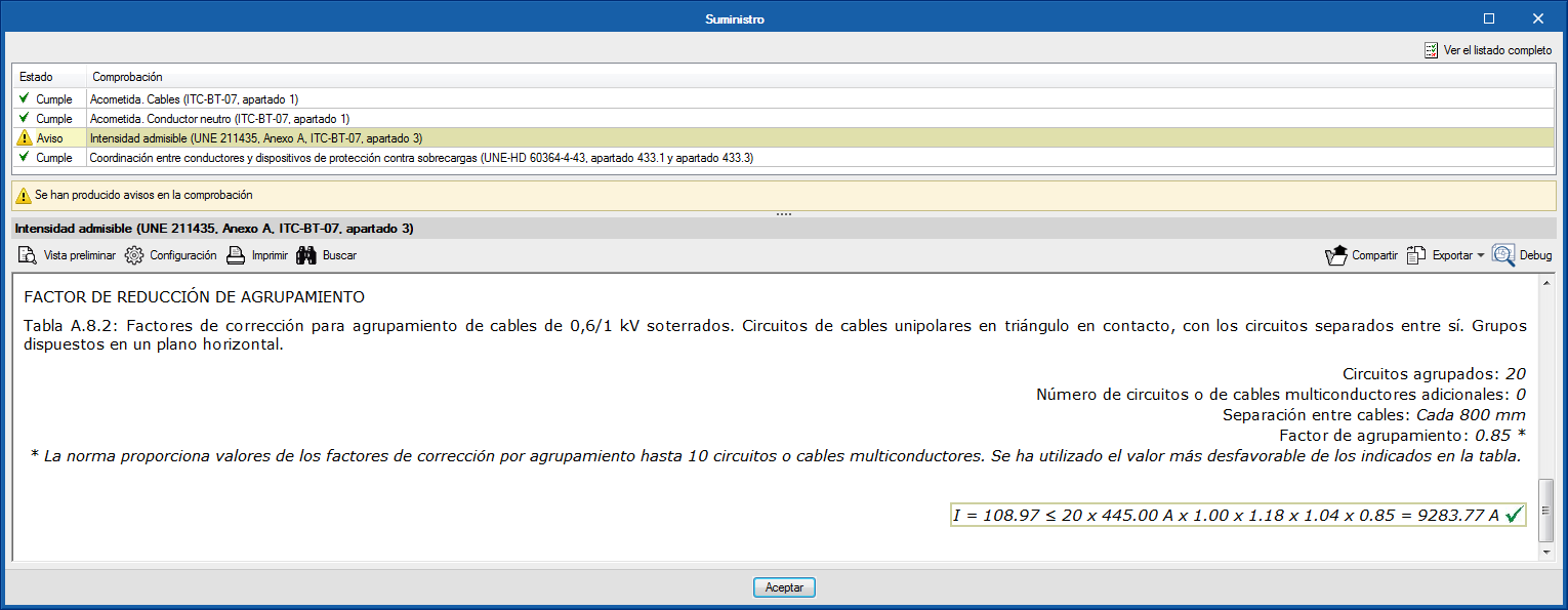
The group correction factors of all the installation methods corresponding to the UNE 211435 and IEC 60364-5-52 codes have been checked, to increase the number of conductors per pole (number of circuits) from 9 to 20.
It is possible that some tables, for certain installation methods, do not provide a group correction factor for a high number of conductors, in which case the program uses the most unfavourable factor amongst those indicated in the table, and indicates it with a warning message when checking the maximum admissible current or ampacity.
This increase allows users to use, for example, cables of over 2500 A for transformer outputs.
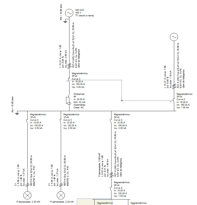
As of the 2019.b version, CYPELEC Core, CYPELEC NF and CYPELEC REBT allow for the electrical supply to be provided by two generators connected in parallel, one of which configured as the main supply and the other a complementary supply, to provide for all the installation.
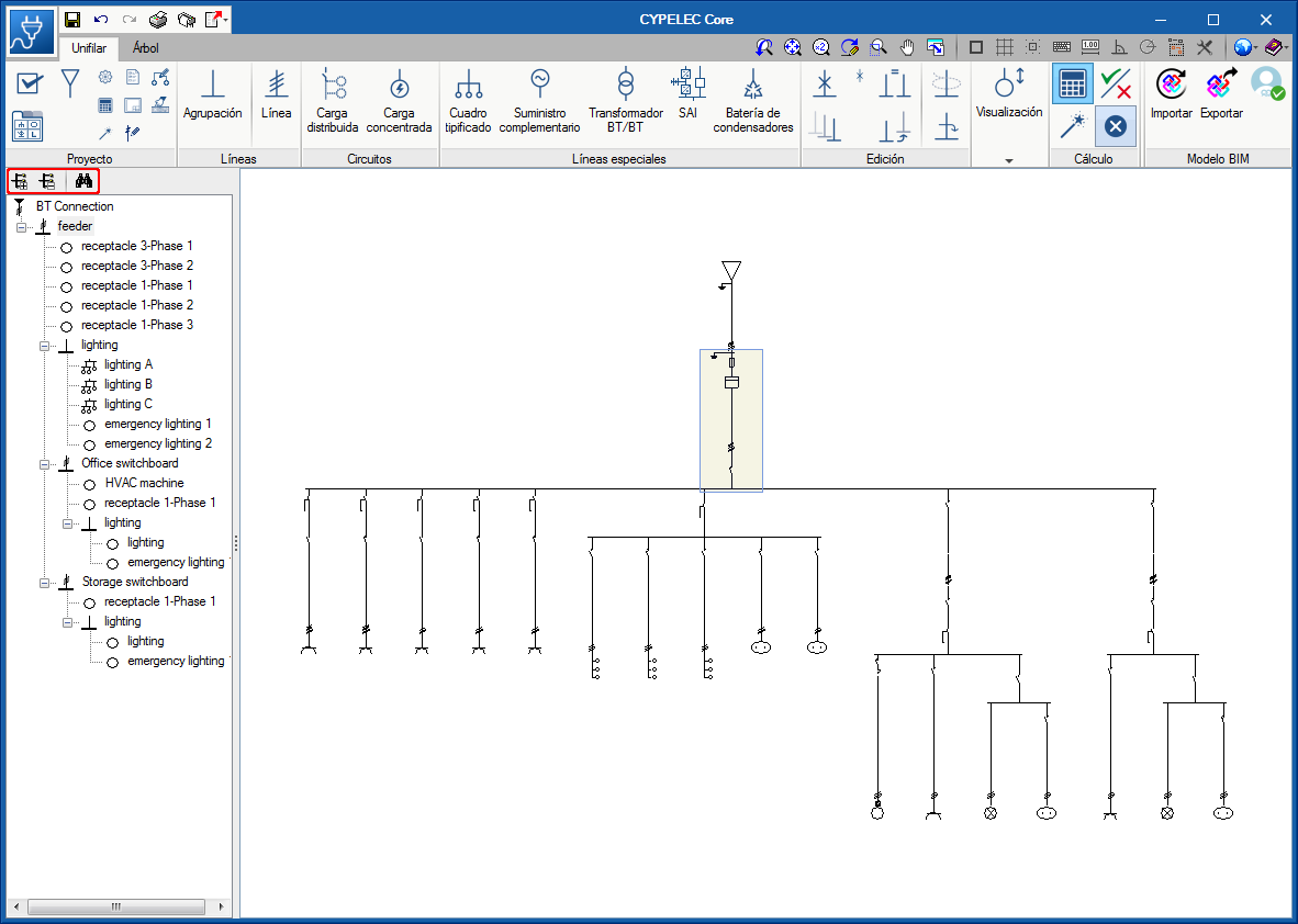
In the “Single line” tab, a toolbar has been added in the part above the tree structure of the installation that allows users to expand and contract the diagram, and search lines of the single-line diagram. When a specific line is sought, the line that is found is indicated in the tree structure and highlighted in the diagram.
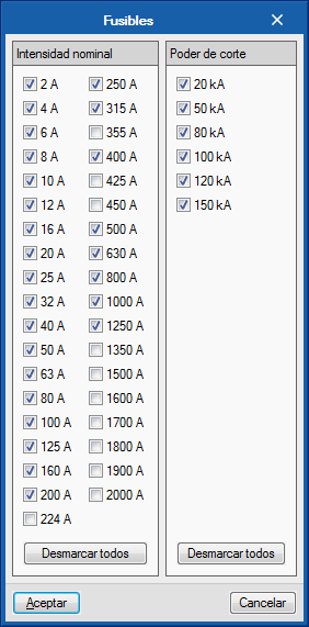
Nominal current fuses: 224 A, 355 A and 450 A, have been added. This selection is deactivated by default. It can be activated in “Configuration” > “Elements library” > “Fuses”. This way, the new currents will be available when the fuses are edited.
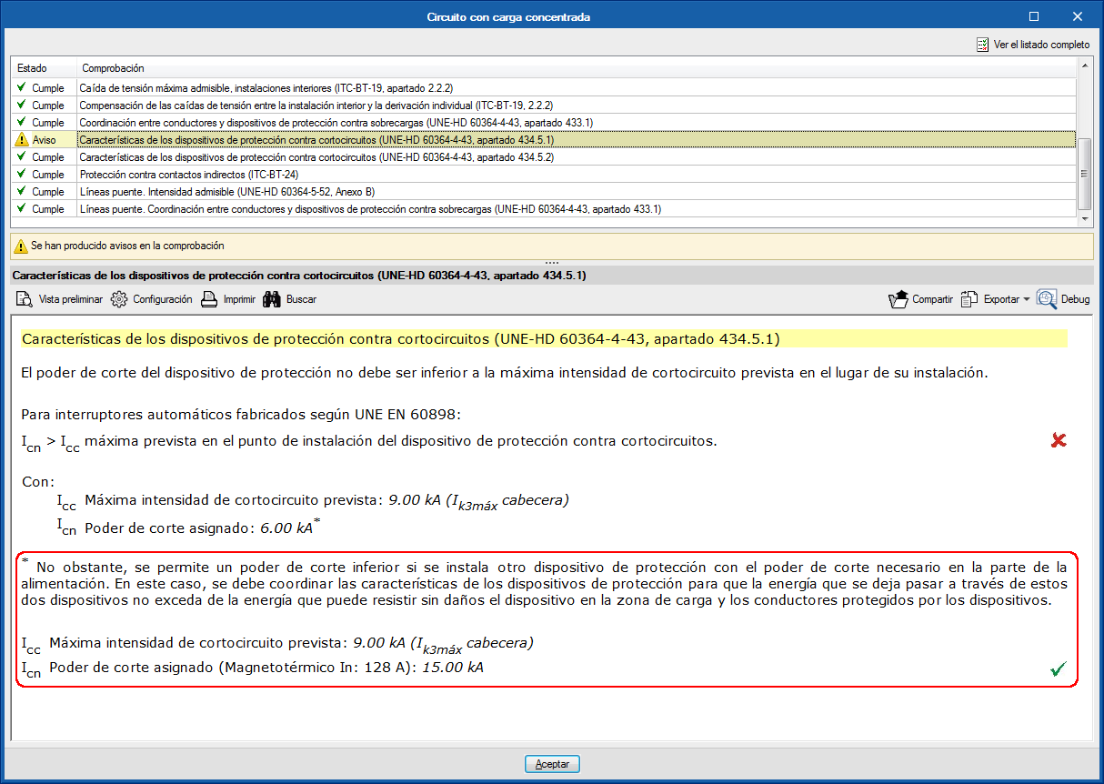
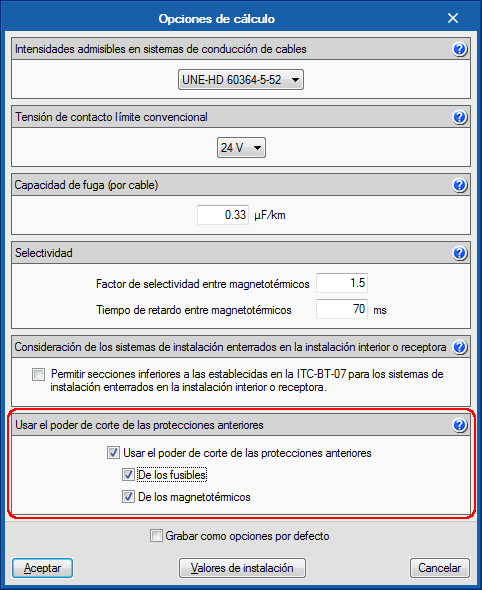
Section 434.5.1 of the UNE-HD 60634-4-43 code allows users to use a lower breaking capacity of the protection device of the loading zone if another protection device is installed before with the required breaking capacity. It is a solution for circuits that start at distribution panels that are close to transformers.
As of the 2019.a version, CYPELEC REBT, CYPELEC NF and CYPELEC Core contemplate the possibility of using the breaking capacity of previous protection devices in the design options. The breaking capacity can be that of the fuses or circuit breakers depending on the selection.
The check report includes a comment on the matter in case this option has been used.
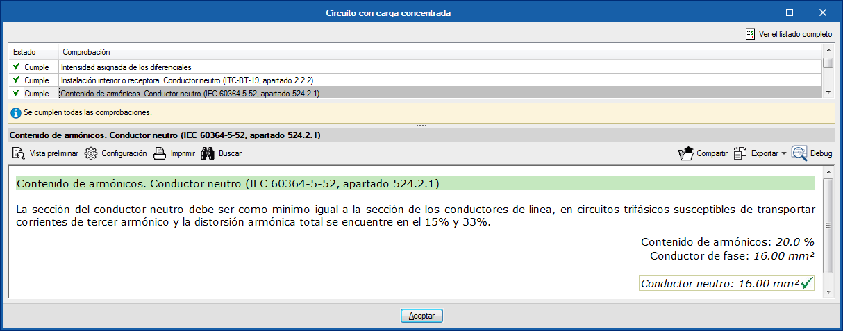
The 2019.a version of CYPELEC REBT, CYPELEC NF and CYPELEC Core include the check of the neutral section due to the possible contents of harmonics in three-phase circuits, in accordance with the international code: IEC 60364-5-52, section 524.2.1.
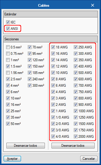
The 2019.a version of CYPELEC Core allows users to select AWG (American Wire Gauge) cables.
These cables can be selected in the “Cables” dialogue box (“Configuration” button in the toolbar > “Element library” > “Cables”), where users can choose, as well as the calibres that were available in previous versions, calibres 18 AWG to 2000 AWG.
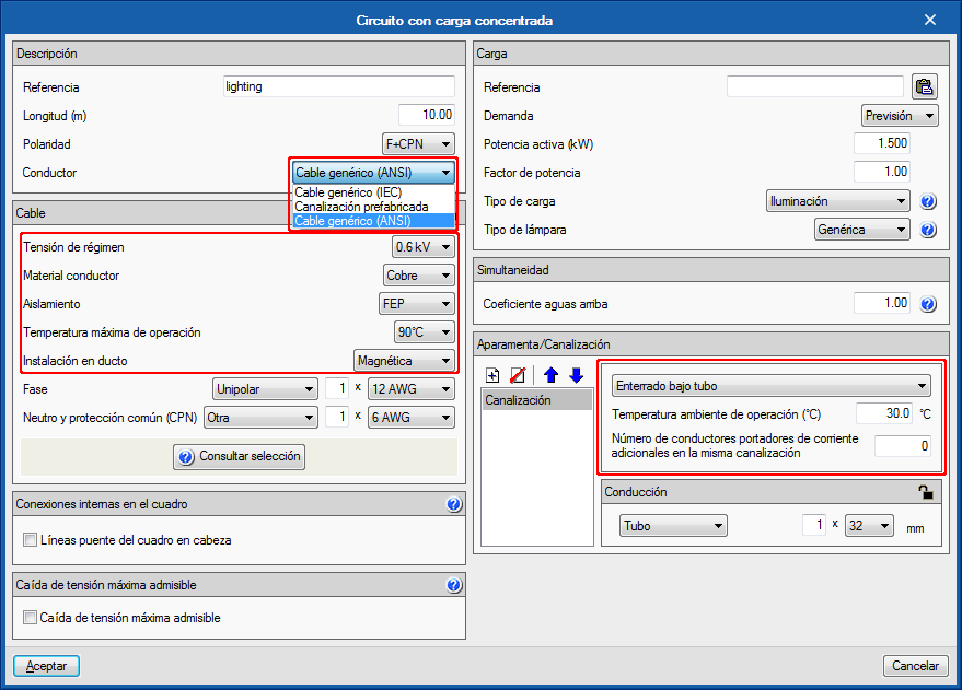
When the AWG cable selection is activated, their selection is enabled in the line editing panels.
The panel adapts to the selected type of cable (IEC or AWG), in terms of the parameters that define the cable, type of channel and installation method.
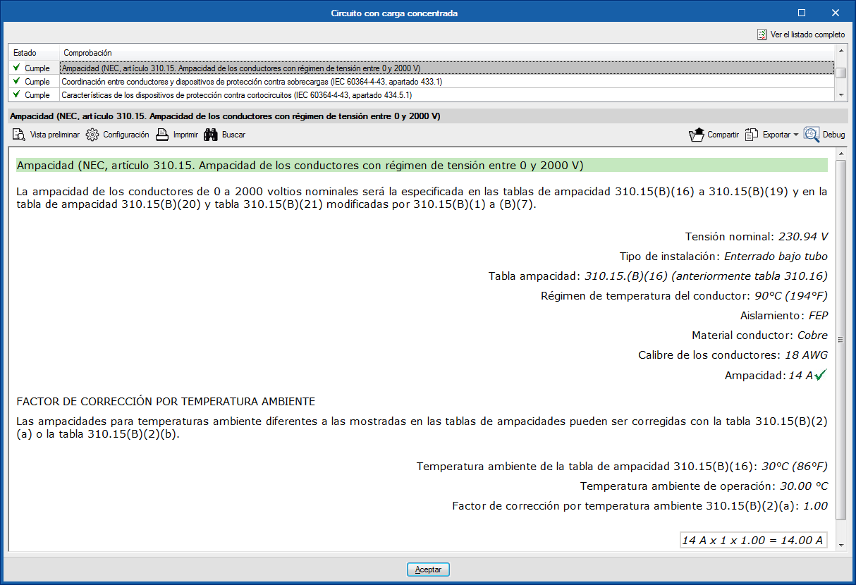
The checks are also adapted to the AWG cable selection. For example, the maximum allowable current check is substituted by the amapacity check of the cable according to the American standard (Natinal Electrical Code).
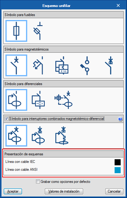
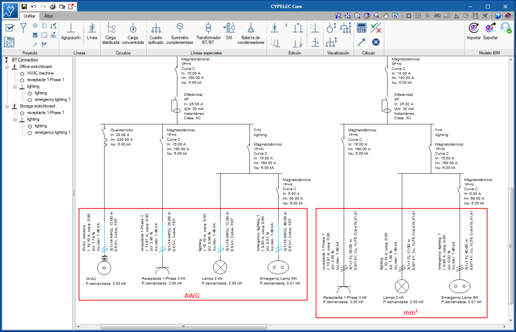
Since, as of this version, users can work on the electrical installation with cables in mm2 or AWG, in order to distinguish lines with IEC or AWG cables, they are drawn in different colours. These colours can be changed in the “Diagram presentation” section of the “Circuit diagram” dialogue box (“Circuit diagram” button of the “Project” section of the toolbar).
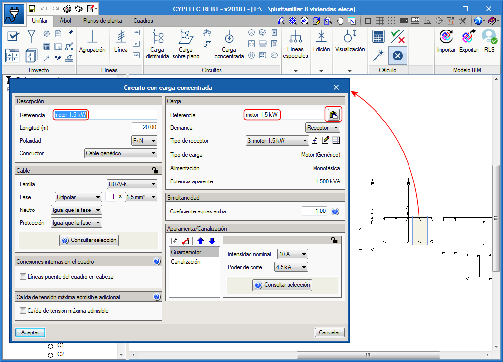
In some panels, as is the panels of circuits with concentrated loads, users can indicate a reference for the circuit and a different reference for the load. When the same reference is to be used for the circuit and the load, a button has been added (next to the reference of the load) to be able to quickly copy the reference.